Effective Reliability, Availability, Maintainability (RAM) and Safety (S), Principles and Guidelines for Large Subsurface Metro and Main Line Projects
Document
type: Technical Paper
Author:
Jonathan King FIET, Olga Gugala, ICE Publishing
Publication
Date: 09/07/2018
-
Read the full document
1 Reliability Availability and Maintainability
1.1 Early Life Cycle RAM and RAM Strategy
RAM requirements in large railway projects (such as Crossrail) are formed from a long time frame and a considerable suite of complex information. Projects investigate a variety of information which can include benchmarking other projects and operator’s systems performance. This includes risk evaluation and acceptance.
RAM begins by following guidance in BS EN 50126 [1] and its lifecycle related tasks. The complete life cycle can be seen in the Figure 1 which highlights the 5 early stages of RAM development. The first 5 tasks are usually with the DO to undertake with support from RAM engineers or specialist consultants. This is to develop and establish RAM requirements for design and implementation at stage 6.
Early stages are a critical stage of development and hard to achieve high accuracy. The BS EN 50126 [1] provides detailed guidance on phase related tasks that need to be undertaken. It is recognised at each of the early phases information required grows exponentially and sufficient resource needs to be provided to the project. Categories of information in [1] are expected to be undertaken and provided at each phase. This starts with each phase objectives, and its inputs. Leading onto the requirements and what needs to be finally verified on each phase.
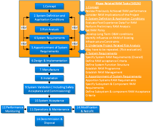
Figure 1 – RAM Life Cycle and Phase Related Tasks
By using these categories and undertaking the content in [1] RAM can be undertaken logically through the project life cycle. An example of content type required at the first stage i.e. concept, is shown below [1];
Objectives – understanding of system to enable all RAM other lifecycle tasks to be performed.
Inputs – scope and purpose of the project.
Requirements – environment, previous RAM requirements, RAM performance of similar systems,
Deliverables – structure adequate to implement RAM requirements of phases 2, 3 and 4.
Verification – adequacy of information developed and systems environment for this stage.
It can be seen from figure 1 the life cycle stages from one to 5 have a large degree of variance in activity, deliverables, and complexity. This paper endeavours to cover how Crossrail provided some of the above which were mainly in RAM plans, RAM apportionment and RAM target reports and through performance modelling.
1.2 Performance Modelling and RAM Development
Crossrail followed the same performance modelling as network rail (NR) projects. This is based on a suite of models of which the key ones are RailSys and transport reliability availability infrastructure logistics (TRAIL) software. RailSys is used to develop the timetable and is fed into the TRAIL model with data on the configuration of the railway. TRAIL runs the timetable repeatedly subjecting it to random delays based on input data. This delivers day-to-day public performance measure (PPM) and an average PPM over a year. The TRAIL model process can be seen in figure 2;
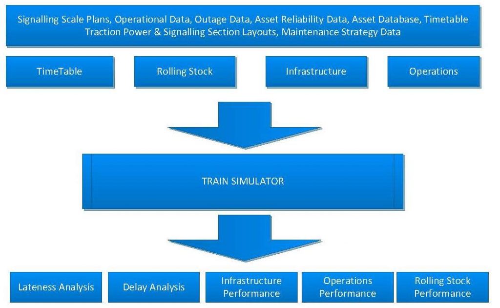
Figure 2 – TRAIL Model
Although this paper does not explain TRAIL in detail or it’s modelling it is recognised as an interface with RAM and therefore mentioned in this context.
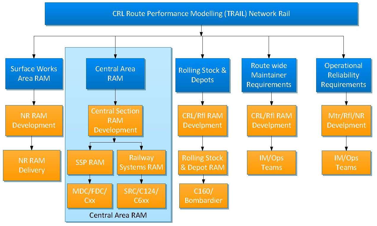
How TRAIL is provided across the programme is shown in figure 3. This illustrates TRAIL input/output data information for the surface works areas, main central area infrastructure and Systems (highlighted as focus of this paper), rolling stock and depots, and maintainer and operational requirements. The surface area works are undertaken by NR, where the central area and its infrastructure are delivered by Crossrail and its supply chain. The rolling stock and depots are provided and undertaken by Crossrail/Rail for London (rfl) and the supply chain.
The TRAIL model uses RAM target values from Systems which affect PPM. PPM at Crossrail is 95% provided at concept stage. The project determines which systems can affect PPM and are input with the RAM target i.e. the mean time before failure (MTBF), and mean time to repair (MTTR) to the model. These systems tend to be railway systems such as signalling, tunnel ventilation, and power.

Figure 3 – TRAIL and RAM on Crossrail
When TRAIL modelling is concluded targets are set in commercial contracts i.e. tunnel ventilation 99.95%. Each supplier complies with this target by undertaking RAM Engineering to BS 50126 [1], RAM plans, and prediction techniques to demonstrate targets are met. TRAIL is an iterative process and at some point the model is frozen and used as a base case. From thereon in configuration changes are costly and difficult. Figure 4 presents an overview of the Crossrail RAM development. RAM targets are developed alongside TRAIL. Crossrail opted to construct and formulate targets for Railway and SSP Systems differently. These are discussed in the following two sections.
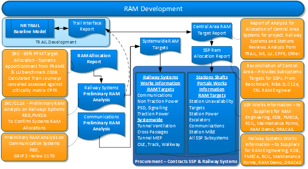
Figure 4 – Crossrail RAM development
1.3 Railway Systems Targets
For railway systems, target development started by using 95% PPM and utilising FRAME and London Underground (LU) data for systems and operational delays. To derive the service unavailability 100%-95% = 5% attributed to all delays. All subsystems and operations (A0 to AN) and operations summate to complete the subsystem apportionment which contribute to the service unavailability, and can be seen below;
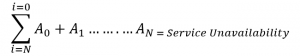
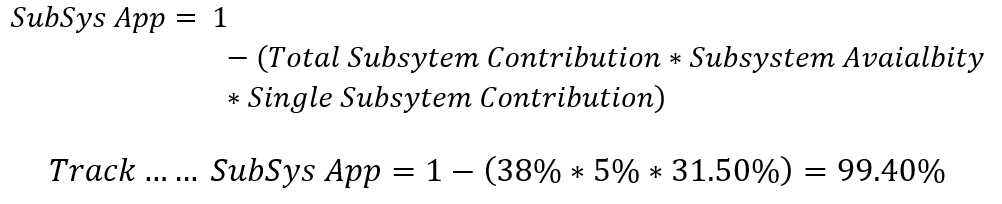
Additionally included in the service unavailability is operational delay at 62%. Therefore to allow for operational delay 38% is left for all subsystems delay contribution (i.e. 100%-62%). Each system can be apportioned from this in a percentage. Each of the subsystems apportionment (SubSys App) is then calculated. See below for each railway subsystem, and track is included as an example;

Each single subsystem contribution (i.e. 31.50%) is based on Frame/LU data. This can be seen in table 1.
Table 1 – Railway Systems Apportionment

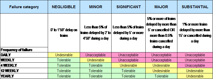
Preliminary RAM analysis is then undertaken to confirm the above values. The subsys app values can be taken forward to calculate effect on delay minutes/journeys. This depends on the project railway characteristics and business failure. This is different for each railway and also how the calculated apportionment (as above) is analysed against its business failure.
Crossrail typically used table 2 for requirements in this context, early in the project lifecycle.
Table 2 – Requirements
Communications preliminary RAM analysis’s was undertaken and also input to the systemwide RAM targets report. The central area target report brought in many other reports and analysis but essentially fed down into the SSP report which is mainly based on the following section details.
1.4 Station Targets and Unavailability Planning
The concept of service affecting failure at stations is less straight forward than railway systems. The effects are to passengers and station targets. These can impact on passengers and station accessibility which encompass a wider range of issues than equipment failures. Station RAM requirements can be reviewed from the following categories.
- Station safety requirements – Life safety systems such as emergency lighting, communications, smoke extract.
- Station performance targets – Broken down into part and full station closures (This can be seen in Table 3 derived from early workshops).
- Station Benchmarking – Obtain system targets from other projects or benchmark.
- Station Journey Times – Street to platform journey times can be measured and systems such as escalators can have impacts.
Station performance targets were generated from internal workshops and can be seen in Table 3 below; (excluding closures related to major /renewals).
Table 3 – Station Performance Targets
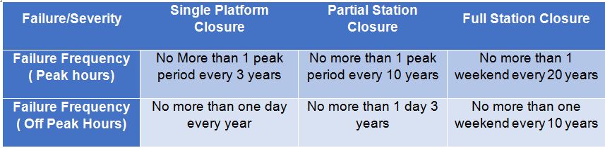
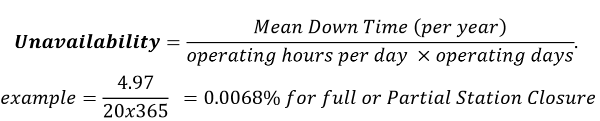
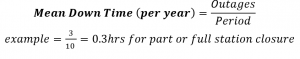
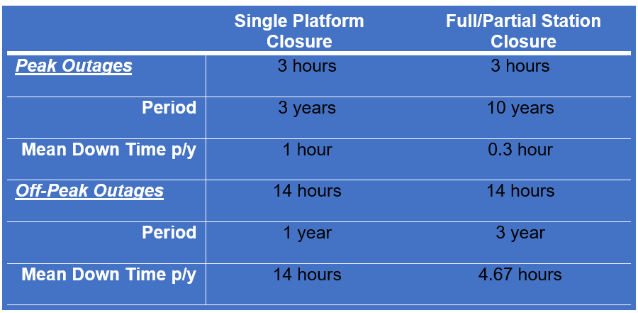
Using failure frequency on full/part and platform closure it can be then used to calculate the Mean Down time (MDT) per year shown in table 4, using the following calculation and assumptions;
Assumptions;
20 Operating Hours per day,
365 Operating days,
6 Weekdays – Peak hrs 7-10am, 4-7pm,
14 hours during week days off peak hours.
Table 4 – Table Peak and Off Peak Outages
MDT is can be summated from peak and off peak for a total. Then by using the following calculations with the same previous assumptions, table 5 can be provided;
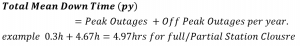

Table 5 – Station Availability Targets Summary

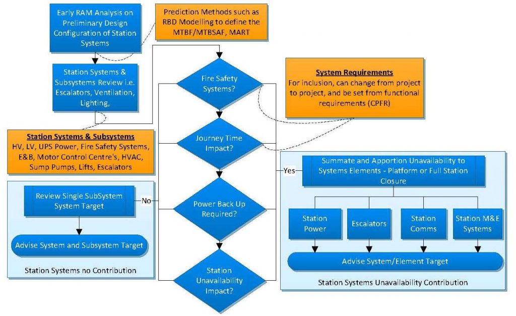
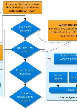
Figure 5 – Station Systems Review Method
From the station unavailability the station apportionment on subsystems can now be developed. The subsystems can be provided into the element groups as below (can expanded to suit project needs);
- Station high voltage (HV) power,
- Station escalators,
- Station communications, and
- Station M&E.
Each element is built up from the reviewing all station subsystems. When summated they make up the station unavailability. The complete process is shown in figure 5. Each subsystem is analysed for its MTBF and MTTR and if no RAM analysis has been undertaken then figures can be taken from similar systems in a similar environment. Following the process in figure 5 each subsystem shall be reviewed in terms of system impact, system type, or system effect on the station. If Yes – slot into a main element apportioned for platform or full station closure. If No – consider on a single subsystem apportionment basis.
Table 6 – Station RAM Target Unavailability
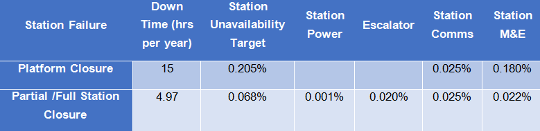
The procedure is based on experience of RAM engineers with input from RAM specialists or RAM consultants. For each element the station unavailability target is shown in Table 6. (Station power & escalators are not shown platform closure as they are not considered as a failure of a single platform).
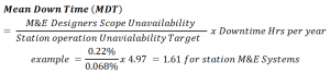
Each element in MDT hours per year can be derived simply by using the following; (M&E as an example);
1.5 Typical Project RAM Delivery and Alternative methods
RAM strategy plans delivery of RAM work from the DO through to the suppliers (SP). Provision of RAM engineering documentation from suppliers follows the BS EN 50126[1]. This guides projects for overall deliverables, management, and process. A typical RAM plan will provide the tasks and owner of each task and deliverable, respectively. Table 7 provides an example of this;
Table 7 – Typical RAM Delivery
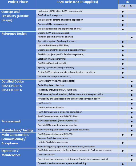
Figure 6 –
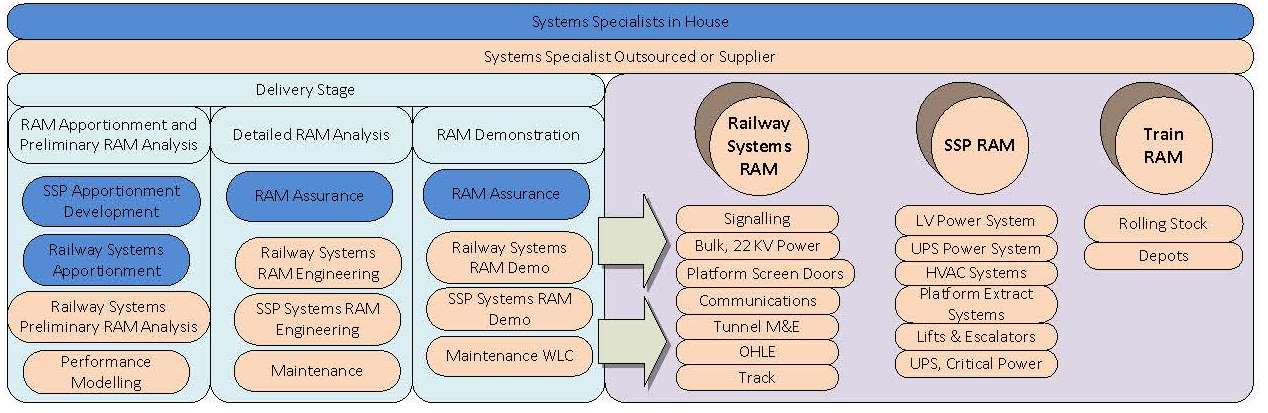
Traditionally on projects a considerable amount of RAM work is outsourced. For initial RAM development in concept stages it is advantageous to be undertaken by RAM specialists (in house preferred), or consultants. Whichever the case undertaking early life cycle high quality RAM is essential for a successful and worthwhile RAM delivery. Suppliers in a typical railway project deliver the vast majority of the RAM engineering from the scheme to final design, demonstration, and handover. This is for railway and SSP Systems. The typical RAM delivery can be seen in figure 7.
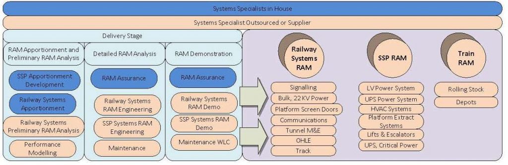
Figure 7 – Typical RAM Delivery
RAM constitutes a substantial amount of work and financial outlay (more so at the later stages). Sometimes the cost benefit of RAM is questioned. Therefore efficient ways to deliver RAM could be explored in mega railway projects. RAM is also not used to its full potential and tends to be recycled from project to project and more so used as an assurance tool, especially on some systems in railways.
System configuration can be set by standards before any RAM analysis is provided. Systems are often duplicated i.e. at the SSP. A single source RAM (or house) can be undertaken to reduce complexity and cost and also supply chains yield uncommon documentation and analysis. This can take up precious time and resource coordinating and assuring. The same strategy can be adopted for some railway systems. These are the systems which are unlikely to change from early concept design and where RAM data is readily available. A proposal can be seen in Figure 8 below;
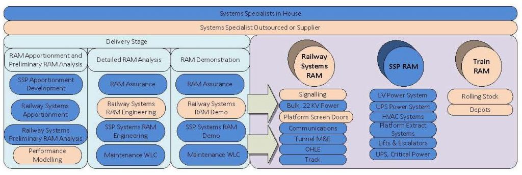
Figure 8 – Lean and Efficient RAM Delivery
The above can represent a more economical approach to RAM delivery with taking low risk. RAM costs are also exacerbated by the quantity of layers of suppliers, all taking an additional slice to the actual RAM baseline cost.
Other benefits providing this type of strategy is that the DO and the Infrastructure Manager (IM) can integrate information easier i.e. such as maintenance, whole life costs, and commonality. Crossrail can monitor system configuration changes due to RAM from concept design thorough to manufacture, testing, and commissioning for future projects. This would be the evidence needed (Currently no change exists due to RAM).
An exception to this strategy would be very specialist areas where novel or latest technologies are provided such as platform screen doors (PSD), signalling, and rolling stock. These systems are vulnerable to changes and their information tends to be sensitive due to intellectual property rights and therefore best kept outsourced.
2 Safety
2.1 Early Life Cycle and Strategy
The project safety strategy can be with suppliers to deliver the bulk of engineering safety management (ESM) with, assurance, integration and high risk analysis by the DO. ESM is directly linked to requirements that are mandatory from railway regulators, such as Office of Railway Regulation (ORR) and Railway Standards and Safety Board (RSSB). Safety is also linked with European and national safety targets recognised and monitored by the Department for Transport (DfT) and RSSB members. ESM also follows the BS EN 50126 and the yellow book, however in recent times the common safety method (CSM) replaces this for hazard compliance.
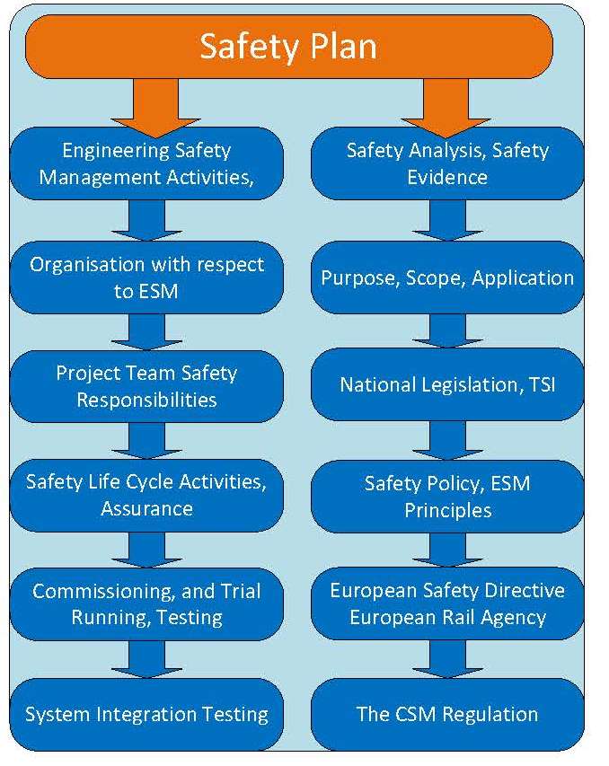
Safety activities that are carried out during the various stages of the project follow the general guidance of BS EN 50126, 50128, 50129. It is a requirement of any project that a project lifecycle is used for the development and application of appropriate safety activities at the correct part of the life cycle. The Safety strategy is deployed in the DO Safety plan. The plan sets out (see Figure 9) the overall strategy and approach mandated by the DO for the identification, control and management of system safety risks in the design, testing and potential future operation of the railway to as low as reasonably practicable (ALARP) in compliance with legal requirements. It also defines ESM arrangements and responsibilities for their delivery and covers the strategy for how the DO will deliver into Service. The safety of any integrated system comes from a combination of the engineering, operations, and maintenance arrangements. The DO delivers engineering safety cases which integrate into an overall operations safety case for a project.
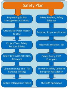
Figure 9 – Safety Plan Content
2.2 Project Wide Hazard Record and Hazards
A project wide hazard record (PWHR) is used as the main tool for hazard management system at Crossrail. The PWHR comprise hazards across the programme and is undertaken in comply-pro [2]. A hazard recording system can be provided in a schedule such as Excel or similar, which was used at the start of the project but this has much limitation. Projects should realise that the hazard management system is likely to be updated through the project lifecycle, especially long projects as better methods and techniques are normally found during project development. The Crossrail PWHR allows tracking and management of the hazards through the assurance process to closure, interface between contracts, and or, transfer to the railway operator. Limited access to the PWHR by contracts is allowed with training so each supplier can use the PWHR as their own hazard log. Crossrail can see in real time the hazard logs program wide in comply pro [2], see figure 10, which helps for overall management of hazards in real time if kept up to date.
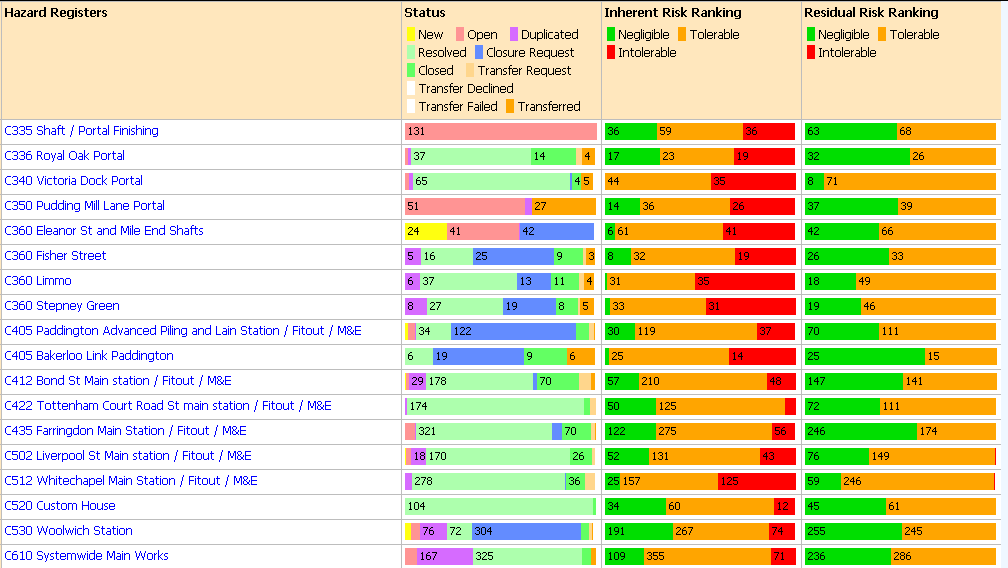
Figure 10 – Supervisory Management Features of the PWHR (in Comply-pro)
The design of a hazard management system should detail hazards to meet project and mandatory requirements be functional and user friendly. The hazard management system can become immense in size so it is critical that hazards are updated and closed during the life cycle. Managing hazards takes considerable time, effort, and resource. The main features of hazard management should include the following;
Unique ID, Generic Hazard codes,
Main Discipline, System and Subsystem,
Control Measures, Actions, Requirements, Evidence,
Risk ranking, Residual risk,
RO actions, transferred, closed, and
Hazard Owner, Hazard Assurance by DO.
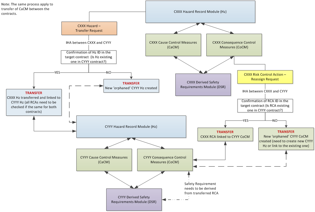
Hazard identification takes place during HaZid and HaZop workshops and during design reviews with CDM risks taken forward. Hazards identified by interface hazard analysis (IHA) or transferred from previous phase can also contribute. Figure 11 illustrates the process for transferring hazards between suppliers.
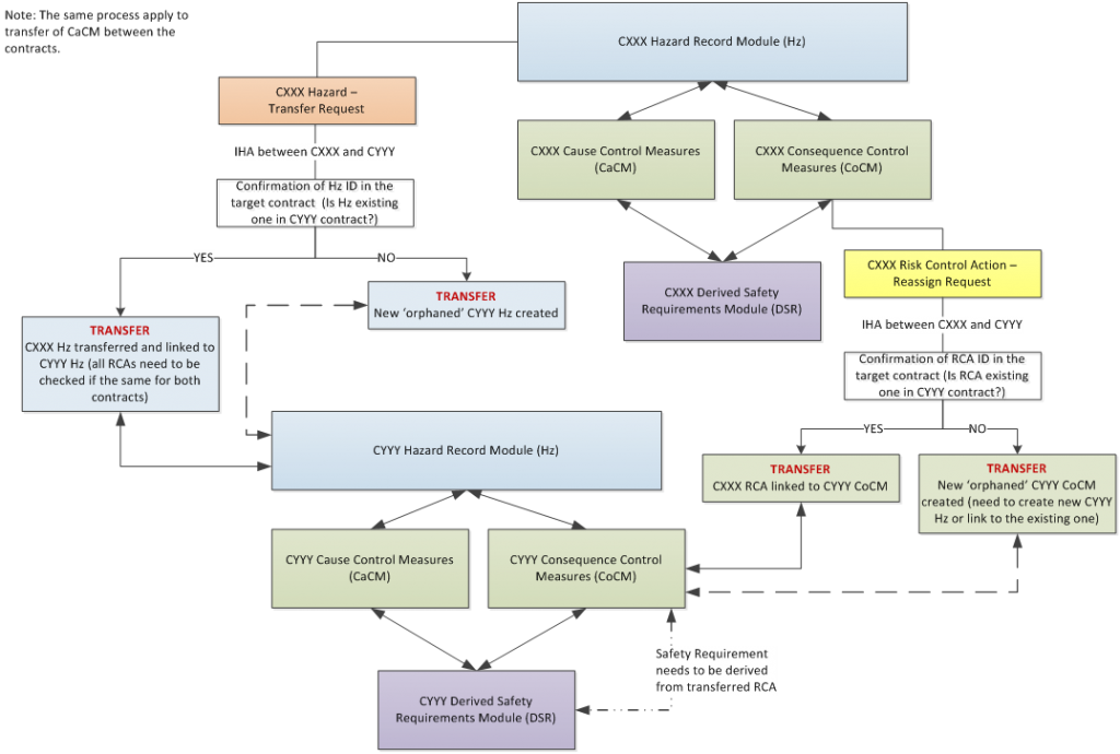
Figure 11 – Interface Analysis Process IHA (in Comply-pro)
During the IHA process suppliers could update fields in the PWHR regardless the status of the hazard or RCA. Each supplier prepared an IHA to confirm the engineering safety implications at internal and external interfaces were adequately addressed. The IHA involved relevant interfacing suppliers and third parties.
2.3 Safety Requirements
Safety requirements can be formed utilising a safety requirements specification (SRS). This SRS is traditionally undertaken early in the Life cycle from information such as standards, hazards, functional requirements, legalisation, operators, Rail regulators etc. They can be tracked through the life cycle via a standard requirements validation and verification (V&V) process. The SRS can be updated during future hazard management activities to capture new hazards during the life project life cycle.
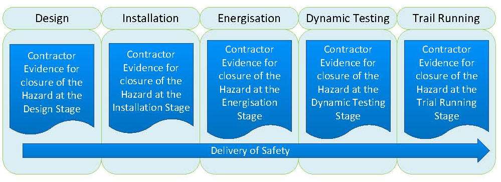
Figure 12 – DSR Module (in Comply-pro)
An alternative way to V&V hazards is in the PWHR. Such a system is implemented on Crossrail by using a derived safety requirements (DSR) module in comply-pro. The DSR runs parallel with the SRS for railway systems. For SSP the requirements are tracked through the DSR i.e. any previous SRS is ended. The module is implemented across the programme. The module allows suppliers to provide evidence through to trial running, and shown in Figure 12. To develop the DSRs the following needs to be provided;
Identify Safety requirement based on risk control action,
Give compliance rationale (partially compliant, non-complaint, compliant,), and
Generate evidence at applicable design, installation, energisation, dynamic testing and trial running stages of the project.
2.4 Safety Modelling and Strategic Engineering Safety Justifications (SESJ)
Safety considerations can be provided at central level. This is where there are known safety risks. Safety modelling and strategic engineering safety justifications (SESJ) can be undertaken. For safety modelling these are;
Derailment, collision, train held in section,
Train and station fire, and
Flooding.
They are modelled using mathematic analysis such as event tree analysis (ETA), fault tree analysis (FTA), and quantitative risk analysis (QRA).
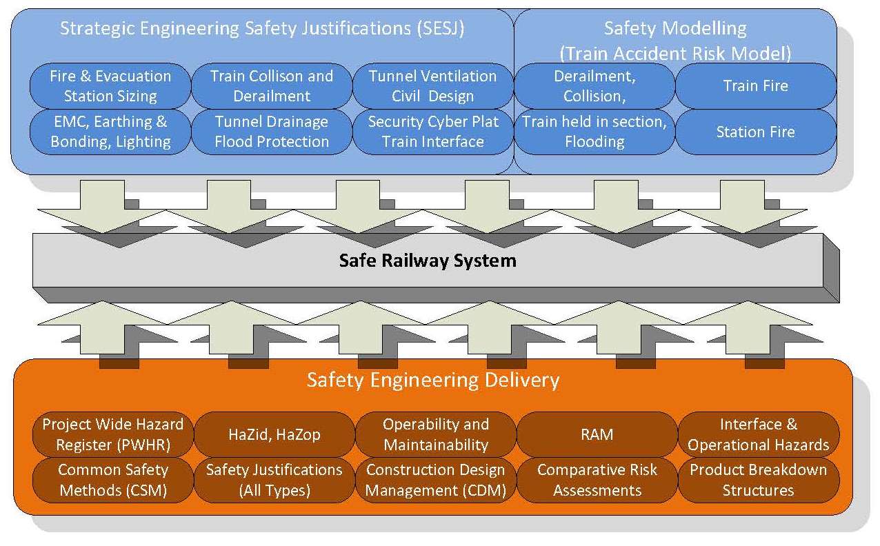
For SESJ it is a submission to rail assurance board Crossrail (RAB-C) as part of assurance process. These are studies provided for top level hazards generated from the Crossrail railway level hazard structure formed from the Crossrail generic hazard list, RSSB hazardous event description and LU network risk profile. The SESJ articulate how they have satisfied the safety requirements through safety justifications. The safety requirements are mainly via the operations concept and technical standards for interoperability (TSI). These will ultimately enable the IM to accept that the combination and integration of each SESJ in conjunction with the IM safety management systems provide a safe railway. This approach has been taken with safety modelling and SESJ (Top down), and standard safety engineering delivery (bottom up) to deliver a safe railway system, see figure 12.
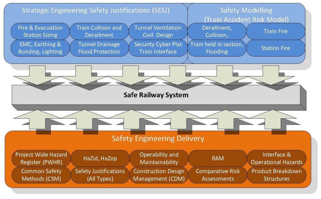
Figure 12 – Safety Approach on Crossrail
2.4 RAM and Safety Guidelines
Guidelines developed by the DO will benefit the project through the life cycle stages. The guidelines are critical, and should be developed at an early stage. Referring and following the guidelines of the BS 50126 is good and helpful for a project. However, project led information needs to be added due to the variety of methods, techniques and tools available, their interpretations and project compliance.
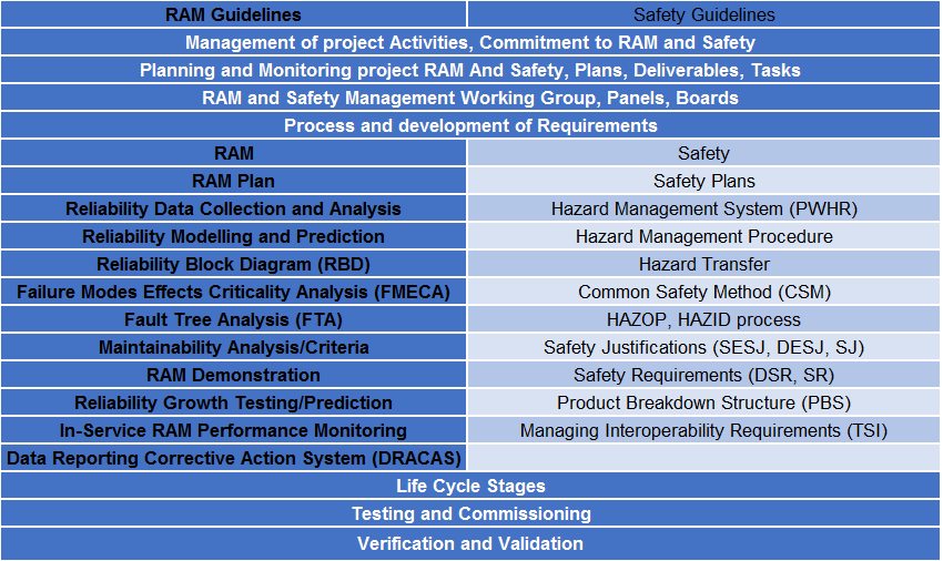
Guidelines are not just for suppliers but can be internally required for a project to comply with its safety requirements. Crossrail provided a safety manual which consisted of many such documents detailing the entire scheme of safety delivery i.e. end to end railway safety assurance. To achieve a high quality RAMS delivery the provision of guidelines is recommended for large projects with multiple suppliers. These are shown in table 8.
Table 8 RAM and Safety Guidelines
3 Summary
The initial RAM life cycle phases and tasks have been highlighted from BS 50126 and further explained on Crossrail due to their complexity and lack of information readily available. The paper offers some guidance on these features especially on apportionment development. A typical RAM plan and strategy is provided including an alternative RAM delivery strategy. This is to really think where efficiencies can be made without reduction in RAM assurance especially with supply chain.
The Safety plan features have been highlighted for a project. Specialist software tools are recommended for the PWHR due to its superior control and management features. An alternative safety requirements management is presented as the DSR method. This can also be tracked in the PWHR for V&V purposes. A Top down SESJ and safety modelling methods with the normal safety engineering delivery can be utilised on projects to establish the ultimate goal of delivering a safe railway system. RAMS guideline topics are provided for projects to enable the project and its suppliers, a compliant and quality delivery.
4 References
[1] British Standards “BS EN 50126– Railway Applications –Specification and demonstration of Reliability, Availability, Maintainability and Safety (RAMS)”, (1999 Part 1).
-
Authors

Jonathan King FIET - Crossrail Ltd
Jonathan has been working on the Crossrail project from 2006, firstly as a Crossrail supplier MDC, and FDC and more recently for Crossrail as an Engineering Manager and Engineering Safety Manager. Jonathan’s responsibility has mainly covered systems design, delivery, construction, and safety engineering aspects.
Jonathan has been in the Railway Industry for nearly two decades, working on projects such as CTRL section 2, Thames Link and SSL 4LM. Jonathan is also undertaking research on the Crossrail project under a programme affiliated with the University of Birmingham (UOB) for Reliability, Availability, and Safety (RAMS) and Integration.