Enhance the service reliability of safety critical mechanical installations
Document
type: Technical Paper
Author:
Wing Fung PhD MSc BSc(Eng) CEng MCIBSE, ICE Publishing
Publication
Date: 09/07/2018
-
Read the full document
Abbreviations
ALARP As Far As Reasonably Practicable ATS Auto Transfer Switch BMS Building Management System CMS Cable Management System CP Control Panel (PLC or hard wired relay logic system control panel) DALI Digital Addressable Lighting Interface DRACAS Data Reporting Analysis and Corrective Action System FAP Fire Alarm Panel FIU Fire Interface Unit LAN Local Area Network LED Light Emitting Diode LV Low Voltage MCC Motor Control Cubicle MEP Mechanical Electrical Public Heath OPE Overtrack Platform Extract PLC Programmable Logic Controller RAM Reliability Availability Maintainability RBD Reliability Block Diagram RCC Route Control Centre SCADA Supervisory control and data acquisition SOR Station Operating Room TVS Tunnel Ventilation System UPS Uninterruptable Power Supply VCS Ventilation Control System (for TVS) VSD Variable Speed Drive Introduction
Stair pressurisation, air release and platform smoke extraction are the three safety critical mechanical installations in Crossrail stations, shafts and portals. Basically, they are station ventilation systems that operate in response to a fire alarm signal or remote command. They share a common functional configuration (Figure 1). The key features of the system configuration are:
- Input command, normally a fire command from the fire control panel or external command from the central control room.
- Process control module that handles the system control logic and interlocking.
- Motor control including motor starters, safety control and cable configuration.
- Feedback control and remote condition monitoring.

Figure 1- Functional Configuration of a typical ventilation system
To meet the Crossrail reliability and availability performance targets, the following enhancements are made to the design:
- Two diverse sources of power supplies to the system.
- Duty and standby motor and motor control.
- Microprocessor based system control.
- SCADA/ BMS based remote condition monitoring.
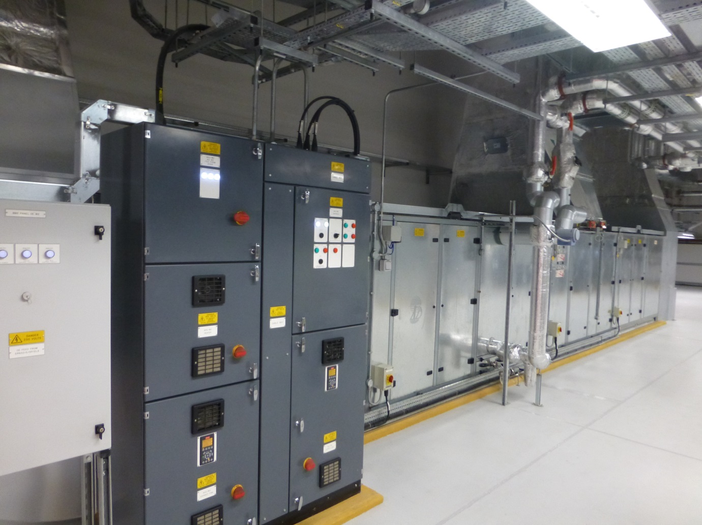
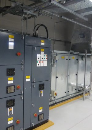
The preferred system configuration adopted is illustrated in Figure 2. A reliability block diagram (RBD) analysis was carried out at the design stage to demonstrate that the system will satisfy the reliability performance targets (mean time between failures, station/ platform closure etc.). Figure 3 shows a site photo of the process control and motor control panel in a fan room.
While the system configuration provides the backbone requirements on the design of the safety critical installation, there are specific details of the design that will influence the level of reliability and availability of the performing system. This paper examines some of these issues that have been addressed in the design review:
- The choice of process control technology for the assignment- building management system (BMS) vs Programmable Logic Controller (PLC).
- Centralized vs decentralized process control.
- Local networking configuration.
- Centralized vs decentralized motor control and BS EN code compliance.
- Testing regime to demonstrate reliability.
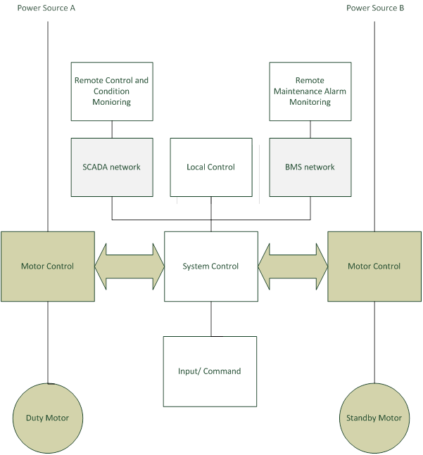
Figure 2- System Configuration of a typical safety critical mechanical installation

Figure 3- Site photo showing the system control panel (left) and motor control panel (centre)
Building management system (BMS) vs Programmable Logic Controller (PLC)
Microprocessor based process controller is an appropriate choice for the application because of the complexity of the process control logic for the safety critical installations in Crossrail. There are two major streams of process controller, namely PLC (programmable logic controller) and BMS (building management system). PLC is well established for production process control while BMS is well known for building system controls. Both are suitable for the purpose, having merits on controls and interactions with users. After a detailed study of the pros and cons of the two systems, PLC is considered more suitable to the needs of a safety critical installation. The following provides a summary of the considerations [1].
Table 1- PLC Vs BMS
Consideration User Requirement PLC BMS Key features Maintain the safety critical service in a secure and reliable manner Production process based. Primarily intended to control and protect the production process Object oriented. Primarily intended to control and protect the environment around People System Topology Single process control with interactions on remote commands and condition monitoring Usually limited to a single production line with limited connectivity to other worksites Control can range from a single to multiple worksites with active interactions among worksites Users’ interaction Minimal except for remote condition monitoring Only localized user interfaces although system allows interactions with SCADA and BMS for remote condition monitoring Configuration supports active interaction with users to optimise system operation Degree of determinism Deterministic system operation essential 1-50 ms scan time range. Highly deterministic system operation Report by exception. More adaptive as it gives communication functions a much higher priority Alarm detection and management Integration with BMS and SCADA system on operation and maintenance alarm management Limited connectivity. Transient alarms likely to be missed because of the communication overheads. Deficiency not a major issue as alarm management is taken care of by SCADA/ BMS. Alarms within BMS architecture are detected at the field controller level and processed as close to the signal source as possible. Excellent connectivity to remote monitoring and control stations Integration and interfacing Best remains as a standalone system other than essential interactions and interventions PLC interfaces are limited to a few complementary automation devices, involving custom coding and significant engineering hours Supports extensive, native integration capabilities and are often tied to numerous facility sub-systems. Able to integrate with Enterprise Business Applications Stability of operating system Stable and crash free Programming language and software structuring tools are written in low level language. Programming language and application software are written in high level language. Not uncommon with software bugs and system crashes. Centralized vs decentralized process control
Crossrail does not encourage the use of centralised process control for multiple installations. Examples of such cases are (i) a single PLC controls a number of stair pressurisation installations, (ii) a single PLC controls both the stair pressurisation, air release and platform smoke extraction installation. The use of centralized process controller will introduce an unwarranted single point failure mode that will have to be risked assessed and managed in the RAM process. It is highly desirable that all safety critical installations should function independently of each other and of other systems as far as practicable. In exceptional circumstances where a single PLC controls more than one installation, the following supporting assurance evidence will be required:
- All connecting control cables between the PLC, MCCs and system controllers are fire rated and tested to BS EN 50200[2]
- A system hazard study has been carried out to address system risks arising from the use of a central PLC.
- A RAM RBD analysis has been carried out on the centralized system control configuration and confirms that the configuration will not impair the overall station availability targets.
- A maintainability analysis has been carried out on the centralized system control configuration to confirm that maintenance and shut down of either one of the installations will not impair functioning of the remaining installations.
Figure 4 illustrates the preferred system control configuration for the pressurisation/ air release installation and platform smoke extraction installation. The preferred control configuration highlights the use of decentralized process controllers and a highly reliable interconnecting control network.
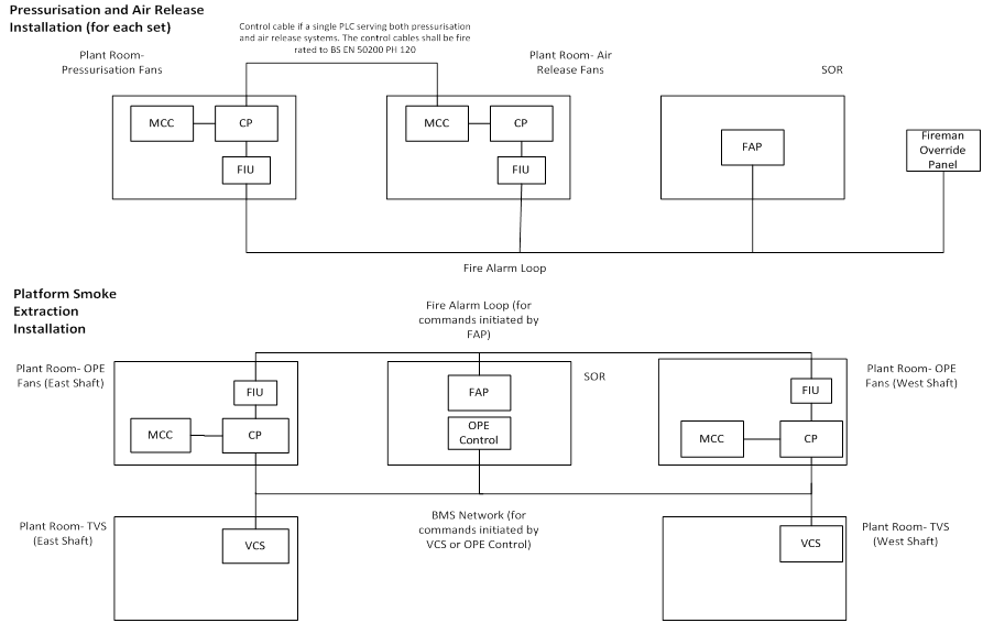
Figure 4- The preferred system control configuration for the pressurisation/ air release installation and platform smoke extraction installation
Local networking configuration
For Stair Pressurisation and Air Release Systems, The fire alarm loop provides a more secure and proven means of connection as compared with other bespoke networks. Therefore, the fire alarm loop should be used to provide interfaces with Fire Alarm Panel. In addition, the remote fireman override switch is considered a part of the fire safety system design and will be connected directly to the fire alarm loop via interface. Remote control of the system from the RCC is considered a part of the fire safety system design and will be connected directly to the fire alarm loop via interface. The remote control is applicable to shafts and portals only.
For Platform Smoke Extraction System, the fire alarm loop should be used to provide interfaces with the Fire Alarm Panel. The BMS backbone or other dedicated networks shall be used for the interface connections between the PLC and Remote control panel at SOR and Remote control from RCC. The fire alarm loop should not be used for this purpose as this remote control does not form part of the fire alarm system. Both BS 5839-1[3]and 4[4] recommend that ancillary equipment which takes power other than for indicating should not be connected directly to the fire system. Any control equipment which uses the fire alarm loop would need to be compliant with BS 5839-4 (specification for control and indicating equipment). It is most unlikely that the above remote control equipment is currently designed to this Standard. On the practical side, mechanical and fire systems maintainers would need to be on site simultaneously for routine testing of the interface network. This is not an arrangement that is acceptable to the future maintainer.
A safety critical installation should have a fire survival time of at least 120 minutes as far as practicable (for a fire occurring outside the plant room which houses the safety critical plant). To support this, control cables of the system outside the system plant room shall be fire rated and tested to BS EN 50200 PH120. This includes:
- Control cables to smoke control dampers in platform smoke extraction systems
- Control cables to pressure differential switches in stair pressurisation systems
- Control cables to smoke control dampers in the air release systems
- Control cables between the MCC and PLC if either one is situated outside the fan room.
BS 8519:2010 gives some detailed recommendations on cable installation practice to ensure that the circuit integrity of the installed cables is not compromised by other components of the system such as fixings, containment system, glands and joints.
PLC and control relay modules in the remote controllers shall be provided with battery back up supply for at least 120 minutes and status condition monitoring via BMS as they receive unsecure power supply from the local distribution panels.
Centralized vs decentralized motor control
A motor control assembly comprises of circuit breaker, power controller (starter, VSD, power relays etc.), motor control (control relays, interface circuits etc.) and associated wiring, CMS, control enclosures.
Crossrail recognizes that there numerous permutations in the configuration of motor control in consideration to the diversity of market available products ranging from proprietary integrated design to decentralized motor control assemblies. These variations will influence the overall reliability of the system and compliance to the Crossrail material and workmanship specification which was derived primarily on a basis of a centralized motor control scheme.
Figure 5 illustrates the preferred configuration of the motor control assemblies for the duty and standby equipment that is in line with BS EN 61439-2 Form 4a. Control of duty and standby motor is of a fail safe design such that failure of the integrated changeover logic and remote control/ monitoring module will not impair the operating status of the duty/ standby motors. It is desirable that adequate segregation be made between PLC/ relay logic module and the motor control modules. Crossrail requires that the motor control assemblies for MEP installations are constructed to BS EN 61439-2[5] Form 4a type 3. This construction segregates parallel systems enabling are to be maintained whilst the other remains operational without exposure to LIVE parts. There are cases in the construction design where motor control assemblies do not conform to this construction standard. Some of these cases are:
- Motor control assemblies that conform to Form 4a type 2 instead of type 3. In MCCs conforming to Form 4a type 3, the termination for each functional unit has its own integral glanding facility whereas for Form 4a type 2 cables may be glanded elsewhere. Crossrail has no objection to the use of Form 4a type 2 MCC on condition that the use of type 3 MCC was not specifically included in the Contractor’s RAM system design.
- Proprietary design where the motor control panels do not conform to BS EN 61439-2 Form 4a Type 3. Normally, these are panels used for small ventilation fans and circulating pumps.
- Decentralized panels with separate power and control enclosures. They are connected through cables encased in CMS. These enclosures may not conform to BS EN 61439-2 Form 4a type 3.
- An integrated motor control design for duty and standby motors. In these designs, inadequate segregation is maintained between duty and standby motor control circuits when they are installed in close proximity to each other in a plant room. Furthermore, failure of the integrated changeover logic/ remote control and monitoring module may disable both the duty and standby motors. This will create undesired single point failure modes and will adversely affect system reliability.
Where a decentralised motor control assembly with proprietary integrated motor starters or variable speed drives enclosed in their own integral housing are used, consideration will be given to the way in which the assembly is to be operated and maintained throughout its anticipated life span. All single point failure modes arising from the decentralised design should be reviewed in the RAM system analysis report and designed out in accordance with the ALARP principle. Configuration of the integrated duty/ standby motor control assemblies adopted in the design shall be accurately reflected in the RAM system analysis. All single point failure modes arising from the design should be reviewed in the RAM system analysis report and designed out in accordance with the ALARP principle.
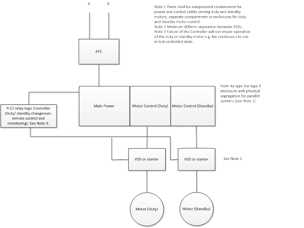
Figure 5- Preferred configuration of motor control assemblies for duty and standby equipment
In the review of proprietary designed motor control panels and power control panels that do not comply with Crossrail material and workmanship specification, consideration will be made on the size of the motor (e.g. motor control panel for toilet extract fan) and whether it is part of the integrated design for the equipment (e.g. in-built starter panel in a packaged air cooled chiller). There is an increasing tendency for integrated motor starters and variable speed drives to be enclosed in their own integral housing. This provides an opportunity to use the device’s integral housing as the means of separation or, alternatively enclose the complete device within a compartment within the assembly (compartmentalised) in a motor control cubicle. The use of the device’s integral housing as a means of separation does not necessarily conform to Form 4a type 2 or type 3. Whichever approach is used, the chosen devices and the assembly as a whole must meet the safety and performance criteria set out in the standard. Generally, use of the integral housing as a means of separation will lead to the most compact assembly, but its suitability will essentially be determined by the way in which the assembly is to be operated and maintained throughout its anticipated life.
The power controllers (including variable speed drive) for the duty and standby motors are housed in separate enclosures. Furthermore, the power control enclosures are spaced at least 600mm apart should they be of non-metallic construction (as might be the case for VSD). Incoming and outgoing power cables for the duty and standby motor control circuits shall be housed in separate cable containments. The motor control layout design should allow maintenance work (e.g. routine maintenance, fault finding, replacement of fuse links or adjustment of control settings) for either of the duty or standby motor control circuits without the need to shut down the whole duty/ standby system. Form 4 type 2 or type 3 MCC allows for this.
To maintain a consistent level of panel operability, the integrated motor control assemblies have been fitted with the following man machine interface provisions as a minimum:
- Phase healthy LED lamp for each incoming phase.
- Controls healthy LED lamp.
- Lamp test button or push to test lamps.
- Run and trip/ fault lamp for each item of equipment.
- Alarm LED lamp for each safety circuit.
- Hand/ Off/ Auto switch for each item of equipment.
Testing regime to demonstrate reliability
The failure rate for most MEP systems in Crossrail can be described in a ‘Bathtub Curve’. The failures exhibited in the first part of the curve, where failure rate is decreasing, are called early failures or infant mortality failures. Infant mortality is usually related to manufacture and quality assurance e.g. welds, joints, connections, dirt, impurities, cracks, insulation or coating flaws, incorrect adjustment or positioning. The middle portion is referred to as the useful life and it is assumed that failures exhibit a constant failure rate, that is to say, they occur at random. The latter part of the curve describes the wear out failures and it is assumed that failure rate increases as the wear out mechanisms accelerate.
The following reliability tests shall be carried out as a minimum on the MEP Installations to help reduce infant mortality as far as possible prior to system handover:
1. Run in tests for systems and specified assets
Operation and safety systems have to complete the specified minimum cumulative run time. Through the test most infant mortality issues should be identified and resolved. Furthermore, defects noted in the test will provide useful information to support the DRACAS and reliability growth study.
2. Failure free continuous test run
Test run for the specified time period for specified systems and assets. The test is needed to demonstrate that plant can deliver failure free service during revenue operation. Tests have to be re-run until failure free duration is achieved
3. Change over cycle tests
The tests are applicable to redundancy design (e.g. duty/ standby equipment, ATS, UPS changeover, LV A&B changeover).
4. Cycle Tests for equipment
The tests are applicable to equipment which contributes to single point failure mode (e.g. fire and smoke dampers).
The following Table provides specific details of the reliability tests:
Table 2- Specific requirements of the Reliability Tests
System/ Equipment Run in test (Cumulative hours) Failure free continuous run (Continuous hours) Change over cycle test (Number of cycles) Cycle Test (Number of cycles) Main LV Switchboard 1000 50 Platform Smoke Extraction System 150 10 Staircase Pressurisation and Air Release System 150 10 LV A&B changeover 5 Duty standby changeover for plant ≥ 5kW 5 Air Circuit Breaker 1000 5 ATS 1000 5 Fire and smoke dampers 5 Main air flow control dampers 5 The minimum cumulative run hours in Run-in Test (column 1 above) was determined based on MTBF of typical system configuration. This is the minimum cumulative run hours that the system/ equipment have to achieve on continual basis prior to system handover.
Conclusion and Lesson Learnt
The mechanical safety critical installations in Crossrail have to meet reliability and availability targets. While redundancies in power supply and motor drive have been built to the system configuration, there are specific areas of design and system tests that have to be addressed to enhance the overall reliability and availability of the system. This paper provides an overview of these issues and suggests ways to mitigate these issues.
The following lessons learnt can be drawn from works in the Crossrail:
- PLC offers a more suitable process control service for safety critical installations.
- Centralized process control for multiple safety critical installations should be avoided.
- More attention should be made on the local network configuration and its construction details.
- More attention to segregation of duty and standby control and power components.
- Development of an appropriate testing regime to verify system reliability is important.
References
[1] Why BMS not PLCs for Building Automation, TAC, www.tac.com, 2007
[2] BS EN 50200:2015, Method of test for resistance to fire of unprotected small cables for use in emergency circuits, BSI, 2015
[3] BS 5839-1:2002, Fire detection and fire alarm systems for buildings. Code of practice for system design, installation, commissioning and maintenance, BSI, 2008
[4] BS 5839-4:1988, Fire detection and alarm systems for buildings. Specification for control and indicating equipment, BSI, 1998
[5] BS EN 61439-2:2011, Low-voltage switchgear and control gear assemblies. Power switchgear and control gear assemblies, BSI, 2011
-
Authors

Wing Fung PhD MSc BSc(Eng) CEng MCIBSE - Arcadis
Technical Director (MEP), Arcadis
Wing is is a Chartered Engineer with over 30 years’ experience as a technical specialist engaged in mass transit system planning, design, project management, technical assurance, commissioning, energy management, operation and maintenance, and asset renewal. Wing has been with the Crossrail project in the CRL Chief Engineer Group since 2013, overseeing mechanical design, systems integration and T&C.
Specialties: Building Services, Mechanical Engineering, Computational Fluid Dynamics, RAM studies, Systems Integration, Requirement Management, Testing and Commissioning.