
Examples of Specialist Grouting on Contract C310 Thames Tunnels
Document
type: Technical Paper
Author:
Richard Smith
Publication
Date: 10/11/2015
-
Read the full document
Introduction
Keller has been employed by the Hochtief Murphy Joint Venture (HMJV) to undertake a combination of ground treatment and settlement mitigation measures on the Crossrail C310 Contract. The works have been completed to a very high standard and due to a good collaborative working relationship which has developed between HMJV and Keller, a number of additional design and construct works packages have been completed by HMJV and Keller.
Cathedral Substation Compensation Grouting Scheme (Value £2.0million)
A Network Rail substation which provides the power supply to the North Kent Line – a busy commuter route into London, lay directly above the line of the proposed Crossrail tunnels. The substation is within 100m of the launch of the Tunnel Boring Machine (TBM). As shown in the section drawing below the TBM was still at a shallow depth when it advanced past the Cathedral Substation (less than 5.0m between the crown of the tunnel and the base of the building’s footings). Based on this, a settlement calculation completed by HMJV calculated that during tunnelling a maximum settlement of 20mm was predicted.
The building housed a number of sensitive power supply equipment and therefore a settlement control criteria of +5/-10mm during tunnelling was stipulated.
The photo below shows the sub-station building. It is a Victorian built structure with a 300mm thick floor slab with structural edge thickenings to support the main structure of the building.
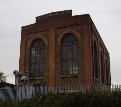
Photo 1 – External View of Cathedral Substation
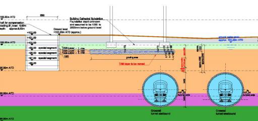
Fig 1 – Cross Section showing depth of TBM below the Cathedral Substation footings. Approximately 5.0m space between the base of the footing and the crown of the tunnel.
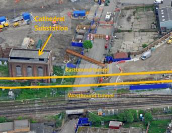
Photo 2 – showing the Cathedral Substation position in relation to Launch Portal for the Tunnel Boring Machine
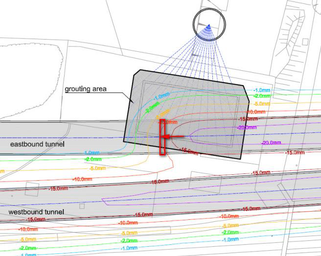
Fig 2 Layout Drawing showing settlement predictions during TBM Passage passed Cathedral Substation
HMJV were employed by Crossrail to develop a settlement mitigation measure, to control the settlement during the TBM drive to the stipulated levels. Through early sub-contractor involvement with Keller, a compensation grouting scheme was developed. Compensation grouting is a relative new and innovative geotechnical technique, first used in the UK on the Jubilee Extension Line. (Mair 1998)
Compensation Grouting is a three phase drilling and grouting process which uses a surveying system installed around the building to accurately record movement in real time.
The photo below shows the Hydrostatic Levelling Cells (HLC) which were installed around the Cathedral Substation. The information from these cells was transferred via an internet connection to a database and this information was shown on a drawing using the Grout Control Software. Below is screen shot showing the HLC results in real time.
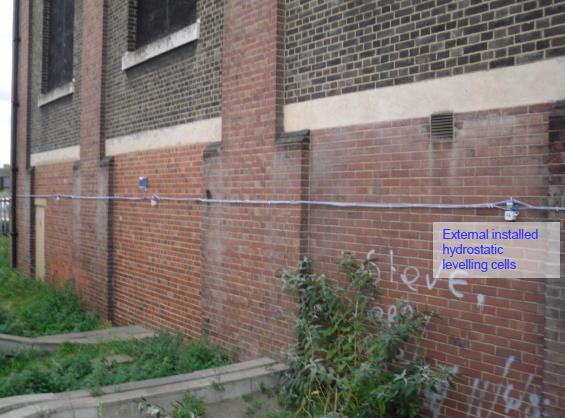
Photo 3 – showing the HLC installed around the outside of the Cathedral Substation. Monitoring system was installed by Keller Getec.
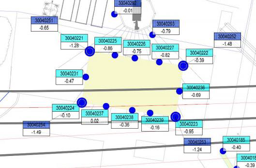
Fig 3 Grout Control Screen Shot– HLC recording being shown
The first phase of the compensation grouting scheme is the installation of a horizontal array of Tube a Manchette (TaM) pipes. An access shaft is required to allow access for the rig to install the TaM pipes. Using a specially modified restricted access drilling rig, temporary casing was installed to the required depth. TaM pipes in 2.0m lengths are installed to the required length and connected using a thread connection. Please see photograph below which shows the ‘shaft rig’ installing the temporary casing required to install the TaM pipes.
A modified Klemm Rig was used for the shaft rig with a duplex drilling head. This allowed the advancement of both the augers and casings as required. The drilling system used were drilling rods with drag bit using a water flush. The casing diameter was 114mm OD.

Photo 4 – Shaft Rig installing TaM pipes
Construction Risk Overcome
Due to the shallow depth between the TBM and the foundation of the building, the space available for the compensation scheme was less than 5.0m and one of the key risks which needed to be controlled was the potential of grout ingress into the TBM face during concurrent Grouting. .
This risk was managed by using a three array layout for the scheme as shown in the section drawing below. The top and bottom array acted as a protective grout slab when concurrent grouting was being completed as the TBM advanced. In addition using a traffic light system, a detailed drawing was produced which showed which TaM pipes could be used as the TBM progressed beneath the building. This system was successfully implemented during the works.

Fig 4 – Section drawing showing the three levels of TaM installed in relation to the TBM drive and the Substation footings.
The drilling works were completed from within a shaft, approximately 5.0m below ground water level – which equated to 0.5Bar of back pressure. When drilling works were being completed, there was an increased risk of settlement fine loss into the shaft. To overcome this risk, a Stuffing Box was used to drill through, this controlled the water ingress into the shaft. To actually install the TaM to the required length proved difficult, as they were being pushed passed a 0.5Bar backed pressure and therefore a flushing mechanism for the TaM pipes was developed which allowed the TaM pipes to be pushed to full depth.
The second phase is a pre-treatment phase. Using the TaM pipes grout is injected using controlled pressures and to a set system. An innovative approach used on this scheme was the combination of the pre-treatment phase with the drilling. This allowed far better control of settlement induced during the drilling works This meant that grout was injected in a controlled fashion as soon as TaM pipes were installed ensuring no significant settlement was observed during the drilling phase.
A software system called Grout Control was successfully used on this project. The software allows grouting to be implemented in real time to allow quick reaction to settlements observed. Provided overleaf is a typical drawing provided by the software. The drawing shows a proposed grout pass shown in green based on the settlement recorded by the HLC installed on the building.
Using a Maxibor surveying tool, 3D Modelling of the as-built position of the TaMs was complete to ensure none were in the line of the TBM. This also allowed the 3D model to be incorporated into the BIM model for the scheme.
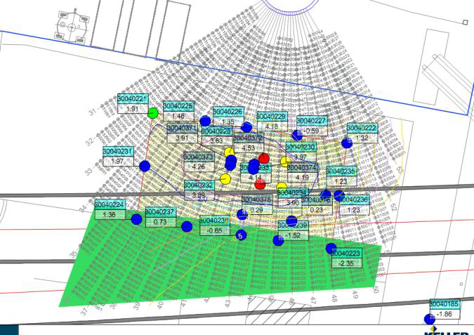
Fig 5 – Drawing produced by grout control software showing the position of the proposed grout pass.
The works were completed to a very tight programme working 24/7, the pre-treatment had to be completed to the required contractual dates else the Tunnel Boring Machine would not have been permitted to commence. This was successfully achieved.
Concurrent Grouting
The graph shows the control available from the grouting system. As soon as a settlement trend was noted, a grouting pass was initiated which jacked the building back to level. The works were completed within the specified movement criteria of +5/-10mm and even better settlement control was achieved with no movement greater than +5mm/-5.0mm being recorded.

Fig 6 – Graph showing the movement of each of the HLC installed at the Cathedral Substation during the concurrent grouting phase as the TBM passed beneath the building
Cross Passage 19 Jet Grouting and Chalk Fissure Grouting
Value – £1.0million
Between the two Crossrail running tunnels, emergency cross passages are to be constructed by HMJV. The cross passage are located within the highly permeable chalk layer and therefore to allow the construction of the cross passages to be completed, the permeability of the chalk needed to be reduced to an acceptable level. At one of the cross passage locations, the Crown of the Cross Passage was very near the interface between the chalk and the Thanet Sand. Therefore a normal fissure grouting scheme would not have been able to treat the Thanet sands, therefore a combined jet grout and chalk fissure grouting solution was designed and implemented by Keller.
A 4.0m jet grouted slab was constructed between the interface between the Thanet sand and the weathered chalk layer. The slab extended the full length of the cross passage (approximately 20.m) and 3.0m beyond either side of the cross passage. Interlocking jet grout columns were installed to 1.75m diameter. The jet grout was installed between 12m and 16m below ground level.
To confirm the column diameters achievable in the ground conditions Keller completed a number of trial columns. To assess the diameter of the columns Keller used the innovative technique of temperature measurement. The temperature increase in the centre of the column is monitored and compared with the result of a thermos-chemical analysis of the hydration process in the column. (Meinard, Adam & Lackner). When back analyses of the grout mix of 1:1:0.01 CEM II/Bentonite was completed it demonstrated a column 1.75m in diameter was achievable.
To comply with the Crossrail specification, a Falling Head Tests and laboratory testing on cored samples were completed. These demonstrated the jet grout slab achieved a permeability of better than 1 x 10⁻⁸ms-1.This demonstrated the works were in compliance with specification.
To ensure a complete slab was provided at Cross Passage 19, Keller used a SAA surveying tool to provide the 3D model. The photo overleaf shows Keller’s Site Engineer installing the SAA through the jet grouting drilling equipment.
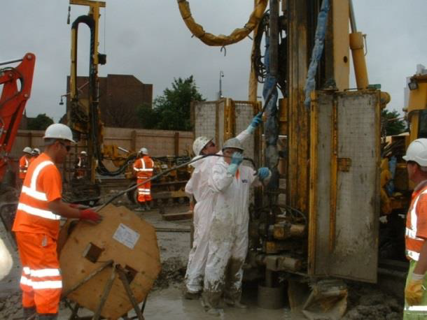
Photo 5 – SAA tool being installed into jet grouting drilling tools.
Using the results of the SAA survey, a 3D model of the completed column slab was completed. Using this model, an assessment of any gaps between the columns could be completed and if required additional columns were installed. Below is the 3D model completed at Cross Passage 19.
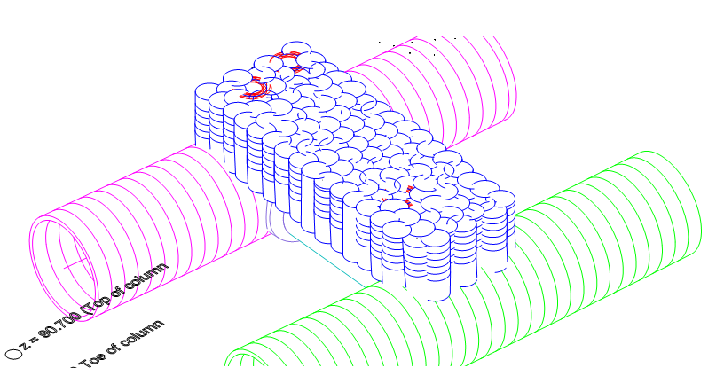
Fig 7 – Figure showing the completed 3D model of the jet grout columns installed at Cross Passage 19.
A secondary chalk fissure grouting was then implemented below the jet grout slab to a maximum depth of 25.0m. This was completed using a descending stage technique. Lugeon water testing was used to verify the woks complied with specification. 95% of tests were less than 2 Lugeons and 100% were less than 5 Lugeons. Photo 6 shows HMJV beginning the excavation of the Cross Passage.
The table below shows the grout take used at XP19 when compared to chalk fissure grouting on the CTRL cross passages: the table demonstrates that poorer quality chalk can be treated using a combination of jet grouting and chalk fissure grouting although the grout take is significantly higher.
Cross Passage TBM Face Geology Ground Treated (%) CTRL XP2 B5 7.7 CTRL XP3 and Nadir A2/A3 1.2 and 0.8 CTRL XP4 C3 4.4 Crossrail XP19 C4/5 – C2/3 9.0 Table 1 – Grout take used on chalk fissure schemes on CTRL and Crossrail schemes (Warren 2002).

Photo 6 – Exposed face at XP19.
3 Marmadon Road Reception Shaft
Value – £600k
Background to the Project – Keller were employed by HMJV to provide a design and construction of reception shaft for a pipe jack machine. The pipe jack was required to replace an existing sewer which clashed with the proposed tunnel portal structure.
Solution Provided – The position and access of the reception shaft was very constricted. The position was within a very small back garden of a terraced house which backed onto a railway line. Due to this, a secant wall shaft using a restricted access piling rig was proposed. The ground conditions showed a very high ground water level and due this a jet grout base slab was proposed by Keller. This was completed using a restricted access jet grout rig.
The secant wall was installed to using 508/450mm diameter hard pile and a 450mm soft pile. Both the hard and soft piles were installed to a depth of 7.0m. The excavation depth for the shaft was 5.0m. The jet grout slab was created using interlocking 1.75m diameter jet grout columns, varying in length 2.0m – 6.2m.
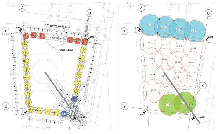
Fig 8 – Layout of the secant wall and the jet grout slab.
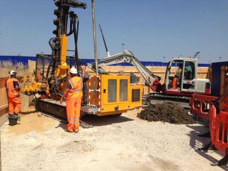
Photo 7 – Mini-piling installing 450mm diameter piles for the secant wall. Very limited space provided on site.
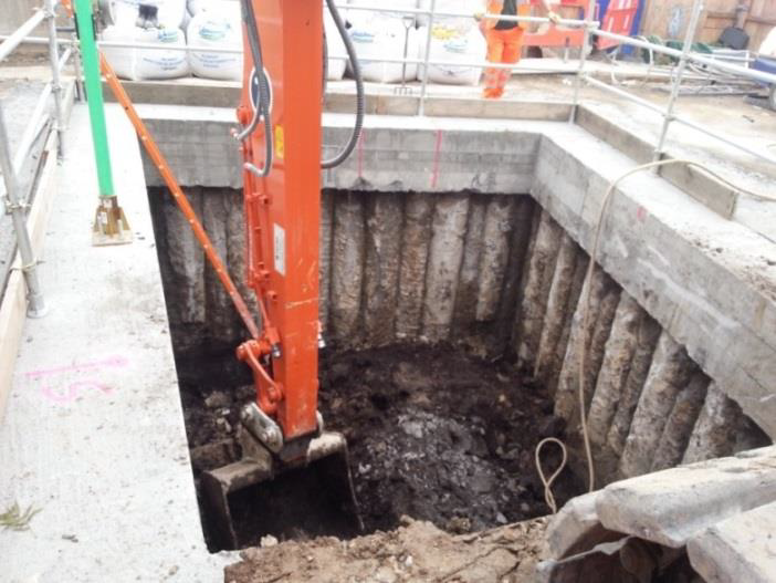
Photo 8 – Shaft being excavated during the works
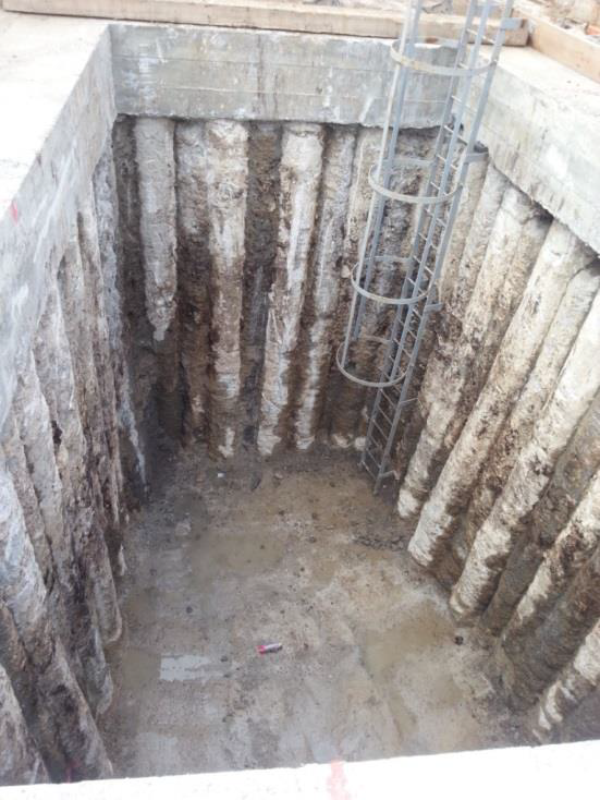
Photo 9 – Shaft excavated to top of the jet grout slab. The surface water shown is from heavy rainfall prior to taking this photo.
All this work was completed remotely from the main site as there was no space on the site except for the rig and an attending excavator. All concrete had to be delivered to the main site and then pumped beneath the railway line to be used on site. This required control of the concrete and grout mix used to minimise the risk of blockage.
This works is provided as another example of early subcontractor involvement within a scheme and therefore the risks of working in a confined site, close to a railway line were adequately controlled. All works have been completed and were completed within the required programme duration with no incidents recorded.
A key sustainability benefit completed from these works was that the spoil generated from the jet grout production was used to backfill the shafts used for the compensation grouting works.
References
Meinhard, Adam & Lackner Temperature Measurements to Determine the Diameter of Jet Grouted Columns
Warren, Hughes, Swift, Mielenz (2002) Cross Passages Ground Treatment for the CTRL Thames Tunnel
Mair (1998) Recent experiences of tunnelling and deep excavations in London
-
Authors