Farringdon Station SCL Design – Reducing risk at the heart of Crossrail
Document
type: Technical Paper
Author:
Andrew Davis, Phillip Duarte CEng MICE, ICE Publishing
Publication
Date: 03/11/2014
-
Read the full document
Tunnelling in Farringdon
Farringdon Station consists of approximately 1 km of tunnels to be constructed using a “Sprayed Concrete Lining” (SCL). The tunnel layout comprises a network of subterranean platform tunnels, connecting cross passages, concourse tunnels, escalator inclines and ventilation adits (see figure 1). The tunnel excavation diameters vary from approximately 6m to 11m and will be constructed at depths of up to 35m below ground surface beneath a congested area of central London that forms a major transport hub and employment centre for thousands of commuters. Impacts from tunnelling on these activities could be serious and potentially affect two London Underground lines, Thameslink services and Smithfield Market.
Farringdon station is situated in the middle of the central tunnelled section of the Crossrail alignment and is one of the final construction activities where the running tunnel TBM’s meet for dismantling. Logistically, this represents a challenge to ensure that the construction of this station meets key programme milestones and therefore not delay the completion of the network. In isolation, this is already a key constraint; however Farringdon station has many unique challenges not faced elsewhere on the project with the main differentiator being the expected ground conditions (Figures 2 and 3). This was fundamental to understanding how to manage the engineering risks to safely build the tunnels, risks which needed to be shared and understood by all involved in the design, including the Client.
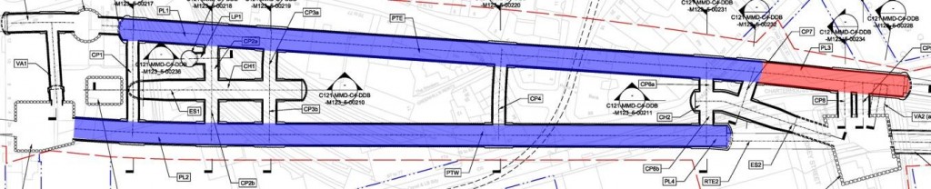
Figure 1 – Tunnels subject to further investigation
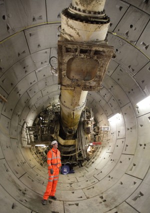
Sprayed Concrete Lining
SCL tunnel excavation is undertaken through spraying concrete directly onto the exposed excavated ground, forming an immediate and intimate bond with the strata. It interacts actively with the excavated ground surface instead of passively requiring the ground to move before it begins to resist that movement. In addition, the lining can easily follow complex profiles and layouts, in-fill over-break, and forms a strong, durable and watertight shell. As such it is an ideal method for the construction of complex station layouts. If required, initial ground stability can be enhanced through dewatering, the installation of canopy tubes and spiles, grouting, sub-division of the face and/or use of compressed air (thought the latter is fast becoming obsolete in the UK due to reduced working efficiency and H&S concerns).
Typically, in soft ground, excavation is carried out in different headings (for example a top heading, bench and invert) with SCL support applied as required. On the Crossrail project support is provided through an immediate SCL sealing layer of approx. 75mm (or thicker if a longer construction activity is anticipated – such as breaking out of a box) applied to any freshly excavated ground followed by a primary lining sprayed to the required design thickness. A waterproofing membrane is then applied (sheet or sprayed) with a final secondary lining, which can be sprayed or cast in situ. Depending on the size of the tunnel, a pilot tunnel may be required (a smaller tunnel within the larger tunnel) to facilitate excavation, control face stability and reduce risks. Due to the risks at Farringdon pilot
tunnels were widely adopted but the ones which caused the greatest concern, and the focus of this paper, were the large platform tunnels, representing approx. 650 m of tunnellingSCL is more dependent on the individuals carrying out the tunnelling and therefore has a greater reliance on human judgement than other tunnelling methods. For this reason, a substantial amount of work was carried out looking at ways to reduce this variable as well as provide a comparatively safer way of forming the pilot tunnels for the platform tunnels, in this highly variable stratum.

Figure 2 – Farringdon station Location and route geology
Geology
The geology at Farringdon Station is typical for that of east central London; comprising of a sequence of strata from Thanet Sand, the complex Lambeth Group strata and the lower A2 & A3 units of the London Clay. The only stratigraphical units that appear to be absent are the
Upper Shelly Beds of the Lambeth Group and the Harwich Formation. A summary is provided in Table 1 and a longitudinal section as Figure 3. The spatial variation of superficial deposits are controlled by the historical route of the Fleet River at the western end of the station which has eroded down though the River Terrace Deposits and into the London Clay forming a buried valley to some 10m below current ground level infilled with alluvial and Made Ground deposits.The SCL tunnels are located within all of the strata from Thanet Sand through to London Clay, the majority of the excavations being within the Lambeth Group. The shallow escalator incline at the western end has a crown level in close proximity to possible superficial deposits associated with the Fleet River.
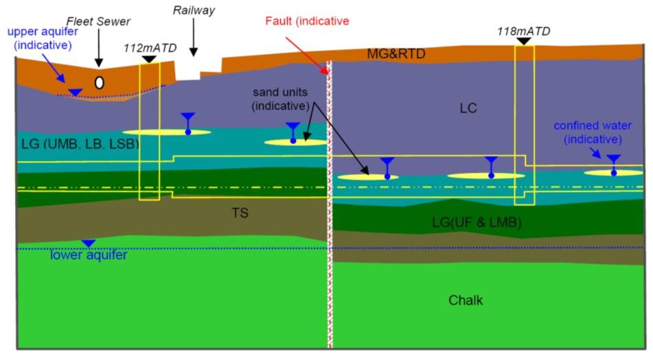
Figure 3 – Indicative geology anticipated in vicinity of Farringdon station
Strata Thickness
(m)
Typical Description Made Ground (MG) 2 to 4.5 Variable Alluvium
(ALL)
1.5 Soft to firm dark grey and grey brown sandy slightly gravely organic silty CLAY. River Terrace Deposits
(RTD)
1 to 2 Medium dense orange brown fine to coarse SAND/GRAVEL and rare cobbles of flint. London Clay
(LC)
5 to 23 Firm to very stiff fissured CLAY with silt partings and laminations. Increase in silt partings and becoming slightly sandy in the A2 unit. Lambeth
Group
(LG)
Upper
Mottled Beds
(UMB)
6 to 7 Very stiff to hard (friable microfissured) very closely to extremely closely fissured light grey to blue grey mottled light brown and red sandy to very sandy silty CLAY. Laminated
Beds
(LMB)
1 to 2.5 Stiff to very stiff thinly laminated fissured grey to dark grey, sandy to slightly sandy, silty to very silty CLAY, with extremely to very closely spaced thin laminations of light grey slightly sandy silt. Lower Shelly
Clay
(LSC)
<1 Stiff to very stiff fissured thinly laminated to thinly bedded dark grey and grey, silty to locally very silty CLAY with occasional bands of light grey sandy silt. Frequent to shells and shell fragments. Lower
Mottled Beds
(LMB)
2 to 8 Stiff to very stiff multi-coloured extremely closely fissured silty to very silty, slightly to very sandy CLAY. Upnor Formation (UF) 2 to 5 Very stiff dark grey-green, brown very sandy silty CLAY, with occasional fine to coarse rounded flint gravel.
Very dense black rounded medium and coarse flint
GRAVEL
Very dense brown or green to dark green speckled clayey to very clayey silty fine to coarse SAND, with a little to much fine and medium rounded flint gravel.
Thanet Sand (TS) 3 to 11 Very dense grey green silty fine and medium SAND. Table 1 – Summary of strata through which SCL tunnelling will occur at Farringdon.
Sand Channels
Within the Lambeth Group there occur relict sand channel deposits related to the paeleo- environment present during the geological period of deposition, representing a series of meandering channels in an estuarine type environment. These channels vary in frequency, width, depth, length and infill material and, as a result, are spatially unpredictable and therefore problematic to identify by Ground Investigation (GI) with any degree of certainty. There are examples of large extensive channels, such as below Bond Street station, where identification and extrapolation is more certain. The size of channels identified at Farringdon however tend to be thinner, typically to a maximum thickness of 3m, less extensive and encountered variably throughout the Lambeth Group. These sand channels were the subject of various internal and collaborative workshops on how best to mitigate their presence in the tunnel alignment.
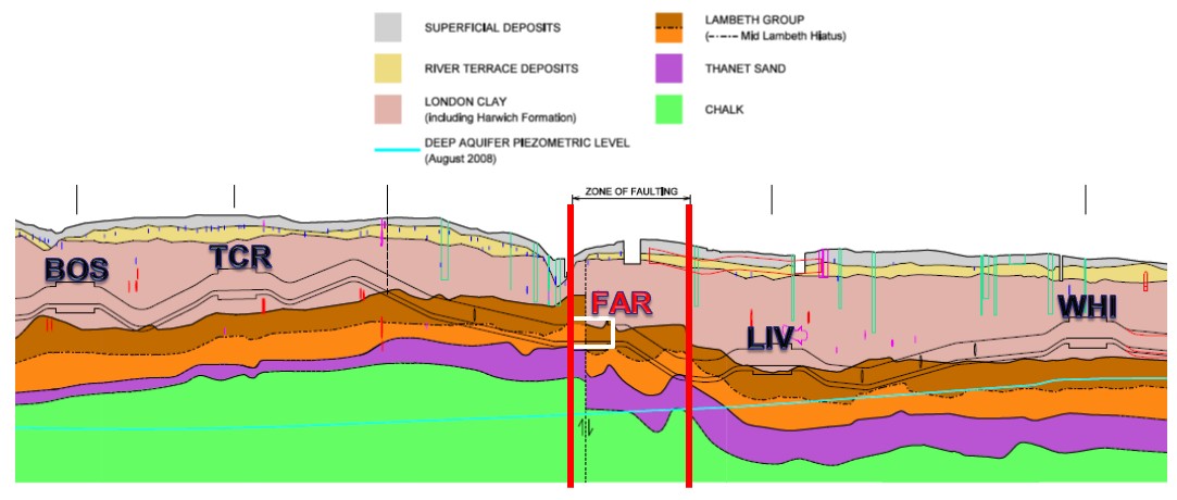
Faulting
Whilst faulting associated with major geological basement structural features was known to occur below London, the extensive GI programmes undertaken by Crossrail over twenty years has identified them to be more frequent than previously thought. The presence of faulting at Farringdon was postulated during early design phases due to the presence of the Fleet River alignment and the untypical change in strata levels across the station footprint. Subsequent phases of investigation however indicated that faulting was more widespread, with one major fault and many minor faults. Due to the concern at the effect of faulting and strata dislocation on tunnel excavation behaviour a separate independent review was undertaken by the British Geological Survey (BGS), combining the Crossrail GI database with that of the BGS to produce a detailed three dimensional model of the area. That review indicated the existence of at least four main faults, and four subsidiary faults, with throws typically of up to 4m (see Figure 4). As noted earlier the major fault, the “Smithfield Fault”, has a throw of 8m and directly juxtaposes Upper and Lower Lambeth Group strata within the tunnel face. Encountering these faults represents a high risk activity not present in any of the other stations in severity or persistence. Figure 4 summarises the proposed prescriptive
mitigation measures following much consideration on the most cost effective risk option to proceed. C121 employed the use of comparative risk assessments, peer reviews and expert panels to satisfy both CRL and the CAT 3 checker that an ALARP design was achieved.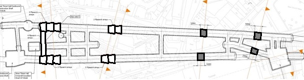
Figure 4 – Faulting in the vicinity of Farringdon Station
Notes:
Light shading – Grouted pipe arch
Dark shading – Grouted spilesGroundwater
The groundwater profile at Farringdon is typical for the London area comprising of an upper aquifer located in the superficial deposits and a lower aquifer within the Chalk, Thanet Sand and Upnor Formation. The historical effects of groundwater abstraction from the Lower Aquifer has resulted in an underdrained profile with pore pressures within the Thanet Sand and Upnor Formation being much lower than those above in the London Clay and upper Lambeth Group. Due to the dislocation of strata across the main Smithfield Fault the effects of underdrainage are different to the west and east. The current profiles are shown in Figure 5 and indicate maximum pore pressures at platform tunnel level of 100kPa to the west of the fault and 150kPa to the east.
Ground Related Risks
Although the geology and groundwater conditions at Farringdon are not unusual for central London it is the requirement to undertake the station construction using the open face SCL technique that introduces greater ground risk. The need to control groundwater ingress and pressures where granular materials occur in an open face is paramount if stability is to be maintained prior to application of the sprayed concrete.
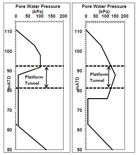
Figure 5 – Pore pressure distributions west & east of the Smithfield Fault
If the groundwater pressures at the face of the excavation are not reduced adequately they would cause instability of any sand layer resulting in a tendency for the sand to run into the excavation. If the granular strata comprise a significant proportion of the face then direct face instability can occur. In situations where minor sand/silt strata occur (such as laminae) the wash in of granular material may cause local undermining of the face and subsequent indirect instability. Any such loss of material from the face could trigger a fall of ground from the face, overbreak and promote greater than anticipated settlement. In addition it can result in poor working conditions which are unacceptable on health and safety grounds.
The extent of the risk and the form of the mitigation will depend on a number of variables:
• The size of the sand units that controls the quantity of potential stored water;
• Their permeability which controls the rate of water inflow;
• Their ability to recharge which controls the time for which inflow may occur,
• The magnitude of the pore water pressures present which again affects the amount of inflow, and
• The location of the sand channel in relation to the tunnel excavation profileThe majority of previous SCL works undertaken in London have been undertaken within the relatively uniform and dry London Clay. Similarly for Crossrail the majority of SCL to be undertaken at other locations will be within the London Clay where the potential for water bearing granular materials only occurs at depth below invert level. The associated groundwater risk in these conditions is low and related to the potential for invert heave. At Farringdon however the Lambeth Group contains granular water bearing materials that, because of the faulted strata dislocation, may occur at any point around the tunnel periphery and in the tunnel face. As such the risk of water induced face instability is a particular site specific issue. The greater risk of groundwater induced instability is highlighted by a simple comparison of the number of wells allocated during tender design which is summarised in Table 2.
Station Geology Well Allowance Surface Sites In-tunnel Bond Street London Clay None 140 Tottenham Court Road London Clay None 120 Farringdon Lambeth Group 50 3250 Liverpool Street London Clay & Upper Lambeth Group 28 850 Whitechapel London Clay None 400 Table 2 – Summary of SCL station well quantities at Contract tender
Faced with the prospect of encountering these highly variable ground conditions, C121 produced a design which aimed to address the main risk of encountering the isolated pockets of potentially water bearing sand lenses. Many options were considered but the chosen method for providing a robust solution to the problem was extensive use of in-tunnel and surface depressurisation targeting the intermittent variable sand lenses and underpins the rest of the design at Farringdon.
As noted earlier Farringdon also harbours a further complication: widespread faulting. The major Smithfield fault essentially dissects the station in half which means the west of the station has different geology to the east, the former representing more pessimistic tunnelling conditions – this is recognised in the prescriptive pre-support shown on Figure 4. Coupled with the already challenging ground conditions, the faulting adds a further dimension to the complexity for open face tunnelling. In particular faulting can result in localised increased fissuring, presence of persistent polished surfaces (colloquially termed “greasybacks”), softening and potential pathway for groundwater ingress. Therefore, in addition to the depressurisation specified, further ground treatment was proposed to allow safe construction through the faulted areas, which in this case amounted to proposed use of pipe arches west of Smithfield fault and grouted spiles to the east, in the crown of the tunnels. The difference in methodology being related to the different strata expected to be present at crown level either side of the fault.
Depressurisation
In order to address the critical groundwater risk an extensive investigation and depressurisation scheme was developed combining both surface and in-tunnel works. Farringdon Station is located in a congested area and the potential to maximise use of surface well sites is extremely constrained and cannot solely be used to address the risk. It is not therefore possible to confidently identify and depressurise all water bearing materials by surface works alone. To adequately reduce the level of risk there is a need to undertake SCL excavation with a degree of confidence that unexpected granular materials are unlikely to be encountered. In order that this risk can be maintained ALARP there is a requirement that in-tunnel investigation works are comprehensive (see indicative Figure 5). In order to achieve that level of acceptable risk the in-tunnel investigation needs to consider the following:
• Different investigation hole layouts related to different tunnel dimensions and excavation sequences.
• Provision of adequate investigated ground coverage ahead, and around the tunnel profile.
• Adoption of a method of investigation that can identify changes in strata that would typically be missed by conventional open holed probing techniques.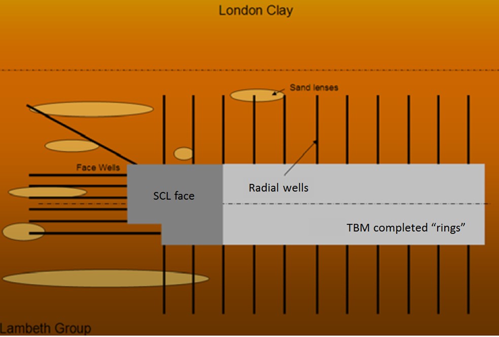
Figure 6 – Indicative schematic showing depressurisation for an SCL / TBM tunnel and sand lenses
The key difference between a closed face TBM pilot tunnel and a SCL pilot is the need to investigate ahead of the advancing face to ensure no “surprises” are encountered in the advancing face (Figure 6).
Given the impersistent channelised nature of the sand units, the drilling is considered to be of an investigatory nature and the findings of the investigation drilling will determine the subsequent risk and course of action. It is not expected that all holes will encounter groundwater bearing sand that requires a subsequent well installation. Where potential risk is identified by initial investigation then wells will be installed and the pore pressure reduced to predetermined appropriate levels. The assessment, direction and implementation of these mitigation items would be controlled by the construction Shift Review Group (SRG) who has direct day to day experience of the construction performance and understanding of impacts on the Works.
Tunnel Construction Options Selection
Numerous studies were commissioned to interrogate an alternative design methodology for the platform tunnels. It was widely agreed that a pilot tunnel was required for the platform tunnels, with systematic depressurisation, but the method for constructing these pilots was challenged extensively. The conclusion of all these studies was that a “newly” purchased TBM, forming a segmentally lined pilot tunnel for the platform tunnels, was the preferred solution and therefore all other methods and their respective risk profiles were compared to this base case. The options initially considered as part of this process are summarised in Table 3. Alternatives 5 to 8 were rapidly assessed as being inappropriate and discounted, the remaining base case and alternatives 1 to 4 were then carried forward for more detailed comparative assessment.
The enlargement of the platform tunnels from the pilot was also considered for each option. However, for the purposes of comparison, safety of the enlargement was deemed to be equal for each option. There would generally be two different methods considered, one for a segmentally lined pilot tunnel and one for enlarging from an SCL tunnel. Neither presented a great challenge over the other, but it was agreed that the most critical component of enlargement would be the depressurisation. As long as the pilot tunnel construction method allowed sufficient depressurisation to take place for the platform tunnel to be constructed, the enlargement method was not considered to be a deciding factor.
Peer Review
C121 operated a system of internal peer reviews using a group of experienced senior tunnelling professionals that were independent of the project. Regular “challenge” meetings were undertaken for the C121 option proposals to be subject to open questioning. This process was invaluable in obtaining a range of informed options that were considered to address the known risks and be constructible. In addition Crossrail appointed an external independent panel of tunnelling experts that reviewed all aspects of tunnelling on Crossrail, the proposals for Farringdon being subject to frequent rigorous examination. These two levels of independent review provide additional confidence to the Client and external Stakeholders that risks are being managed in accordance with industry knowledge and precedent experience.
Health & Safety Review
In order that the assessment approach did not become dominated by the technical, commercial and programme aspects of the different options it was critical that the health and safety risks were not sidelined. Construction Design Management (CDM) risk assessments were used to understand the key risks for the chosen option and subject to monthly reviews by the Client CDM-C. This was the final rigorous assessment of the chosen solution, before which all options were compared comparatively to identify the lowest risk option. Both CRL and C121 combined very effectively to make safety the top consideration for Farringdon, despite the fact that there were clear delivery programme and cost concerns (since Farringdon is where the lines connect).
Option Description Base Case Pilot tunnels constructed using a “new” Earth Pressure Balance (EPB) tunnelling machine. Vacuum wells installed radially from the pilot tunnels. Pilot then enlarged by SCL to form the platform tunnels. Alternative 1 Pilot tunnels constructed using an open faced shield with depressurisation wells drilled ahead of the open face. Vacuum wells also installed radially from the pilot tunnels then the pilot tunnel enlarged by SCL to form the platform tunnels. Alternative 2 One pilot tunnel constructed using an open faced shield and the second constructed using SCL with wells drilled ahead of the open face in both.
Vacuum wells also installed radially from the pilot tunnels then the pilot tunnel enlarged by SCL to form the platform tunnels.
Alternative 3 Pilot tunnels constructed using SCL with wells drilled ahead of the open face. Vacuum wells also installed radially from the pilot tunnels then the pilot tunnel enlarged to form the platform tunnels. Alternative 4 Extending the X drive TBMs through Farringdon, so that pilot tunnels are constructed by the Running Tunnel TBMs. Vacuum wells installed radially from the pilot tunnels then the pilot tunnel enlarged by SCL to form the platform tunnels. Alternative 5 Pilot tunnels constructed using a ‘Bessac’ machine which supports the face with compressed air. Vacuum wells installed radially from the pilot tunnels then the pilot tunnel enlarged by SCL to form the platform tunnels.
Discounted because: The water in the Lambeth Group is generally within discrete sand pockets within the low permeability clay matrix. Many of these pockets are not connected to other permeable areas. Compressed air may not be effective in this type of ground. Rather than creating a high pressure area which acts against the water pressure, with local pockets of water bearing permeable material there is a risk that the air will displace the water within the sand lens and push the water into the face, resulting in an unstable excavated face. This results due to the compressed air not providing a variable pressure at the face to match the earth pressure (as an EPBM does).
Only one manufacturer produces machines of this type, ‘Bessac’ in France, and there is limited experience of their use, particularly in the UK.
Alternative 6 Constructing the platform tunnels ‘full size’ using a closed face TBM. No need for depressurisation wells.
Discounted because: The west ticket hall shafts would not accommodate installation of a closed face machine able to build the platform tunnels (approx..12.5m dia). Shaft enlargement could achieve this but at increased cost. Initial reviews showed that there insufficient space at the worksites for this.
The TBM segmental lining would require openings for cross passages and ventilation tunnels. The design requires that these are of significant width, typically 5m. Construction of openings of this size would require major structural elements to be installed and take considerable time.
Alternative 7 Improving the ground for construction of open face pilot tunnels using horizontal jet grouting.
Discounted because: Horizontal jet grouting could be used to stabilise the ground for construction of the platform tunnels, but given the uncertainties about the location of the sand channels it would need to be installed for the full length of both platform tunnels. This would require access for drill rigs and grouting equipment and would generate a significant volume of fluid cementitious spoil that would need to be removed from the tunnel. Except at the shafts at the west end of the station, access for installation is extremely difficult and there is limited UK experience.
Alternative 8 Improving the ground ahead of open face pilot tunnels using ground freezing.
Discounted because: Ground freezing has major installation issues (impacting on programme and cost). Although only a low percentage of the ground needs to be frozen, it would be necessary to install the pipes along the full length of the tunnels. Risk that unfrozen windows of ground may occur over the extended length.
Table 3 – Summary of construction options considered in risk analyses
Comparative Risk Assessments
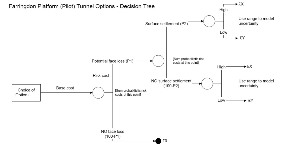
A useful tool employed for assessing risk is a Comparative Risk Assessment (CRA) which allows multiple options to be compared relative to each other. The fundamental principle is that a peer review(s) are undertaken whereby each option under consideration (in this particular situation, the base case compared to options 1 to 4) are rated numerically against one another. These options were originally compared at a high level on cost, programme and risk grounds to see if there was a standout “winner”, but it was clear that a more rigorous assessment was needed due to the nuance of each option presented. Therefore a more rigorous quantitative risk assessment was subsequently undertaken which for comparative purposes apportioned risk based costs leading to the following simple relationship and the decision tree shown in Figure 7:
Expected total cost (£) = Base cost(1) + Risk cost(2)
(1) Base cost includes the definite cost items associated with each option
(2) Risk cost includes the costs associated with potential risks of face loss associated with each option
Figure 7 – Decision tree for QRA
The estimated costs and probabilities of potential face loss (P1) and subsequent surface settlement (P2) were then analysed using a “monte-carlo” simulation to calculate the expected total risk based cost for each option. In essence this analysis is based on health and safety as it is relating to face loss and settlement, which affect risk to personnel in tunnel and third parties at the surface.
The base costs for each option were estimated to include all direct costs (for plant, equipment, labour and materials) associated with construction the pilot and related platform tunnels. Risk cost includes direct and indirect (schedule) costs associated with a loss of face risk event. The latter focussed on the risk of face loss (during construction of the pilot tunnel) and related ground settlement. This was seen as the most variable and significant risk for alternative options which impacted the construction cost. This risk was also seen as having significant consequences to the safety of construction workers and third parties.
Otherwise, all options were considered to have similar risk profiles and meet the same safety requirements including ALARP residual risk exposure.
Tunnel Instability Risk Cost Estimates
The potential for tunnel instability and the resultant costs can be divided into two broad types:
1) Additional construction costs associated with a minor loss of face material (up to a team agreed value of 50m3)
2) Third Party Liability (TPL) costs associated with a surface settlement due to major loss of face material (greater than 50m3).
Additional Construction Cost – Tunnel Face Loss
The principle mechanism for significant face loss was considered to be through ground water ingress from gravel/sand pockets in the Lambeth Group, or poor design/workmanship (e.g. dewatering scheme). Loss of ground is seen by insurers to be the highest risk due to higher reconstruction costs and frequency of occurrence (source; International Association of Engineering Insurers Paper Tunnel Boring Machine Applications in Soft Ground Conditions 2001).
Additional direct construction costs associated with tunnel face loss were estimated to include the direct cost of ground stabilisation, temporary measures, surveys, repairs, debris removal etc. Indirect construction costs associated with the works being halted were also estimated, the project taking longer to complete whilst the problem is resolved. The indirect costs were based on an increase in the preliminary costs associated with the additional time to complete the works.
It should be noted that mechanical failure or poor operation of the plant or equipment (other than dewatering) was not considered as a differentiating factor causing tunnel face loss.
Third Party Liability (TPL) Cost – Surface Settlement
TPL costs associated with surface settlement are one of the biggest issues when tunnelling in urban environment and at Farringdon this is particularly the case due to close proximity of utilities, operational railways and third party properties.
The potential costs associated with TPL loss can be grouped into two areas:
1) Losses associated with direct material damage or bodily injury of third parties, and
2) Consequential financial loss e.g. reduced revenue or profit associated with business interruption. Note that these losses are not typically covered by insurers and will be dependent on exclusions and level of cover required for a major event. It was estimated that the majority of TPL losses are up to £50m for all construction options considered.
A tenfold multiplier to the direct TPL cost was agreed with the expert team to represent the consequential third party financial losses.
Results of Cost Model Analysis
A “monte-carlo” simulation was performed to produce a distribution of expected total cost for each option using the derived cost and probability ranges. A resulting cumulative distribution sets out the confidence level in the expected outturn cost. The graphics in Figure 9 show the analysis results. The actual values are not particularly important, but the comparative values for each are.
The distribution shows that the SCL pilot option (red line) is the most cost effective option should a low level of confidence in the expected total cost be acceptable, that being only at a level of 35%. Above 35% confidence, use of the existing running tunnel EPBM’s (black line) was the most cost effective solution.
At approximately the 97% confidence level the existing and new TBM options (green line) have a similar cost/risk profile. A decision to adopt the use of the existing TBM’s however needed to be balanced against any disadvantages of the later start of SCL tunnel works due to the later arrival of the running tunnel EPBM’s resulting in overall project programme delay (not quantified comparatively in this analysis). That overriding project level risk was considered too high and therefore the seemingly more expensive option, based on mean total cost, of providing a bespoke EPBM was adopted.
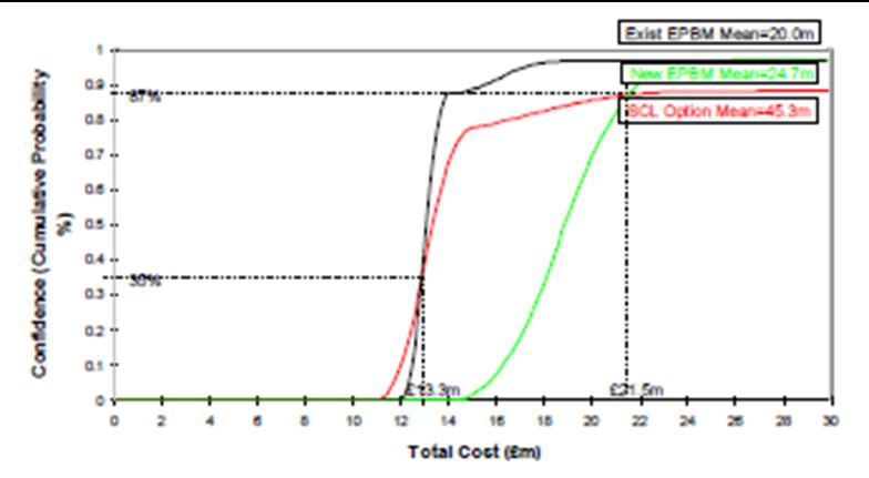
Figure 8 – Confidence level of total cost
The average expected total cost over the total cumulative range for each option is summarised in Table 4.
Option Cost Additional EPBM £24.7m Existing EPBM £20.0m* SCL £45.3m. Table 4 – Summary of average expected total cost
*Note that this price does not take into account associated programme delays
Summary
Farringdon Station has a number of ground related and project delivery constraints not seen anywhere else on the route which in combination make the SCL works a significant risk. The combination of faulting and water bearing intermittent sands are unique for Crossrail SCL locations and therefore the work carried out at Farringdon is bespoke and required a collaborative approach with all involved (e.g. Client, Stakeholders, designers etc). The major risks were considered and managed in a number of ways to cover health & safety, cost, programme and technical issues. To collate the often competing risks, rigorous assessments were undertaken which were subject to stringent internal and external review. Specifically, for the platform tunnel construction, a qualitative risk assessment tool was employed using a “monte carlo” statistical analysis to compare the range of potential outturn costs based on risks cost for different options. The outcome resulted in a seemingly expensive option being adopted but that which has a very high level of confidence in the outturn cost providing Crossrail with greater programme and cost certainty at a global project level.
At the time of writing this paper, OCI and VE options are being discussed with the contractor and therefore the employers design, presented herein, may be subject to change. However the tools employed illustrate how high risk elements of design can be discretised and analysed to find the lowest risk option amongst a selection of potential solutions. The success of this approach was dependent on a willing client and collaborative environment where the common goal was to reduce risk at the heart of Crossrail. By having these key components in place, it was possible to develop a base line design which can be considered ALARP – which in central London, with thousands of people potentially affected and millions of pounds at stake, was exactly what Farringdon required.
-
Authors

Andrew Davis
Geotechnical Team Leader C121 Mott MacDonald
Phillip Duarte CEng MICE - Mott MacDonald
Design Team Leader C121 Mott MacDonald