Fire design strategy in permanent tunnel linings (secondary linings)
Document
type: Technical Paper
Author:
Jose Suarez Diaz MSc CEng MICE, ICE Publishing
Publication
Date: 09/07/2018
-
Read the full document
1 Introduction
The design of sprayed concrete and cast in situ linings, with both SFRC (steel fibre reinforced concrete) and RC (reinforced concrete), against fire load as an accidental situation, is included into the Crossrail C121 contract that has been undertaken by Mott MacDonald. The C121 contract is basically described as the engineering services for the SCL structural design of the following underground stations and shafts: Whitechapel Station, Liverpool Street Station, Farringdon Station, Tottenham Court Road Station, Bond Street Station, Eleanor Street Shaft, Stepney Green Shaft and Fisher Street Shaft.
The fire response of steel fibres reinforced concrete (SFRC) and reinforced concrete (RC) members is influenced by the characteristics of constituent materials, namely, concrete, steel fibres and reinforcing steel. These include thermal properties, mechanical properties, deformation properties, and material specific characteristics such as spalling in concrete. The complex behaviour of concrete under this extreme situation leads to a fire design methodology that is based on structural analyses and experimental tests of different liner configurations. Therefore this paper is divided in two main parts:
I. Structural analysis of sections with different configurations and a maximum spalling, as per specification KT24, to define:
1. The fire load as per the European Standards (EUREKA). The design fire load is determined in accordance with the requirements that are included into the Crossrail CEDS. Part 1. Introduction and General Requirements [5].
2. The mechanism of fire response in concrete. The temperature over the cross section over time during a fire.
3. The modelling process of the structural model, built in FEM (Finite Element Model). The structural model is built assuming:
a. A reduced equivalent section with the same flexural and axial stiffness as the liner at the peak of the fire. This equivalent section is determined in accordance with the effect of the long term loading conditions, the high temperature distribution across the thickness liner and its impact on the concrete, fibres and steel parameters. Therefore, a reduced stiffness is set up as per Eurocode 2 Part 1-2 [2] (Young Moduli and cross section – factoring mechanical properties at high temperatures).
b. A local cracking in zones where the fire load impact is larger (plastic hinges),
c. Thermal loads (expansive temperatures and gradients) acting in combination with other existing permanent loads, as per BS-EN-1991-1-2[1].
4. The structural capacity of the lining that is based on the equivalent section which is determined in the modelling process, and the factored stiffness parameters of concrete, fibres (and steel rebar) at high temperatures. Since the elevated temperatures significantly influence the mechanical properties of concrete encountered in fire situations, the stress strain relationships of the concrete, steel fibres and steel have to be factored in accordance with the temperature along the lining (A per Eurocode 2 Part 1-2 [2]). There are two stages of the structural design check:
a. During the fire event, based on ULS (ultimate limited state accidental combination) with the equivalent structural section (reduced section including spalling) and reduced strength and stiffness parameters as per Eurocode 2 Part 1 2 [2].
b. Post-fire check (cooling down process after the fire event) based on ULS (ultimate limited state where all permanent loads and material factors are accordingly factored as per SCL Numerical Modelling Guideline). Furthermore, the full section minus the spalling, is deemed at the stage, and the stiffness parameters of all materials are set in normal conditions.
II. Evaluation of fire tests campaign on site:
The capacity of a structure to withstand load during a fire is called its fire resistance. This fire resistance can be substantially reduced when concrete cross-section is reduced due to the phenomenon of spalling during a fire event. Thus, spalling can be defined as a thermal instability that induces to flaking off of concrete that occurs when this is exposed to fire.
Since the spalling in concrete is a complex physical and chemical phenomenon that depends on many factors such a moisture content, porosity, permeability, type of aggregates, water / cement ratio, etc., it is really difficult to evaluate through analytical methods, thus, exclusively experimental methods based on fire tests with different specimens can lead to achieve more accurate results.
The fire tests campaign assessment focuses on the evaluation of the different configurations of liners regarding to the spalling. The fire test aims to get a maximum spalling that has not exceeded the spalling required in the specification KT24 – Fire testing for SCL works.
This fire design methodology gathers a set of fire tests assessments and complementary analysis of the critical sections (sections with a limited spalling) with the aim of ensuring a structural integrity during an enough period of time to allow self-rescue, evacuation of passengers and staff, and the linings reparation without any risk of structural collapse.
2 Structural analysis in tunnel linings during a fire event
The analysis procedure is based on the simplified calculation methods, as per Eurocode 2 part 1-2 [2], which are based on the stiffness reduction of concrete sections at high temperatures. There are several simplified calculation methods that are described in Annex B of Eurocode 2, however they are only applicable for standard fire curve (ISO 843). Thus, an alternative simplified method has been developed with the aim of applying the Eureka fire curve impact on the lining in terms of axial and flexural stiffness reduction at high temperatures.
2.1 The fire resistance profile curves (as per EUREKA)
The design fire load is defined in accordance with the fire resistance requirements that are given in CR-STD-303-1 Part 1[10] clause 2.2.4. Fire Resistance:
“The running tunnel lining design shall meet the RABT-ZTV (EUREKA) fire resistance profile curve, which applies to all tunnels, irrespective to their length. The fire performance of the finished tunnel shall withstand the specified temperature for the specified duration of time”.
In recent years a great deal of research has taken place internationally to ascertain the types of fire which could occur in tunnel and underground spaces. As a consequence of the data obtained from these tests, a series of time/temperature curves for the various exposures have been developed as detailed in Figure 1.
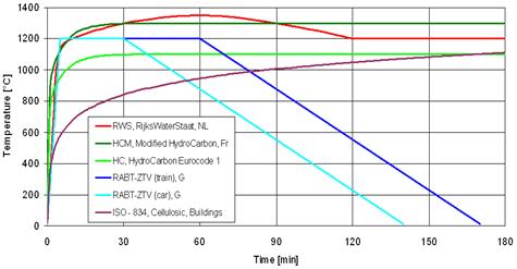
Figure 1. Temperature/time fire curves
The development of the RABT curve was undertaken in Germany. These curves were the results of a series of test programmes such as the Eureka project. The specified EUREKA fire curve (RABT-ZTV (train), used on Crossrail, is shown below:

Figure 2. RABT-ZTV (train) fire curve
2.2 Heat transfer in concrete linings during fire events. Thermal parameters
The mechanical properties of the concrete lining are significantly influenced by the elevated temperatures during a fire event. The temperature over the cross section Θ(x) for each time increment determines which part of the cross section can be structurally affected by the fire load. Therefore, the distribution of temperature over a concrete cross section is important to evaluate the structural capacity of tunnel linings under the accidental situation of a fire event. The temperature distribution in the lining can be obtained determining a thermal profile across the concrete section in accordance with the specific thermal parameters that are defined below:
2.2.1 Thermal conductivity of concrete
The thermal conductivity of concrete, λc, is defined as the rate at which heat will be transported through it and hence the rate of heat loss. This parameter is deemed important when estimating temperature rise and temperature differentials in specific situations such as in the event of a fire.
The main factors influencing the thermal conductivity of concrete are listed below:
- The aggregate type.
- The aggregate volume – aggregate has a higher thermal conductivity than both cement and water.
- The moisture content – as concrete hydrates and dries, the space previously occupied by water empties and the conductivity reduces.
Eurocode 2 [2], clause 3.3 defines thermal conductivity at high temperatures between two bound values. The lower bound is set to temperatures measured in concrete structures exposed to fire and the upper curve is set to temperatures measured in composite structures (steel – concrete) during fire exposure. The lower bound has been adopted in the structural analysis, and is defined for normal weight concrete as follow:
λc = 1.36 – 0.136 (θ/100) + 0.0057 (θ/100)2 W/m K for 20°C≤ θ ≤ 1200°C (1)
where θ is the concrete temperature.
Regarding to mixes with fibres, thermal conductivity for fibre – reinforced concretes (with both steel and polypropylene fibres) almost follow a similar trend as that of plain concrete. Thus, there is no significant effect of fibres on thermal conductivity of concrete in a 20–800°C temperature range [4].
2.2.2 Specific heat
Specific heat can be defined as the amount of heat per unit mass that is required to change the temperature of a material by one degree, and is often expressed in terms of thermal capacity, which is the product of specific heat and density. The specific heat of concrete, cp , is a parameter that is required in the determination of thermal diffusivity, D ,(through the expression D = λc /cp ρ ), used in thermal analysis. The range of values for concrete may vary from 0.75 to 1.17kJ/kg oC.
The specific heat is highly dependent on moisture content and considerably increases with higher water to cement ratio. Eurocode 2 [2] defines, in Clause 3.2.2, the specific heat cp (θ) of dry concrete (u = 0%) for both types of aggregates, siliceous and calcareous.
The relationship between specific heat and temperature for SFRC and RC tunnel linings with moisture content equal to 3% of concrete weight is illustrated below:
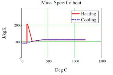
Figure 3. Mass specific heat (Farringdon Analysis – C121)
2.2.3 Mass loss and volumetric specific heat
Density of concrete varies with the temperature, and is strongly influenced by the water loss. The formulation that describes this change of density with the temperature is included in the clause 3.2.2 of Eurocode 2 [2]. This change of density (mass loss) affects the volumetric specific heat. For example, the variation of volumetric specific heat cv(θ) (product of ρ(θ) and cp(θ)) is described below in Figure 4 for SFCR and RC with a moisture content of 3% by weight and a density of 2400 kg/m3.
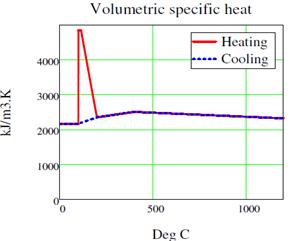
Figure 4. Volumetric specific heat (Farringdon Analysis – C121)
2.2.4 Algorithm of temperature distribution through concrete lining (under Eureka RABT – ZTV fire curve).
A complex algorithm has been developed aiming to represent the thermal profile in concrete linings under the influence of an accidental situation of fire where a fuel produces a release of heat that matches the RABT-ZTV (train) fire curve in terms of temperature. This algorithm defines the different mechanisms of heat transfer from the source of heat up to the reduced concrete lining once the spalling has taken place. Algorithm structure developed by C121 design team:
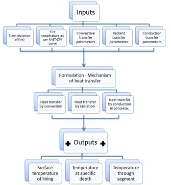
Figure 5. Thermal profile algorithm
To illustrate this heat transfer through the lining, the Bond Street Station analysis has been used as an example and it is detailed below:
- Coefficient of heat transfer by convection: hhtc = 35 W/(m2 K)
- Ambient temperature: θ0 = 20 K
- Configuration factor: ϕc = 1
- Furnace and surface emissivity: εf = 1 εm = 0.8
- Stephan Bolzmann constant: σ = 5.67 10-8 W/m2 K4
- Lining thickness: h = 300 mm.
- Spalling (as per fire test results) hs = 25 mm(KT24).
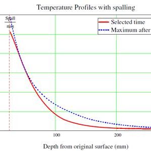
The following temperature profiles through the concrete lining are obtained with the resolution of the algorithm (Figures 6 and 7):
Figure 6: temperature profiles (Temperature vs. Time). Bond Street Station.
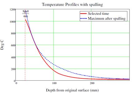
Figure 7: Temperature profile with spalling at Bond Street Station.
2.3 Performance of concrete liners at elevated temperatures as per Eurocode 2 [2]
The modelling process is defined in accordance with two main aspects:
- Definition of the geometry of the lining and restraint conditions using a structural spring beam model in FEM and,
- Calculation of the mechanical and thermal properties of concrete at elevated temperatures and the fire load acting on the lining.
2.3.1 The structural spring beam model in FEM.
A 2D model is built in STAAD Pro (FEM software) with the following properties:
- Tunnel lining geometry as per secondary lining geometry in platform tunnels (radius and thicknesses).
- The tunnel lining is radially supported by 1 meter length concrete spring beams that represent the interaction ground – lining. These spring beams have an axial stiffness equal to the axial stiffness of ground that confines each spring beam, and are only working in compression (representing the passive pressure of the tunnel lining over the ground). See Figure 8 below:

Figure 8: Structural spring beam model in 2D
- Concrete grade C32/40 is used in most SCL models. Farringdon models are the only ones with a concrete grade equal to C50/60.
- Plastic analysis. Since the most critical cases for the performance of the lining would be severely affected by fire intensity at crown and sides, a set of plastic hinges are allowed to be formed on those critical zones. According to this assumption, the lining will be cracking during the fire event, and furthermore, this cracking will remain after the fire. Therefore, the same cracking status is set up in the post fire situation.
Two situations are assessed:
- Accidental situation (fire): Determine ULS accidental load combination (from Eurocode 1-2[1] Section 4) due to a fire event where the rest of the permanent loads (Self-weight, ground pressure, pore water pressure, etc) are combined with the fire load (temperature and gradient) and factored by γL = 1.0. Furthermore, to take into account the effect of fire on actions, multiply the load effects Ed from the permanent ULS STR with the reduction factor ηfi, which can commonly be taken as 0.7 (Eurocode 2[2] clause 2.4.2 (3) Note 2).
- Post fire situation (cooling down process): Once the fire is over, the tunnel lining will remain cracked but is still withstanding all permanent loads. Therefore, a specific ULS load combination is set up where all permanent loads are acting on the lining with factors as per CR-STD-303-1[5] and Eurocode 2[3]. This assessment aims to guarantee a structural integrity of the lining during the reparation process.
2.3.2 Mechanical properties and deformation of concrete at elevated temperatures.
The mechanical properties of concrete, with relevant influence in fire resistance design, are compressive strength, tensile strength, elastic modulus, and stress-strain response in compression. These parameters, all together with deformation parameters, are used to calculate the equivalent structural section under fire conditions. All numerical values of these parameters, at elevated temperatures, are determined according to Eurocode 2[2].
2.3.3 Compressive strength
The variation in compressive strength of concrete at high-temperatures is quite high. According to Eurocode 2[2], the strength and deformation properties of uniaxially stressed concrete at elevated temperatures shall be obtained from the stress-strain relationships. These relationships at elevated temperatures are described below:

(2)
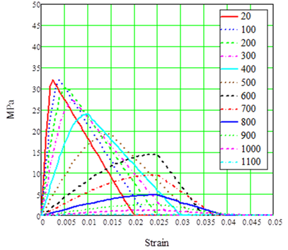
Figure 9. Stress / strain relationships for concrete (RC and SFRC)
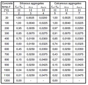
This graph is built considering values from table 1 that is taken from Eurocode 2[2].
Table 1. Values for the main parameters of the stress-strain relationships of normal weight concrete with siliceous or calcareous aggregates concrete at elevated temperatures
2.3.4 Tensile strength of concrete
Since the tensile strength of concrete is much lower than that of its compressive strength, it should be ignored (as per Eurocode 2[2] in a conservative approach) in strength calculations at ambient and elevated temperatures.
However, in SFRC linings, the addition of steel fibres to concrete enhances its tensile strength and the increase can be up to 50% higher at ambient temperature [4]. Furthermore, the tensile strength of SFRC decreases at a lower rate than that of plain concrete throughout the temperature range of 20–800°C [4]. This increased tensile strength can delay the propagation of cracks in steel fibre-reinforced concrete structural members and is highly beneficial when the member is subjected to bending stresses. The steel fibres retain their tensile capacity up to 100oC, after this temperature the tensile strength decreases lineally until cero at 600oC.
Therefore, the tensile strength of SFRC at elevated temperatures is factored by kc,t (θ) as follows:
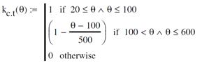 (3)
(3)
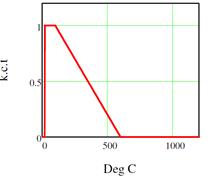
Figure 10. Tensile strength factor at high temperatures
Thus, the strain/strain relations for SFRC concrete in tension at high temperatures becomes as is described in figure 10:

Figure 11. tensile stress / strain relationships for SFRC
2.3.5 Tensile strength of steel
According to Eurocode 2[2], the tensile strength and deformation of reinforcing steel at elevated temperatures shall be obtained from the stress-strain relationships specified below in figure 11 and table 2. These stress-strain relationships are determined by three parameters:
- The slope of linear elastic range Es,θ
- The proportional limit fsp,θ
- The maximum stress level fsy,θ
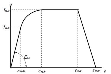
Figure 12: Stress-strain relationships of reinforcing steel at elevated temperatures
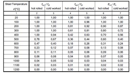
Table 2. Class N values for the parameters of the stress-strain relationship of hot rolled and cold worked reinforcing steel at elevated temperatures.
The following parameters are assumed in analysis:
- Reinforcing bars class N.
- Cold worked.
- Strains: εsy,θ = 0.02 εst,θ = 0.05 εsu,θ = 0.2
The reinforcement stresses at high temperatures according to these parameters are plotted in figure 13.
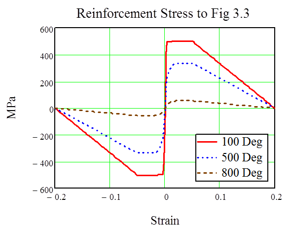
Figure 13: Reinforcement stress at high temperatures as per table 2.
2.3.6 Elastic Modulus
Since the stress/strain relationships vary considerably at elevated temperature, the modulus of elasticity decreases rapidly with the rise of temperature (see Figure 14 [4]).
Figure 14. Variation in elastic modulus of concrete as a function of temperature (NSC-Normal Strength Concrete)[4]
2.3.7 Thermal expansion
The thermal expansion of concrete increases from zero at ambient temperature to about 1.4% at 700°C and then generally remains constant through 1000°C. This increase is important in the 20–700°C temperature range due to high thermal expansion of constituent aggregates and cement paste in concrete. The thermal elongation of concrete as per Eurocode 2[2], considering siliceous aggregates, is defined below:

(4)
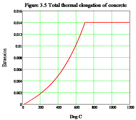
Figure 15. Thermal elongation of concrete as per Eurocode 2 (Siliceous aggregates)
Furthermore, the thermal strain and stress through linings has been determined deeming the variation of temperature with depth and its mechanical impact in term of stiffness.

Figure 16. Thermal Strain vs. Depth
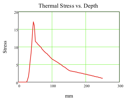
Figure 17. Thermal Stress vs. Depth
2.4 Structural modelling by FEM Equivalent sections
2.4.1 Equivalent concrete section at elevated temperatures
The equivalent concrete section is a reduced section that is determined according to the reduced stiffness at elevated temperature. This equivalent cross section, used in the FEM model, is determined for each case calculating the following parameters:
- Temperature over the cross section Θ(x) for each time step as per Section 2.2 of this paper considering 25 mm spalling as per specification KT24. To illustrate this temperature distribution, the Bond Street case is detailed in figure 18:
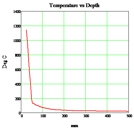
Figure 18. Temperature vs. Depth
- Thermal strain over the cross section ε(Θ) as per Section 2.3.7 of this paper.
- Concrete compressive and tensile strength that is dependent of local strain as well as on local temperature. The value of σ(ε,Θ) is evaluated according to Section 2.3.3 and 2.3.4 of this paper.
The determination of the equivalent cross section structurally competent (clamped liner) was carried out as follows:
- Initially, it is necessary to calculate the axial force increment due to the fire load. Thus, the following steps have to be followed:
a. Determination the initial liner axial load (N0) allowing for spall according to the long term loading condition (ULS combinations in the FEM model). This axial load is used as an input in this analysis (for setting up the initial conditions before the fire event).
b. This initial axial load allows determining the initial strain and stress on the liner.
c. Once the fire load is acting, strains and stress on the clamped liner start to increase in accordance with the temperature distribution across the thickness from fire face to ground face. The stress distribution across the spalled liner is described as follow:

Figure 19. Stress distribution across the spalled liner
d. The total axial force acting on the clamped section is:
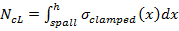
(Due to ground loads in long term plus fire load.)
(5)
e. Thus, the axial force increment due to the fire is as follows:
 (6)
(6)- Calculation of the axial stiffness of the clamped liner. To determine the axial stiffness a strain increment is used as is described below:
a. Axial force for a given strain increment:
 (7)
(7)b. The axial stiffness can be determined in accordance with a nominal strain increment equal to δε, and setting up the following relation:
 (8)
(8)- Calculation of the flexural stiffness of the clamped liner. This calculation has the same approach as the calculation of the axial stiffness; however, in this case, the increment is straight applied on the curvature.
a. Initially the elastic centroid has to be calculated for being used in the formulation that defines the flexural stiffness. The elastic centroid is determined according to the following relation of axial stiffness across the liner:
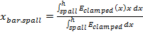 (9)
(9)b. Moreover, the flexural force on the clamped section can be calculated as per this elastic centroid:

(10)
c. The bending moment, for a given curvature change, is determined in accordance with the elastic centroid, and the stress / strain relation that results of this change of curvature on the clamped section:

(11)
d. The flexural stiffness is evaluated according to a nominal change of curvature, δρ, as follows:
(12)
- Finally, the equivalent liner parameters that are used in the FEM model and the design charts are calculated in accordance the axial and the flexural stiffness of the clamped section previously determined.
a. Equivalent thickness:

(13)
b. Equivalent Young Modulus of the concrete:

(14)
2.4.2 The fire loads in the FEM model
The fire loads are calculated considering the coefficient of thermal expansion of the concrete and the axial and the flexural forces previously calculated for the clamped section of the liner. These sorts of loads are posteriorly applied on the FEM model.
- The actual fire loads are expressed as a constant temperature load Δt and a linear temperature gradient tdiff based on the coefficient of thermal expansion of concrete αt at the reference temperature.
- The mean temperature rise in model for clamped axial force is obtained by

(15)
- The temperature gradient is obtained in accordance with the relationship between the flexural force of the clamped section that has previously been calculated, and the equivalent thickness of the liner. This relationship is set up assuming a linear elastic distribution of the thermal stresses across the equivalent clamped section as is described below:

(14)
Note that this assumption is exclusively applied on the thermal stress distribution to aim the determination of the temperature differential across liner for clamped flexural force. Moreover, SFRC liners under this fire loading condition can easily crack during the heating and cooling down process of a fire event.
The FEM models are initially built without cracking, however, once the structural capacity is evaluated in term of bending moments / axial forces relations obtained from the model outputs, there has been demonstrated the need of doing a plastic analysis to control bending moments and rotations in a realistic situation of cracked liner under fire event.
- The temperature differential across the liner is expressed as follows:

(16)
The FEM model result as is shown in figure 20:
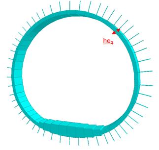
Figure 20. FEM model with equivalent reduced section
2.5 The fire design resistance as per Eurocode 2 Part 1 -1 [3] and RILEM TC 162-TDF: ‘Test and design methods for steel fibre reinforced concrete’
The resistance of the reduced section will be evaluated using the design charts (bending moment / axial forces relations) that have been produced in accordance with the standards Eurocode 2 and RILEM TC162 with the aim of evaluating the structural capacity of an equivalent section with different configurations: SFRC (steel fibres reinforced concrete) or RC (reinforced concrete). Thus, the design check charts deem the structural contribution of the fibres.
2.5.1 The structural design check during the fire event
The design check during the fire event aims to evaluate the structural capacity of the reduced section (clamped section) with all those parameters that have been determined as per section 2.4.1 of this paper.
The design chart has to be modified changing some important parameters according to the new equivalent clamped liner. These modifications are listed below:
- SFRC liners: the concrete grade is modified with the aim of providing the equivalent Young Moduli according to calculations carried out in section 2.4.1 of this paper. The thickness must also be updated deeming the equivalent thickness of the clamped section.
- RC liners: Besides of the liner thickness and the concrete Young moduli modifications, the reinforcement steel parameters have to be modified as follow:
- Determination of the temperature of reinforcing bars, according to the cover and the parameters presented in Section 2.3.5 of this paper.
- Factoring of the normal elastic modulus of steel according to the high temperature at cover section.
- Factoring of the tensile strength of the steel as per the high temperature at cover section.
- The partial safety factor γM,fi, in fire situation, is 1 for mechanical and thermal properties of concrete, fibres and reinforcing (as per clause 2.3 [2]).
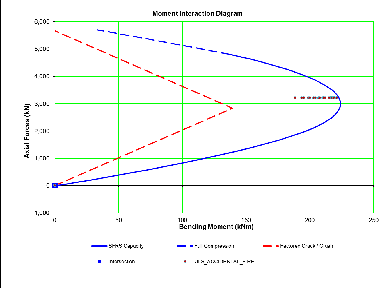
Thus, the structural capacity of the lining under fire conditions is evaluated considering the outputs from the FEM analysis and the amended design chart (see Figure 21). The integrity of the lining is guaranteed whenever all the FEM outputs are inside of the capacity lining of the design chart. Since bending moments that are obtained in some areas (crown and upper side) of elastic models are quite large, FEM outputs are normally out of the capacity curve, hence some cracks might easily arise on the lining. According to this, plastic hinges are included on those zones in the FEM model aiming to model these potential cracking zones, an additional rotation check is carried out to avoid cracking and crushing issues that might compromise the integrity of the lining.

Figure 21. Design chart
2.5.2 The post-fire structural design check. Cooling down process.
The post-fire structural design is to ensure a repairing process without any risk of collapse of the tunnel lining. This stage of design deems the following aspects:
- Linings remain cracked as per fire condition as a consequence of the cooling down process of the concrete; therefore the FEM model remains with plastic hinges. A plastic analysis is carried out by FEM.
- Actions are factored assuming normal conditions (ambient temperature). Fire load are eliminated in the ULS load combinations. Actions and ULS load combination are defined as per C121 SCL Numerical Modelling Guidelines.
- Reduction material factors are set up as per Eurocode 2 [3].
- Lining thickness is uniquely reduced by the spalling (from fire tests).
The structural design check is carried out using the Eurocode 2 design charts for ULS combinations, and posteriorly, a similar rotation check is undertaken according the type of concrete (RC or SFRC).
2.5.3 Assessment of FEM analysis results.
The FEM structural analyses of the most critical cases according to the maximum spalling (as per the specification KT24) have led to conclude the following important design aspects:
- SFRC liners have enough capacity with a maximum spalling of 25 mm.
- RC linings have equally enough structural capacity with a maximum spalling up to 25 mm.
- The polypropylene fibres contribution has been ignored in these analyses.
3 Evaluation of the fire tests campaign
The evaluation of the fire tests campaign is mainly focused on the spalling extension depths obtained on these tests, and if this spalling complies with the requirement of the specification KT24.
3.1 The phenomena of spalling in concrete
Concrete presents low heat conductivity and a significant high density what means a slow penetration of heat in all concrete structures like SCL in tunnels. However, in steady fires during a period of time, a critical region is formed where temperatures are circa 200ºC [4]. Cracks are opened in this region which lead to the flaking off (spalling) of concrete from the surface. Fire induces spalling in concrete mainly due to the low permeability of concrete and the moisture migration in concrete at high temperatures.
The spalling extension depends on many factors as strength, density, porosity, permeability, fire intensity, aggregate type, relative humidity, amount of silica fume, and other admixtures. Furthermore, the latest fire testing indicates that apart from these material characteristics factors there are other important factors influencing spalling such as the following:
- In thicker sections, the restraint from colder sides of the structural member leads to more fire spalling.
- Temperatures where the surface is flaking off can be < 200°C which rules out the correlation between pore pressure and fire spalling.
- Compressive loading conditions induces to increased fire spalling
Therefore, the prediction of spalling is complicated based on analytical methods, so experimental methods (fire tests) achieve the most accurate results. There is a lot of experience in fire tests for reinforced concrete, and according to this, it is conservatively accepted that a maximum spalling of 25 mm in tunnel linings with a moisture content circa 3% will take place. Eurocode 2-1-2 [2] states that spalling is unlikely to occur in normal concrete when the level of moisture content is around 3% by weight. However, the moisture content can be variable in tunnel linings, and other factors might also have negative influence, thus the specification for the sprayed concrete lined tunnels was written such that the concrete mix could only be approved for use on site if subjected to a fire test and the experienced spalling was not more than 25 mm of the lining. The assumed extent of spalling was confirmed through the fire test results.
C. Féron, C. Larive & G. Chatenoud [6] have suggested that spalling, in SCL, can be minimized by adding polypropylene fibres to the mix. Polypropylene fibres can melt when temperatures in concrete reach about 160–170°C producing pores in concrete that are sufficient for enhancing the permeability and relieving moisture content in the concrete. The Crossrail designs have considered a polypropylene fibre content between 1 Kg/m3 to 2 Kg/m3.
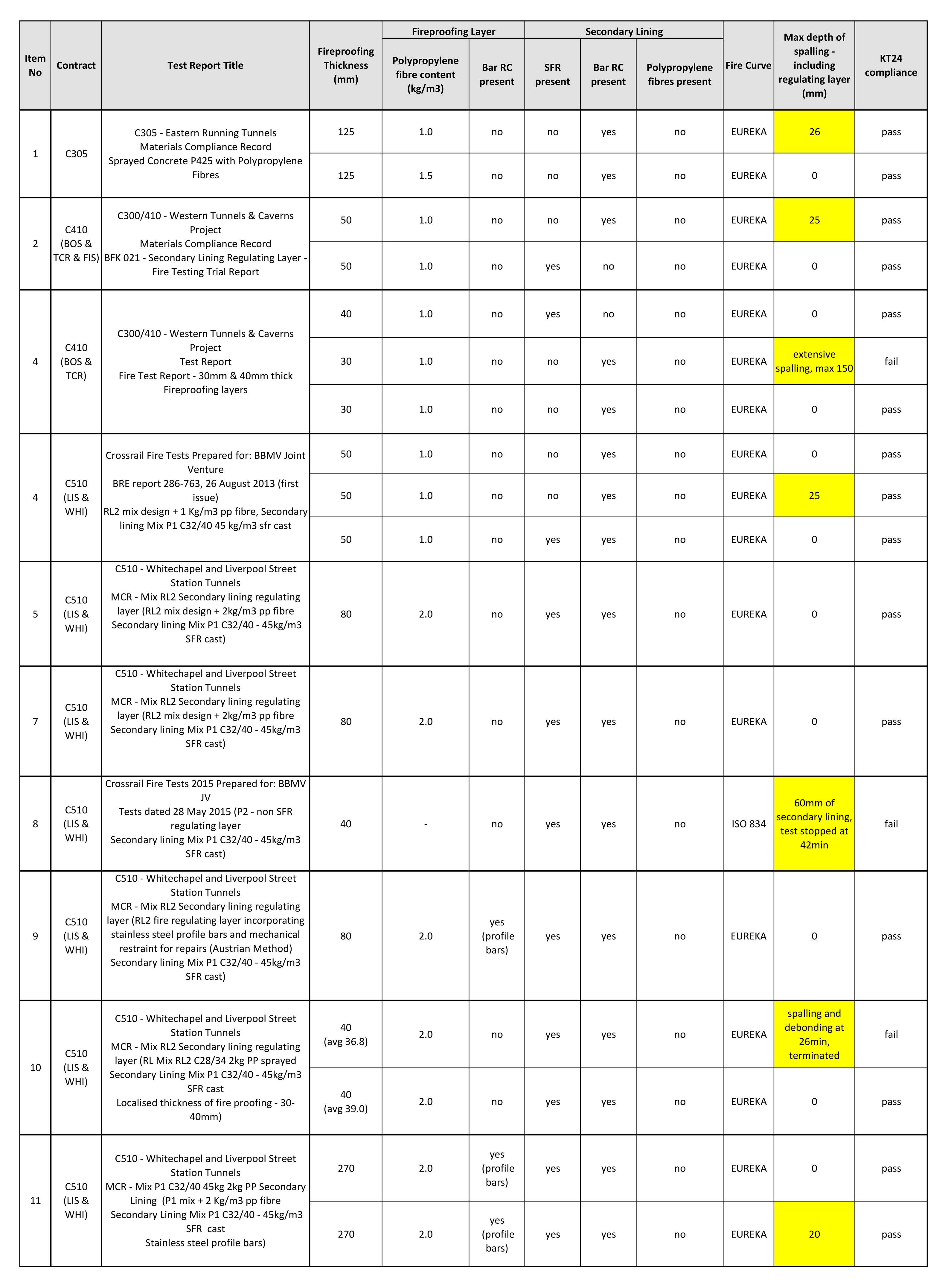
3.2 Fire test results
The Crossrail fire tests campaign characteristics are described below in table 3:
Table 3. Fire testing summary for SFRC and RC liners
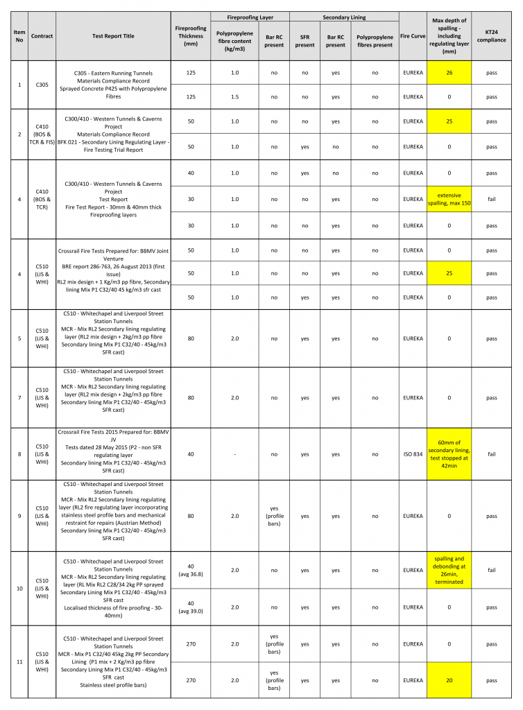
As described above, different configurations of linings have been set up aiming to evaluate their compliance with the specification and therefore their appropriate suitability under a fire scenario. As it can be seen in Table 1, the most critical cases are highlighted in yellow, and those configurations of liner with a spalling up to 25 mm were considered to be compliant and therefore appropriate for use on site.
4 Conclusions
Concrete tunnel linings suffer significant physicochemical changes at high temperatures during a fire event. These sorts of changes induce to deterioration of concrete properties, and introduce additional complexities, such as spalling, which is widely evaluated in the fire tests campaign, including the importance of the polypropylene fibres in the fire resistance of concrete tunnel linings. The Crossrail fire test results have confirmed good results when 1 kg/m3 of polypropylene fibre is used in the different configurations of liners.
Furthermore, the C121 fire design methodology evaluates, as an additional assessment, all the significant changes of the thermal, mechanical, and deformation properties that take place in concrete linings during a fire. This assessment, which complements the fire tests, is the structural analysis of equivalent reduced sections with a limited spalling as is required in the specification KT24, within the temperature range associated with Eureka fire curve (RABT-ZAV), and is based in Eurocode 2[2]. These analyses have demonstrated the structural competence of different configuration of linings with 25 mm of maximum spalling.
Therefore, the fire design methodology constitutes a reliable process of design based on two main pillars: The structural analyses, in accordance with Eurocodes, and fire test campaign, where results, both analytical and experimental, are conservative enough to guarantee the structural integrity of the lining during a period of time that includes the fire and post fire event. Furthermore, this methodology offers the possibility of evaluating different configurations of liners with different spalling in future projects.
5 Acknowledgements
The author would like to acknowledge the contributions and support of my colleagues in the development of the Fire Design Methodology in Mott MacDonald. I would like to give special thanks for their contributions to this paper: Alex Lowson, Daniel Reader, Christoph Eberle, Stephen Penfold, Rosa Diez, Chris Pound and Dave Harris.
6 References
[1] “EN 1991-1-2: actions on structures. Part 1-2: general actions—actions on structures exposed to fire,” Eurocode 1, Brussels, 2002.
[2] “EN, 1992-1-2: design of concrete structures. Part 1-2: general rules—structural fire design,” Eurocode 2 -1, Brussels, 2004.
[3] “EN, 1992-1-1: design of concrete structures. Part 1-1: general rules—General rules and rules for buildings” Eurocode 2-2, 2004.
[4] V. R. Kodur, “Fibre-reinforced concrete for enhancing structural fire resistance of columns,” Fibre-Structural Applications of Fibre-Reinforced Concrete, ACI SP-182, pp. 215–234, 1999.
[5] CR-STD-303-1 (Crossrail Civil Engineering Design Standard) Part 1 (Introduction and General Requirements).
[6] C. Féron, C. Larive & G. Chatenoud. Spalling of sprayed concrete under tunnels fire conditions. CETU, Bron, France. 2009.
-
Authors

Jose Suarez Diaz MSc CEng MICE - Mott MacDonald
C121 Design Manager