Fire and Water, the Crossrail Experience
Document
type: Technical Paper
Author:
Mike King BSc CEng MICE, ICE Publishing
Publication
Date: 30/09/2017
-
Read the full document
Introduction
The idea for an East-West rail link across London has its origins in the Regents Canal & Railway Company of the late 19th Century. The concept of the link went through several other evolutionary developments over the following 90 years including the post second world war Abercrombie Plan, leading up to the more recent 1974 London Rail Study where “Crossrail” was finally born. Had the scheme been built at any of these previous times we would probably be looking at a very different product to the one now showing its face to the world today, which uses the latest materials and technology to meet the demanding performance requirements imposed on the project. With a combination of a design life of 120 years and some exacting performance demands for the structures, for example the requirement to withstand the extremes of a 12000C fire and resist 40m head of external water pressure, the project has developed solutions based upon previous project experience and robust engineering to satisfy requirements that could be argued to require conflicting solutions for the materials in terms of their permeability at the very least.
This paper summarises the key aspects of the project including an overview of the strata that the tunnels were constructed in, and then presents the project requirements for the tunnel structures in terms of fire and water protection, and the tests undertaken to demonstrate compliance and allow acceptance of the completed structures by the eventual owners, railway regulators, operators and maintainers.
Overview of the scheme
General scheme
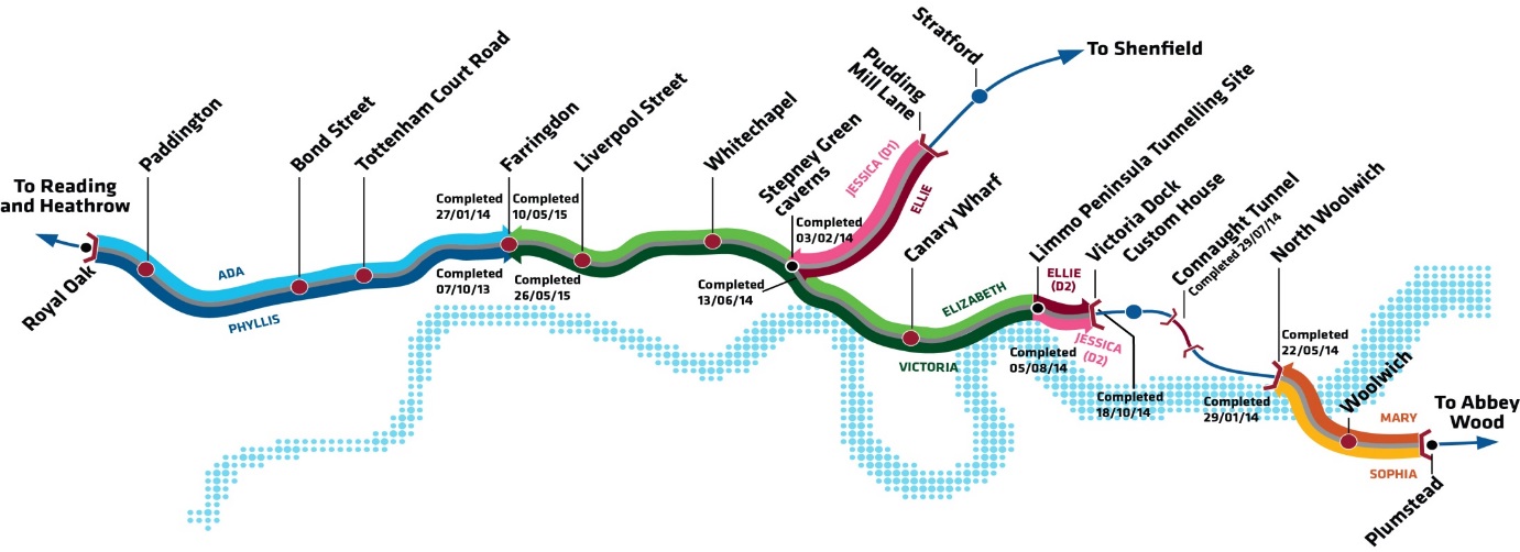
The Crossrail East-West link across London will provide a 10% increase in existing rail capacity in London enabling an additional 200 million journeys each year linking up major business centres and existing transportation interchanges beneath the congested and built-up city. The whole scheme extends from Reading in the West, to Shenfield and Abbey Wood in the East, but it is the central section from Royal Oak in West London to Plumstead and the Olympic Stadium in the East that contains the vast majority of the tunnelling works (see figure 1). The central section has now completed construction of the 42 km of major running tunnel structures in Precast Concrete Segmental Linings (PCL), constructed behind pressure balance tunnel boring machines. Sprayed Concrete Linings (SCL) and cast insitu linings within 5 new stations, 6 crossover and bifurcation caverns, and numerous access passages and crosspassages, adits and ventilation tunnels are due for completion later in 2016.

Figure 1 – Central tunnel section of Crossrail
The high capacity train service will operate up to 24 trains per hour and will bring an additional 1.5 million people within 45 minutes commuting distance of London’s key business districts.
The main tunnelling contracts with fire test and waterproofing test results discussed in this report are summarised in Table 1.
Table 1 – Summary of main tunnelling contracts with test results considered in this report
Contract No. Principal Contractors Main Construction elements with test results considered in this paper C300 BAM / Ferrovial / Kier PCL from Royal Oak to Farringdon
SCL at Fisher Street Crossover caverns
C305 Dragados / Sisk PCL from Victoria dock portal to Farringdon, and from Pudding Mill Lane to Stepney Green
SCL at Stepney Green bifurcation caverns and Limmo shaft
C310 Hochtief / Murphy PCL from Plumstead Portal to N. Woolwich Portal C410 BAM / Ferrovial / Kier SCL at Bond Street Station and Tottenham Court Road Station C435 BAM / Ferrovial / Kier SCL at Farringdon Station
Cast insitu at Farringdon Station
C510 Balfour Beatty / BeMo / Morgan Sindall / Vinci SCL at Liverpool Street Station, and Whitechapel Station and crossover caverns Geological setting
The geographic spread of Crossrail across London has meant that most of the strata beneath the city down into the underlying chalk have been encountered and traversed by the tunnels on the project. Starting from the west end of the central section, the tunnels are in the over-consolidated London Clay from Royal Oak to between Tottenham Court Road and Farringdon Stations. The London Clay is the favoured tunnelling medium in London where historically most of the tunnels across the city have been constructed up until the time of the introduction of the more advanced face pressure stabilising technologies now available on standard tunnel boring machines. Although containing some sand lenses and water which locally increases the permeability, the London Clay is a relatively impermeable and stable tunnelling medium. Further east towards the centre of the tunnelled section the tunnels and stations at times move down into the Lambeth Group, which is a variable layer of sediments containing clays, sands gravels and silts, up to 20 m in thickness. Sand channels are more common, and the strata becomes increasingly permeable towards the lower levels. East of Stepney Green the tunnels intermittently also encounter the Thanet Sand, part of the principal aquifer under London, which reduces in thickness towards the west but is present along the route with thicknesses of up to 20 m. With coarser sand grading towards the top of the strata and a basal unit of angular to rounded flint and gravel, the strata can be locally highly permeable, subject to tidal pressure fluctuations and very unstable without immediate support or dewatering.
Below these strata lies the Chalk which, along with the Thanet Sand was encountered on the alignment beneath the river Thames between North Woolwich and Plumstead Portals. The chalk along the tunnel route varied from weathered to structured in nature and can be very weak and highly permeable.
General description of tunnel lining systems
Precast Concrete Segmental Linings (PCL)
The twin tunnels running between the stations are formed from precast concrete segmental elements 300 mm thick. There are 7 segments and a smaller key in each ring that form the tunnel lining, with a finished theoretical internal diameter of 6.2 m (see figure 2). The rings are tapered across their diameter and rolled for alignment control but are nominally 1.6 m long and were erected with steel bolts across the longitudinal joints, and dowels across the circumferential joints. The steel bolts were removed from the ring above axis level sometime after ring erection to eliminate the risk of bolts loosening and falling during the operation of the railway.
The segments are reinforced with steel fibres for the majority of the route, but at locations where floating track slab is required for noise and vibration control, a light cage is also introduced to resist local punching shear forces.
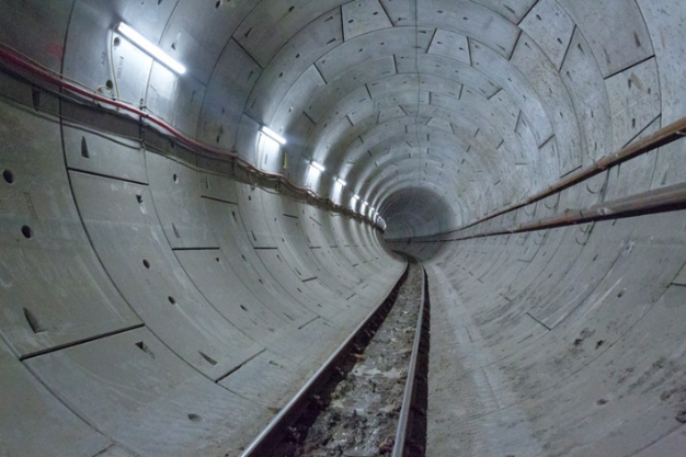
Figure 2 – Crossrail precast concrete segmental running tunnel
Sprayed Concrete Linings (SCL)
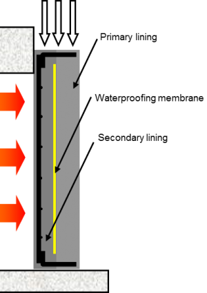
The sprayed concrete lined tunnels on the project are built up with multiple layers of sprayed concrete, waterproof membrane and fire protection as shown in schematic form in figure 3, with some layers sprayed in 2 passes depending upon tunnel size and lining thickness, for example P1 and P2 for the primary lining as indicated in figure 3. The majority of the SCL tunnels were generally close to circular with finished internal diameters ranging from under 5m up to about 10m. The crossover and bifurcation caverns were closer to an elliptical shape with an excavated diameter across the major axis (horizontal) of over 17 m and across the minor axis (vertical) of about 14 m, but were built up with a similar layer arrangement to that shown in the figure 3.The different layers were generally steel fibre reinforced with the exception of the regulating layer, which had a smaller aggregate and no fibres, and the fire protection layer, which had no steel fibres but included monofilament polypropylene fibres as discussed later in this paper. At some locations, for example close to junctions with crosspassages and in the larger and flatter crossover caverns, local reinforcement was introduced in thickening layers inside the primary lining, or in the secondary lining to resist the higher bending stresses. On Crossrail, the primary lining forms part of the load carrying permanent works.
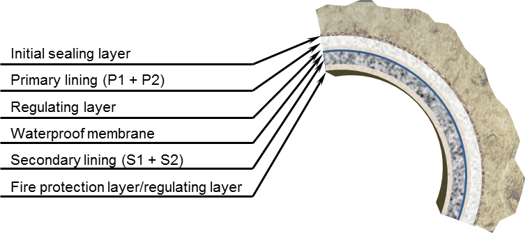
Figure 3 – Schematic of SCL layer build up
Tunnel structures under fire
Project performance requirements
The requirements for the tunnel structures included the need to follow the European Technical Specification for Interoperability – Safety in Railway Tunnels3 that was current at the time of scheme development and project design. This Specification mandates the use of the RABT-ZTV (EUREKA) fire curve (see figure 4) for structural design, and includes a requirement for the safety of people in the tunnels while evacuation is undertaken, but makes no specific provision for the longer term stand-up time and ground support. The Crossrail project made the decision that the hazards associated with the risk of loss of ground support in this urban environment during or after the design fire scenario were too great to contemplate, and specified a requirement that the ground support would be maintained, albeit with a reduced factor of safety, even after the design fire event. This did not preclude the acceptance of damage to the linings requiring some repair at a later date, and the limits listed in table 2 summarise the designer’s specified requirements.
The Technical Specification for Interoperability is based upon hydrocarbon type fires and is applicable only to structures directly surrounding the train pathway. Other underground structures such as crosspassages protected by a fire door and escalator tunnels did not fall within this definition and have generally only been required to meet local Building Regulation fire loads based upon a cellulose type fire. There were some local exceptions to this such as ventilation adits as these had the potential to be exposed to fires similar to the main running and platform tunnels. The tests and results discussed in this paper are for the EUREKA fire curve exposure only.
Table 2 – Summary of project performance requirements of test samples
Precast segmental linings Sprayed and cast insitu concrete linings Spalling limit 25 mm Fire protection layer + 25 mm Temperature limits 4500C at level of reinforcement.
Suppliers declared acceptable limit at level of waterproof membrane.
Residual strength after fire 70% of design 28 day strength 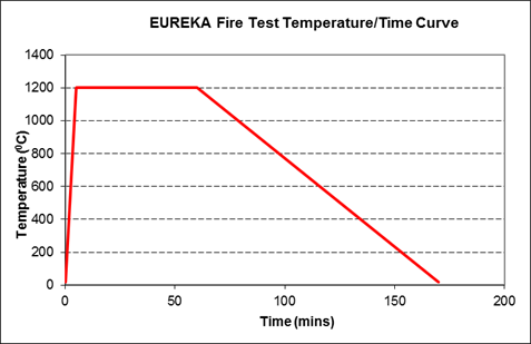
Figure 4 – Eureka curve time-temperature profile
Protection materials adopted
Previous tests and projects had demonstrated that polypropylene fibres within the concrete mix can significantly enhance the performance of the material under fire conditions1,2 by limiting concrete spalling. The use of these fibres is also recommended within Eurocode 24. Variations of approach to the use of this material were taken depending upon the construction methods adopted, and these approaches are summarised below:
- Segmental linings – polypropylene fibres incorporated throughout the full segment thickness for both steel fibre reinforced segments and segments with local traditional reinforcement.
- Sprayed Concrete linings – polypropylene fibres incorporated into a final layer of sprayed material. Minimum thickness specified by the designer to be 50mm.
- Cast insitu linings – polypropylene fibres incorporated throughout the full lining thickness for both steel fibre reinforced sections and areas with traditional reinforcement (for example close to openings).
In other parts of the project works that were required to be designed for similar fire conditions (for example piled walls, diaphragm walls and insitu concrete slabs, which are not covered in this paper), other proprietary products including both sprayed and protection board products were also used.
Testing regimes
The final configurations and material selections for the PCL and SCL structures were required to be verified under large scale fire testing to the specified EUREKA curve, and all tests were to be undertaken under compressive loads representative of the loads on the structures in the Works. The stresses applied to the test piece allowed for the worst case design load stresses, plus the effects of stress increase due to lining expansion in the ground under elevated temperature conditions.
For the precast segmental lining tests, curved members representative of the tunnel segments which were 300 mm thick were used rather than flat panels. The test set-up was as shown in figure 5, and the stresses in the lining during the test were controlled by relaxation of the rams to compensate for the test segment expansion during the fire test. Deformation of the segments was also monitored during the test but this was found to be minimal and had no significant impact on the performance of the concrete under fire test conditions.

Figure 5 – Precast segmental lining test arrangement
For the SCL tests, initially small scale tests were undertaken on unloaded cylinder samples to compare the performance of different fibre dosages, concrete mixes and, if required, fibres from different suppliers. These were followed by large scale sprayed flat panel tests on samples with a total thickness of approximately 500 mm, with the test undertaken under compressive loads as shown in the arrangement in figure 6. Most tests had a vertical panel arrangement rather than horizontal to suit the furnace equipment available, although horizontal test set-ups were also acceptable.
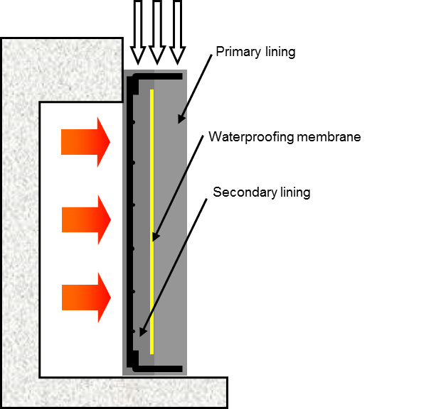
Figure 6 – Test panel arrangement for representative SCL linings.
During the tests instrumentation and monitoring were included to measure the following: loads (concrete stress); temperature in the concrete at various depths using thermocouples; and spalling depths immediately after the test and after a cooling period for the samples.
Test results and compliant materials for PCL
Table 3 below outlines the mix designs for the successful test segment samples and table 4 contains summary details for the spalling depths measured. It should be noted that the results of fire tests are very specific to the mix design and particular fibres and only provide guidance for possible successful combinations on future projects unless very similar mixes and material sources are used. The stress regime within the test samples can also influence performance and this should also be taken into account.
Table 3 – General PCL concrete mix details.
Material Contract C300 Contract C305 Contract C310 CEM1 – Portland Cement (kg/m3) 287 337 258 PFA/GGBS (kg/m3) 123 113 172 20mm Limestone Aggregate (kg/m3) 643 723 263 10mm Limestone Aggregate (kg/m3) 684 361 706 Sand (kg/m3) 509 765 778 Steel fibre dosage (kg/m3) 35 30 30 Polypropylene fibre dosage (kg/m3) 1.25
(Propex 32 micron)
2.0
(Propex 32 micron)
1.5
(Baumhueter Eurofibre HPR)
w/c ratio <0.35 0.32 0.33 Table 4 – Spalling depths from successful fire tests
Measured spalling depths C300 C305 C310 Average spalling depth (mm) 16 8 3 Maximum spalling depth 23 13 14 Figure 7 below shows smoothed lines for the maximum temperatures measured with depth into the concrete (referenced to the face at the start of the test) from all test results. The maximum values were measured on one of the C300 tests. Temperatures were measured using 2 thermocouples in each layer being measured, spaced at 500 mm along the center-line of the segment. Average values from all of the successful tests at the higher temperature points along the curves shown in figure 7 at each layer were about 70-80% of the maximum values shown.
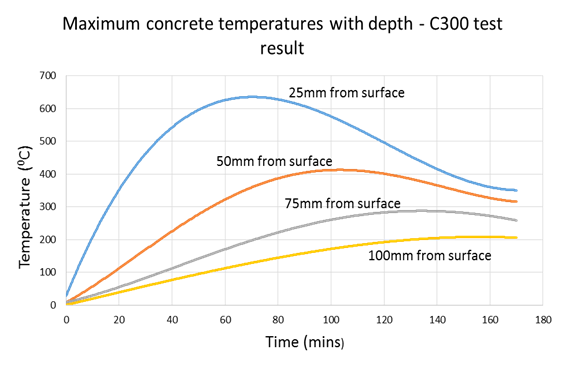
Figure 7 – PCL “Smoothed” maximum temperature profiles with depth for EUREKA fire test
Test results and compliant materials for SCL
The SCL had a higher variability in mix designs than the PCL, with more variance in the type and number of different aggregates used and the nature and type of the admixtures. Table 5 below summarises principle quantities only for the main mix designs, with the final fire protection layer being of a similar mix but with polypropylene fibres in the mix and no steel fibres.
Table 5 – General SCL concrete mix details.
Material Contract C305 Contract C410 & C435 Contract C510 Cement (kg/m3) 399 455 400 Microsilica (kg/m3) 52 50 52 Large aggregate – Limestone (kg/m3) 435 629 505 Small aggregate – Limestone (kg/m3) 435 – 590 Sand (kg/m3) 870 1168 580 Steel fibre dosage (kg/m3) – not in fire protection layer 35 35 35 Polypropylene fibre dosage (kg/m3)
Fire protection layer only.
1.0
(Propex 32 micron)
1.0
(Adfil Ignis)
2.0
(Propex 32 micron)
w/c ratio 0.4 0.36 0.43 It was also necessary for the SCL contracts to test two panel types – one with the secondary lining consisting of steel fibre reinforced concrete, and another with a secondary lining consisting of plain concrete (no steel fibres) but with a representative quantity of traditional reinforcing steel to simulate conditions at tunnel junctions where higher bending moments are present and they require additional flexural strength.
Results from successful tests of temperature against depth within the SCL section are summarised in figure 8 where the maximum results from the tests are plotted for both the steel fibre reinforced sections and traditionally reinforced sections, all with the polypropylene fibre fire protection layer sprayed at a minimum of 50 mm. All distances are referenced to the concrete face at the start of the test.

Figure 8 – SCL “Smoothed” maximum temperatures with depth for EUREKA fire test
Additional tests were undertaken by various contracts during the project to demonstrate alternative arrangements for the linings and fire protection to suit particular construction circumstances. The following summarises the tests that met the specification criteria and which were accepted as solutions for the permanent works.
- C410 – 40 mm layer of polypropylene fire protection layer sprayed over steel fibre reinforced secondary lining (note that 40 mm fire protection over reinforced concrete failed the specification criteria on 1 out of 3 tests and was not accepted)
- C510 – Light stainless steel mesh and anchors within the fire protection layer at 50mm cover to assist with profile control
- C510 – secondary lining sprayed in 2 main layers (nominally 150 mm each) with polypropylene fibres and steel fibres in the final layer, ie without a separate fire protection layer but with local protection against snagging on steel fibres at the surface being required in some areas.
Generally there was more spalling and some delamination of the fire protection layer witnessed during the SCL test compared to the PCL tests, but the loss of the protection layer when sprayed as a final layer was acceptable for the design as long as spalling of the remainder of the secondary lining was less than 25 mm. The majority of tests saw no spalling of the secondary lining although some spalling of up to 20 mm was detected in a few panels. Figures 9a and 9b show typical results of damage to the fire protection layer of the test panels, the majority of which occurred during the cooling phase after the main test rather than being visible immediately after removing the sample from the furnace.
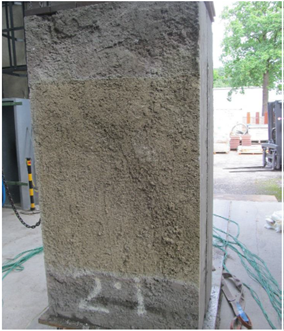
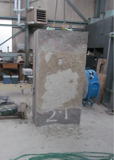
Figure 9a – Test panel immediately after test
Figure 9b – Same panel after cooling
Lessons learnt from spraying fire protection layers
A number of lessons can be taken from the Crossrail experience during the construction of the works of spraying relatively thin layers of fire protection. The main considerations for future projects would include the following:
- Profile control and space proofing for the final layer needs consideration as tolerances are far larger than can be achieved with cast insitu linings. Sufficient space needs to be allowed for tolerances affecting every sprayed layer to achieve the minimum thicknesses and allow sufficient space for subsequent layers, recognising that far greater construction thicknesses are also possible. Even allowing for tolerances of +/-30 mm on the fire protection layer have proved to be challenging, particularly at junctions.
- Surface preparation is critical to achieve good bond between the layers and a process using continuous cleaning with high pressure systems and only spraying small areas is required.
- Bond below axis has proved to be more difficult to achieve. This is thought to be at least partly related to the surface preparation and the constant need to meticulously remove both dust and wash down water from the spray area.
Tunnel structures under water pressure
Project performance requirements
The project general watertightness performance requirements are summarised below.
- For tunnels containing track, the area above axis to be free from all leakage seepage and damp patches and comply with the requirements of BS 81025 Table 2; grade 3 (No water penetration acceptable; Ventilation, dehumidification or air conditioning necessary, appropriate to the intended use).
- For tunnels containing track, leakage from the area below axis to be limited to damp patches and minor weeping of joints. The average level of water ingress in any drainage section to be less than 0.12 litres/day/m2, except that within any 10 m length, ingress of 0.24 litres/day/m2 would be permitted from any separate square metre.
- Tunnels and shaft areas accessible to the public to be free from all leakage seepage and damp patches to provide a dry environment.
- Tunnels and shafts not accessible to the public to be limited to damp patches and minor weeping at joints. Water ingress in any individual location to be limited to less than 1litre/day/m2 and the average shall not exceed 0.1 litres/day/m2.
Materials adopted
To achieve these standards the segmental lining design required the use of gaskets on every segment of every ring. Composite EPDM/hydrophilic gaskets were envisaged to be used across the project at the design stage, to make use of both the mechanical pressure between gaskets to form a seal, and an expanding component (hydrophilic) when in contact with water. A concession was granted where the tunnels passed through zones of relatively impermeable clay to delete the requirement for the hydrophilic portion of the gasket and to rely on the purely mechanical EPDM element.
For tunnels with sprayed concrete secondary linings, sprayed waterproof membranes were used, and where cast insitu secondary linings were to be used the contractor had the choice of either using a sprayed membrane or a more typical arrangement of geotextile fleece and sheet membrane. Sheet membranes could be used locally, for example where the invert only was to be cast (figure 10a) or as a full seal on its own where a full tunnel shutter was to be used to cast the secondary lining (figure10b). There were also some local issues and exceptions to be taken into account, for example at escalator barrels, where sprayed rather than sheet membranes were used with cast insitu secondary linings to prevent connections between aquifers at different strata levels. Sheet membranes are a well-established and tried and tested method of waterproofing tunnels and this paper will therefore only deal with sprayed membranes in the following sections.
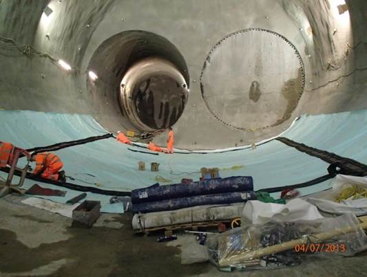
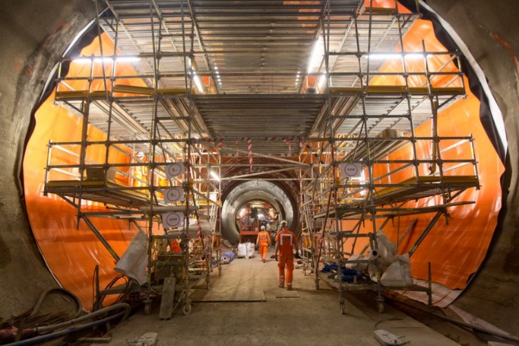
Figures 10a) and 10b) – Sheet membrane installation Testing regimes
All of the waterproofing materials were subjected to a wide range of material performance and durability testing, but this section deals only with aspects related to meeting the watertightness performance requirements of the project.
The gaskets for the segmental linings were tested for water pressure resistance under laboratory conditions and replicated maximum lipping between segments as well as maximum potential joint “gaps” due to the various tolerances for manufacture, construction and ring distortion under load. Taking these elements into account led to the gaskets being tested for a water pressure up to 8 bar, which was 2 times the expected working pressure.
Extensive use of sprayed waterproofing membranes had not been deployed on the scale required by the Crossrail project in the UK before. There was limited experience available from Europe and a road tunnel project in the South of England, and small scale use on other underground metro projects in London, but Crossrail was to use the material in much greater quantities and in areas with more difficult ground conditions. In addition to a number of site trials, physical testing of the sprayed membrane included the following:
- Membrane bond to substrate (greater than 0.5 MPa required)
- Permeability (zero penetration of water at 10 bar after 28 days)
- Crack bridging
- Flammability (temporary condition requirement)
Test results and compliant materials for the segmental linings
All of the segmental lining contracts opted for a gasket supplied by Datwyler, which had a profile that fitted within the same groove size whether the pure EPDM gasket was used, or the composite EPDM/hydrophilic type was installed. Test results showed that gaps of up to 7mm could be tolerated after 48 hours of the hydrophilic material expansion at a test pressure of 8 bar and an offset of 10 mm, which exceeded the project requirements. Similar results were achieved for the gasket with no hydrophilic component, although the gasket section height was slightly greater and the forces required to fully compress the gasket slightly higher than the lower profiled gasket with the added hydrophilic strip.
Test results and compliant materials for the sprayed concrete linings
At the time material selection for the sprayed membranes was occurring, there were essentially only 3 manufacturers supplying sprayed waterproofing materials that were considered to have the ability to meet the specification requirements. It is recognised that this is an area where manufacturers are, relatively speaking, rapidly changing materials and developing solutions to suit new demands and address observations that may be made as more experience is gained. It is not the purpose of this paper to make comparisons between the materials available at the time, or the new materials that are now making their way onto the market. At the time that testing was being undertaken on sprayed membrane materials, all available sprayed membrane materials examined met the performance requirements specified by the project.
The bullet points below include some observations made during the Crossrail works that, should similar conditions be present on a project considering sprayed waterproof membranes, may need to be addressed with the individual suppliers. Not all observations apply to all sprayed membrane material types and are provided only to highlight areas that may need to be considered on future projects:
- Blistering behind the membrane was locally an issue at some sites even where the substrate the membrane was sprayed onto looked dry. This was due to moisture in the substrate evaporating while exposed and appearing dry prior to sealing with a membrane. Re-sealing using crack injection techniques and local re-spraying of the membrane was required to rectify this issue.
- Preparation of the substrate is critical to the success of the installation particularly if reasonably high levels of bond are required. More objective methods of measuring acceptable surface preparation (for example roughness, undulation, cleanliness) would benefit future projects.
- Specifications should require demonstration of bond between the membrane and the lining sprayed directly onto the membrane (usually the secondary lining) as well as the bond between the membrane and the substrate. This is particularly important if any form of composite action is being considered in the design where issues such as bond, shear and elastic modulus impact upon the design.
- Designs should consider that some bond may be present even if the design does not require it for structural action – this changes the distribution of stress between the lining layers and has the potential to make stresses in the secondary lining more onerous.
- Some membranes demonstrated a change in behaviour under longer term testing and under saturated conditions including a reduction in bond and a reduction in elastic modulus. This becomes particularly relevant for any design utilising a model of composite action between the lining layers, although this was not a requirement on Crossrail.
Conclusions
The Crossrail project has successfully developed tunnel lining structural and serviceability solutions to meet the conflicting demands required by fire resistant and water resistant structures. There are lessons to be learnt concerning the use of thin sprayed concrete layers and sprayed waterproof membranes and this paper has attempted to highlight the high level areas that should be examined in more detail for projects where similar solutions are being considered.
References
- Shuttleworth, “Fire Protection of Concrete Tunnel Linings” 3rd International Conference of Tunnel Fires and Escape From Tunnels, Washington DC, 9-11 October 2001
- Lennon and N. Clayton, “Fire tests on high grade concrete with polypropylene fibres” 5th International Symposium on the Utilisation of High Strength/High Performance Concrete, Savdejord, Norway, June 1999
- Technical Specification for Interoperability – Safety in Railway Tunnels. No 2008/163/EG. (Note – this document now superseded by Commission Regulation (EU) No 1303/2014)
- BS EN 1992-1-2:2004. Eurocode 2: Design of Concrete Structures. Part 1-2: General Rules – Structural Fire Design. British Standards / European Committee for Standardisation.
- BS 8102:2009. Code of practice for protection of below ground structures against water from the ground. BSI Standards Publication.
-
Authors

Mike King BSc CEng MICE - Crossrail Ltd
Technical and Compliance Director – Tunnels, CH2M