Fisher Street Crossover – Construction of the Secondary Lining
Document
type: Technical Paper
Author:
Claudio Dias, Filipe Mello, John Wallis, Pawel Czajkowski, Yaser Maqsud, ICE Publishing
Publication
Date: 30/09/2017
-
Read the full document
Introduction
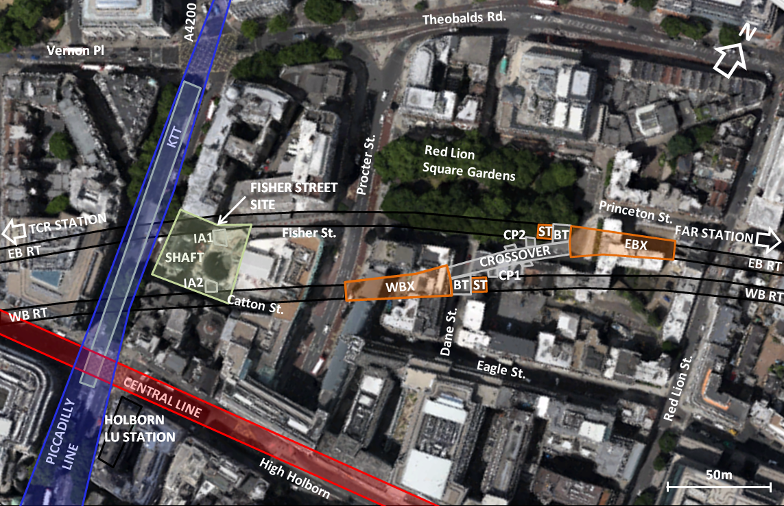
The location of Fisher Street site in a busy and lively area of Central London meant it had some constraints which limited the type and extent of certain work activities (location shown in Fig 1). The site is bounded by Fisher Street (to its north), Southampton Row (west), Catton Street (south) and by a UK Power Networks (UKPN) building to its east. Fisher Street was closed to its western end to accommodate the BFK worksite. Catton Street was closed for non-Crossrail construction works. Access for lorries and deliveries was restricted to the eastern entrance through Fisher Street. Besides the physical barriers, some construction activities that generate ground borne noise and vibration were also subjected to time restrictions due to the local residents in the vicinity.
Construction began after the running tunnels were excavated by two EPBMs and included the realisation of the following structures:
- An access / intervention shaft;
- Two intervention adits (IA1 and IA2) to connect the shaft to the running tunnels;
- Two tunnel enlargements (caverns) – one in the eastbound (EBX) and other in the westbound (WBX) route;
- A crossover tunnel connecting the two caverns;
- Two cross-passages – each connecting to the running tunnel and crossover tunnel;
- Two niches in the crossover – storage areas.
The intervention or access shaft is located behind a Grade-II listed building, at 8-10 Southampton Row, where oversite development will follow once the main Crossrail works are completed.

Figure 1 – Location of Fisher Street site
Underground Works
The tunnelling works undertaken at Fisher Street involved the use of different liners:
- The intervention shaft, 30m deep by 15m diameter, constructed using 10m deep secant piles followed by excavation and primary Sprayed Concrete Lining (SCL) to the base level and completing the shaft with sheet waterproofing and cast-in-situ secondary lining works;
- Crossover tunnel, 45m2 cross section by 59m long, constructed using SCL for the primary lining and cast-in-situ concrete, for the secondary lining;
- Eastbound and westbound tunnel enlargements, cross sections vary between 60 and 140m2 by 56m long, constructed using sprayed concrete lining for both, primary and secondary lining.
The simplified local geology consisted of Made Ground and River Terrace Deposits, from the surface level to 8m deep, followed by an 18m stratum of London Clay, 11m of Lambeth Group, 11m of Thanet Sand Formation, and Chalk Group at the bottom. The bottoms of the caverns were excavated within the Lambeth Group, with the tunnel crown in the London Clay with a proportion of 25 per cent and 75 per cent respectively.
Design and Specifications
Traditional methods of building tunnels in soft ground typically demanded the construction of a double lining structure, referred to as the primary and the secondary lining (with sheet waterproof membrane in between), of which Fisher Street Intervention Shaft is an example. With modern improvements in sprayed waterproofing technology, and understanding of the lining behaviour, it is acceptable to consider the primary lining as part of permanent works. At Fisher Street this method was used with two variations: a sprayed secondary lining, for the east and westbound tunnel enlargements; and a cast in situ secondary lining for the headwalls of the tunnel enlargements, crossover and binocular tunnels.
SCL design contract C121 was awarded to Mott MacDonald in May 2009. The SCL design included the use of steel fibre reinforced (SFR) concrete, mainly for the primary lining, a regulating layer and a spray applied waterproofing system followed by sprayed or cast in situ secondary lining. In terms of durability, the project materials and workmanship specifications required a tunnel complying with an expected service design life of 120 years.
The contractor was required to carry out trials to demonstrate compatibility with the intended construction methods and suitability of concrete mixes. A few examples of these are: spray trials to investigate the reinforcement encapsulation, fire tests to examine the competency of the fireproof mix and site trials to demonstrate confidence on the contact grouting system.
To achieve the required fire resistance (Eureka curve, 170 minutes), a “finishing layer” with a minimum 50mm thickness and polypropylene fibres at a dosage rate of 1kg/m³ was required. This layer served two main objectives; to ensure a steel fibre free finish of the SCL and provide a passive fire protection to the structure.
Construction Sequence
Logistics were the major challenge during the construction of the Fisher Street caverns and crossover tunnels, working in parallel to First Stage Concrete works from Tottenham Court Road to Farringdon. The difficulty of the interface of these activities with the removal of backup gantries of two TBMs from Farringdon, via the small intervention adits from running tunnels to the Fisher Street shaft was only matched by the complex geometry of the tunnels.
Achieving progress despite the on-site constraints and providing an uninterrupted supply of concrete into the tunnels was another big challenge. This was overcome by providing two vertical boreholes constructed from the KTT, between the Crossrail tunnels and KTT level, that allowed for direct discharge of concrete into the tunnels which was then transported via concrete mixer trucks to the working faces. This allowed the removal of the delivery of thousands of cubic meters of ready mix concrete (batched off-site and delivered in 7m3 concrete trucks) from the small footprint of the Fisher Street site and allowed good progress with the long continuous concrete pours.
Figure 2 presents a cavern cross section with its main features and construction sequence for a section of approx. 60m2 and 350mm secondary lining design thickness. Regarding Figure 3, this presents similar information for a typical crossover section of approx. 45m2 and 250mm secondary lining design thickness. Table 1 presents the simplified construction sequence which will be discussed in the following numbered paragraphs.
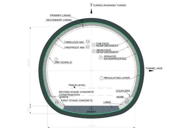
Figure 2 –Tunnel Enlargement Cross Section
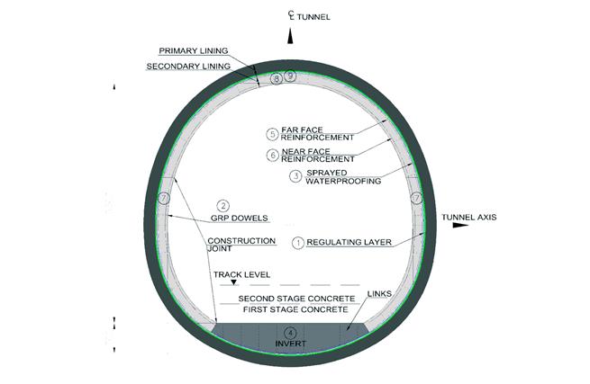
Figure 3 – Crossover Cross Section
Table 1 – Secondary Lining Construction Sequence
Construction Stages Sprayed Secondary Lining Cast in Situ Secondary Lining 1 Spray Regulating Layer over PL 2 Install GRP dowels 3 Spray Waterproofing Membrane 4 Cast Invert 4A Cast Kerbs N/A 5 Install Far Face Reinforcement 5A Spray S1 Layer N/A 6 Install Near Face Reinforcement 6A Spray S2 Layer N/A 7 N/A Cast Walls 8 N/A Cast Crown 9 N/A Contact Grouting 1) A fibreless mix was sprayed for the regulating layer over the primary lining (PL). This was done to prepare a surface free of any irregularities and ready to receive sprayed waterproofing membrane application. Surface roughness was checked through a comb test, in which no troughs greater than 10mm were desired, while ensuring no steel fibre protrusion from the PL.
2) Installation of Glass-Reinforced Polymer (GRP) dowels for supporting the secondary lining (SL) reinforcement. The installation of dowels, prior to spraying the waterproofing, saved time and material as it reduced the potential need to repair the waterproofing membrane around the dowels (if done in a later stage).
3) After the application of the waterproofing, the area was protected and allowed to cure sufficiently to achieve Shore A hardness of 50 for sprayed SL and 30 for cast in situ concrete, to avoid damage to the waterproofing. Although, a detailed study on waterproof material quantities has not taken place it was clearly noticed that if care was not exercised during the waterproofing application, an extra coat(s) could be required on top of what would normally be expected. An acceptable finished surface should be free of any defects (pin holes, etc) and in an optimal range of between 4 and 10mm.
4) For the casting works, special attention was given to waterproofing overlap areas which would require remedial works if damaged. Construction joints were prepared painting the stop ends with a concrete retarder and jet-washed to achieve a “green cut”. The use of crack inducers to work as contraction joints allowed time gains in erecting the formwork.
4A) The greater bending moments in the kerbs area resulted in a higher density of reinforcement in these regions. One of the challenges here was to reduce the risk of rebound encapsulation at the radial joint. As a field change design option the joint was still kept radial but with a step, higher at the back, allowing the rebound to fall in front of the spraying.
5) Special care was taken so the reinforcement installation did not damage the waterproofing membrane. If damage occurred or leaks were injected the area needed to be repaired by hand painting the waterproofing membrane and ensuring a 300mm overlap with the undamaged waterproofing membrane. The maximum size of the rebar was limited to 20mm to minimise the risk of poor encapsulation.
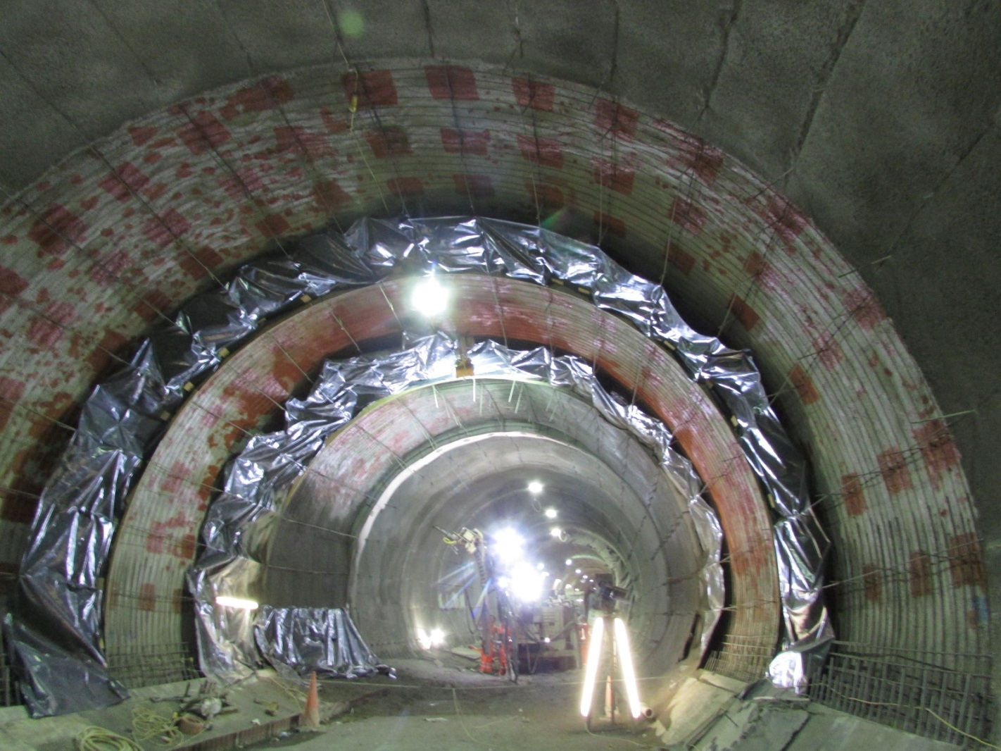
5A) As shown in Figure 4 the maximum stretch of spraying activity dictated the bay lengths and was dependant on the type of plant, exclusion zones, cross-section of the cavern and the type of joints to be achieved. The sprayed concrete operation followed smooth back and forth oscillating nozzle movements from the lower axis level towards the crown in a steady uninterrupted flow. The lining was built up by making several passes (maximum 100mm) of the nozzle over the working area. The thickness was controlled using the laser total station systems (through TMS Office from Amberg Technologies) and lacer bars to guide the sprayers. The use of stop ends showed good concrete compaction. The accelerator dosage: 5-6 per cent in the shoulders and 6-8 per cent in the crown. To suit the contractor’s method of construction, an additional hydrophilic strip was required to be installed on the longitudinal (cast-shotcrete) and circumferential (shotcrete-shotcrete) construction joints of the adjacent bays in EBX and WBX to ensure water tightness at the joints.
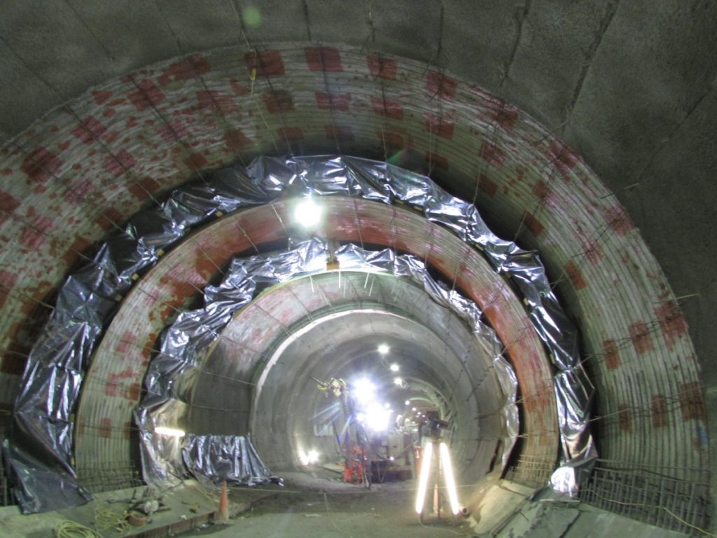
Figure 4 – Spraying bay S1 in EBX
6) For near face reinforcement, the use of couplers for kicker bars, at the kerbs, allowed the easy installation of reinforcement after spraying S1. This reduced the risk of shadowing in the S2 layer by avoiding the need to spray the S1 layer through two layers of reinforcement.
6A) The second layer – S2, has the requirements for a minimum 50mm lining of polypropylene fibres, and a design cover of 60mm. The requirement to spray a separate fireproofing layer was omitted with a value engineering proposal to incorporate a fireproof mix within the S2 layer. The 350mm of SL layer in WBX and EBX was then made up of first layer approx. 230mm of non-fibre reinforcement (has FF reinforcement) and a second layer S2 approx. 120mm with polypropylene fibres in the concrete mix. This option reduced the risk of delamination issues between S1 and S2, since both layers present an adequate thickness and encapsulate one of the reinforcement faces.
7) A self-compacting concrete (SCC) mix (C32/40) with GGBS and polypropylene fibres was developed for casting the walls and crown in the crossover, this mix had to be developed at short notice due to a nationwide shortage of pulverised fly ash (PFA) at the time of the works. The mix has two main advantages: it replaced the use of PFA with ground granulated blast furnace slag (GGBS) – reducing the project programme risk with any potential delays in PFA supply. Secondly, improvement in quality of the concrete finish – the use of SSC mix reduces the risk of segregation and poorly compacted concrete. It worked out to be a good solution for areas with heavy or complex arrangement of reinforcement.
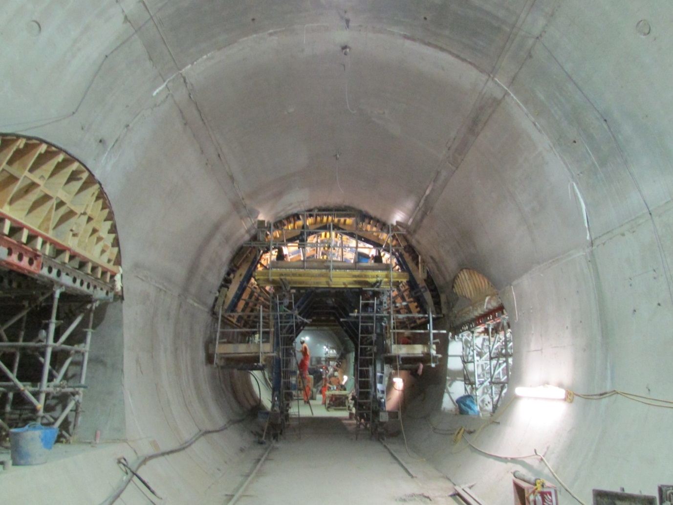
8) The separation of pours into two stages, wall and crown, was required to allow more flexibility to the works, as the crossover was necessary as access to the First Stage Concrete team working in both running tunnels at the time of the works. This changed the original design plan to spray the crossover SL. The crown was cast using a Doka travelling formwork, assembled on site and pulled from EBX cavern westwards towards WBX with chain blocks using channel rails, as shown in Figure 5.

Figure 5 – Travelling shutter casting the crossover crown
9) Any possible voids in the crown were contact grouted using a pumpable grout of 0.6 water/cement ratio with three per cent plasticiser, through pipes set in the concrete for this purpose along the highest areas of the tunnel. It was important to test the mix and the grout tubes at their maximum length prior to use. This was achieved through a full scale test in a slab built only for this purpose. The tubes were adequately fixed, to the reinforcement, to the highest areas to avoid displacement during casting works.
The secondary lining works related to the crossover tunnel and the western tunnel enlargement at Fisher Street took place from the first week of March to the last week of October 2015, a total of 35 weeks of the programme. Based on the shift reports and the design volumes for the lining, a construction rate for both SCL and cast-in-situ linings has been estimated. The rates quoted are based upon a 24-hour, seven-day working pattern and 100 per cent utilisation. There were no distinct differences in general delays and breakdowns noted. The relative percentage of time spent in each construction activity, per cycle, has been derived and presented in Figure 6. The data shows that the casting of the walls took almost the same amount of time as the casting of the crown. On the other hand the study demonstrates that spraying S2 took 30 per cent less time than spraying S1, since S2 is thinner than S1.
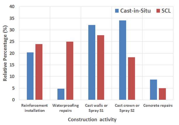
Figure 6 – Relative percentage of time per construction activity
It should be noted that this is not a detailed study, since it relies mainly on shift reports and design concrete volumes, and it did not consider a number of variables that affect the production process. Nevertheless, an average production rate for the cast-in-situ lining at junctions (crossover tunnel) of 2.8 m3/day and of 8.5 m3/day for the SCL (western tunnel enlargement) would be a fair comparison.
Conclusions
This paper presented the construction of a secondary lining at Fisher Street site, highlighting the main challenges of the project and the solutions developed by the engineering team. The project requirements and constraints discussed here are site specific, however, lessons learnt and good practices adopted can be taken forward to similar tunnelling projects with reasonable engineering skill and care.
Acknowledgements
The authors would like to thank to all parties involved in the works at Fisher Street Crossover, particularly to BFK, CH2M, Crossrail and Mott MacDonald.
-
Authors

Claudio Dias - CH2M, Crossrail Ltd
Claudio was seconded to Crossrail as a Field Engineer at Fisher Street site where he supervised the construction of the crossover’s secondary lining. He has an MSc in geotechnics and is a chartered European Engineer. Claudio started his career in Brazil, working on tenders and detailed designs of several metro systems in South America. In 2014, he joined CH2M in London, where he has been involved in major infrastructure projects, such as Tottenham Court Road Station Upgrade, Crossrail, Los Angeles Metro and Hinkley Point C. He is also actively involved in research, having published a number of papers in international conferences and journals.

Filipe Mello - BAM Ferrovial Kier
Tunnel Agent for SCL works
John Wallis - Mott MacDonald
Senior Resident Engineer
Pawel Czajkowski - CH2M
Crossrail Site Manager
Yaser Maqsud - CH2M
Crossrail Field Engineer