Fixed Fire-Fighting Systems
Document
type: Technical Paper
Author:
Gerry Mullan EngTech MIFireE, ICE Publishing
Publication
Date: 30/09/2017
-
Read the full document
Introduction
Fixed Fire-Fighting Systems are installed in buildings within firefighting shafts so that the fire service may connect hoses for water to fight fires inside the building. Rising fire mains serve floors above ground, or upwards from the level at which the fire service gain access. Falling mains serve levels below fire service vehicle access level.
Fixed Fire-Fighting Systems are classified as installed equipment and while not responding automatically to a fire, are available at strategic points for use by suitably trained occupants or the fire and rescue service. These systems convey the water to hose points without the need for laborious laying-out of hoses over large heights and distances.
Fire mains may be of the ‘dry’ type (Fig 1) which are normally empty and are supplied through hose from a fire service pumping appliance. Alternately they may be of the ‘wet’ type (Fig 2) where they are kept full of water and supplied from tanks and pumps in the building. There should be a facility to allow a wet system to be replenished from a pumping appliance in an emergency.
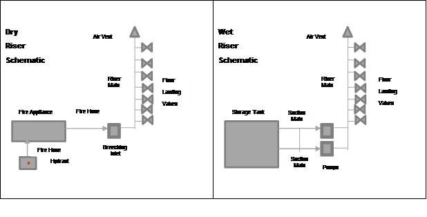
Figure 1 – Dry Riser Figure 2 – Wet Riser
The question is; what type of system would the Charged Dry Falling Main come under and which components would be suitable.
At Crossrail, we decided to adapt the Dry Riser (Dry Faller) system due to the environment and various constraints, which added the following to the design;
Having a permanently charged fire main became a necessity due to the volume fill times required for such a large system. To calculate this, the following simple equation provides the velocity:

Where
v = velocity (m/s)
q = volume flow (m3/s)
d = pipe inside diameter (m)If we use Figure 3 as an example, we can calculate the fill time from the Breeching Inlet to the most remote landing valve (opposite end of the platform to the selected Breeching Inlet).
The previously mentioned velocity equation confirms that 150mm pipe flowing at 25 litres/second provides a figure of 1.41 metres/second.
Using this figure and assuming 30 metres falling main, 240 metres horizontal main and a 25% fitting allowance, we can provide a fill time;
30 + 240 + 25% = 337.5 metres length
Fill time equates to length/velocity, which in turn would provide the result;
337.5/1.41 = 240 seconds or 4 minutes
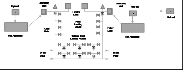
Figure 3 – Typical Crossrail Station Charged Dry Falling Main
With the air pre-vented and forces reduced in the system due to the pre-filled arrangement, the fill times would shorten dramatically.
The Crossrail Fire Main system has been divided into seventeen sectors and an example is shown in (Fig 4). The average depth between the lowest and highest point across the sectors is 26.5 metres.
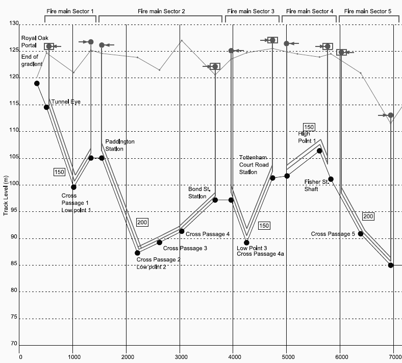
Figure 4 – Sector drawing showing west section
Large diameter pipe (200mm) has been specified in tunnel locations due to extensive distances and less restriction in flow and friction.
As there are a minimum of two Breeching Inlets on each system, co-ordination between the attending crews would be essential to confirm which inlet is used to pressurise the system. Only one inlet is required to pressurise the system.
Figure 5 – Crossrail configuration
Legislation
What’s in the British Standards
The two systems are covered in the current British Standard BS 9990 and are described as follows;
- Dry fire main – water supply pipe installed in a building for fire-fighting purposes, fitted with inlet connections at fire service access level and landing valves at specified points, which is normally dry but is capable of being charged with water usually by pumping from fire and rescue service appliances (Fig 1).
- Wet fire main – water supply pipe installed in a building for fire-fighting purposes and permanently charged with water from a pressurized supply, and fitted with landing valves at specified points (Fig 2).
In general, the British Standard BS 9990 covers multi-storey buildings above ground by the means of a riser pipe and landing valves situated within the fire-fighting stair.
Underground Fire Safety
As the Crossrail network is similar in construction to the London Underground system, following the LU standard S1-082 Active fire protection systems and portable fire equipment, became a standard reference document.
Key requirements from the document are described below;
- Fire hydrants and fire main systems shall comply with the recommendations made in BS 9990, with the exceptions detailed in the following clauses of this Standard. Compliance must be achieved for all public areas of the station and such non-public areas that are agreed with the Fire Authority as being of sufficiently high fire risk.
- Fire main outlets (wet or dry) shall be provided near each end of each station platform. The outlets shall be located in a fire-fighting shaft where one is provided. Where no fire-fighting shaft is provided, twin outlets shall be provided on landing valves (each incorporating a twin outlet and a suitable pressure-reducing valve arrangement) on each platform, a maximum of 60m from each head wall or platform end (whichever is the furthest from the fire-fighting access to the platform) and no more than 60m apart. Other outlets must be provided to ensure all parts of the route fire-fighters would use to access these outlets is no more than 60m unobstructed distance from an outlet.
- BS 9990 recommends the installation of isolating valves spaced a maximum distance of 10m apart. This is not required – isolating valves shall be monitored or secured with padlocks and straps and shall be positioned at locations chosen so as to optimise the efficiency of maintenance and to maximise the availability of the hydrant system in case of component failure.
- Dry mains and charged dry mains are required to have a nominal diameter of at least 150mm and a 4-way breeching inlet.
- Where the calculated time to fill the main via the apparatus available to the fire brigade is greater than 2 minutes, the main must be designed to be a charged dry main, kept filled with water and must incorporate the facility to top-up the system via a dedicated header tank.
This has formed the basis of the Crossrail design and adopted the title; Charged Dry Falling Main. This system also reduces the volume of air and allows for continuous monitoring of leaks.
Approvals
Selecting the correct components for the Charged Dry Falling Main becomes the most important factor due to flows, friction losses, pipe runs, hazards, and remoteness from the Breeching Inlet (Water Supply) and linked from more than one location.
BS 5041 Parts 1 & 2 requires each valve to be marked with the following:
a) The letters “LP” (for low pressure valves) or “HP” (for high pressure valves) in a position which will be visible after the valve has been installed;
b) The nominal size;
c) The manufacturer’s name or trademark;
d) The number of this standard, i.e. BS 5041/2CE marking on a product is the manufacturer’s declaration that the product complies with the essential requirements of all the Directives that apply to it. It indicates to the appropriate bodies that the product may be legally offered for sale in this country.
The requirements for CE marking differ across all the Directives and may also vary for different products within a Directive (Pressure Equipment (PED) 97/23/EC).
Depending on the product, CE marking may be as simple as formulating a technical file, or as complex as having to submit your products to regular independent scrutiny.
Considerations
The equipment should be provided in accordance with best practice, taking account of the system in which it operates. All materials used in construction shall be of the quality and of the type most suitable for working under the conditions specified for the full service life of the system.
Location of Breeching inlet
Fire appliance access should be positioned within 50 metres from an entry to any premises on the site (and not closer than 6 metres). The hydrants should be not more than 150 metres apart, and should be immediately adjacent to hard standing facilities provided for fire service vehicle access.
Thrust
In order to properly size thrust supports or other devices to hold a pipe in place; the momentum equation is used to compute the necessary resistive force to hold the pipe stationary. This is also called thrust restraint design. Forces from a change in direction in the horizontal plane are caused by the fluid’s momentum and pressure. A change in direction in the pipe vertical plane and where the entrance to the change is above the exit (or vice-versa), then the weight of the liquid and pipe material within the bend will contribute to the force. Judging by the table below (Fig 6), a 150mm pipe with 10 bars would have a thrust of 35 kN at a standard bend.
Internal pressure thrust per bar
Pipe ID
(mm)
End thrust (kN) Radial thrust on bends (kN)
90° 45° 22½° 11¼° 50 0.38 0.53 0.29 0.15 0.07 75 0.72 1.02 0.55 0.28 0.15 100 1.17 1.66 0.90 0.46 0.24 125 1.76 2.49 1.35 0.69 0.35 150 2.47 3.50 1.89 0.96 0.49 175 3.29 4.66 2.52 1.29 0.65 200 4.24 5.99 3.24 1.66 0.84 Figure 6 – Typical pipe thrusts
The pipework and fittings used for water supplies for hydrant systems, and fire mains, should be correctly sized, taking account of hydraulic characteristics, such that the required pressure and flow requirements are delivered at the hydrant outlet.
Access
Requirements for access for firefighting to any premises are as identified in the Building Regulations Approved Document B and in BS 9999. This is also identified in Fire Brigade Fire Safety Guidance Note – GN29. They identify requirements for road width access, turning provisions and design loadings and identify access requirements to the perimeter of buildings. RSPG identifies intervention access requirements for underground tunnel networks including protected Intervention access (Firefighting shafts) and tunnel walkways.
Pipe Identification
Fire mains and associated equipment should be identified in accordance with BS 1710. The colours of the sign shall be as follows:
Background colour: red ~ Graphical symbol: white.
The safety colour red shall cover at least 50 % of the area of the signSuitability of equipment
Fixed Fire-Fighting systems should be designed so that, so far as is reasonably practicable, all equipment can be installed, maintained and renewed without affecting other systems.
Consideration to optimise planned inspection and maintenance during the railway’s operational hours and minimise the requirement for possessions and station closures.
To increase reliability and availability, the use of bespoke equipment should be avoided. All equipment of the same ‘type’ should be interchangeable.Pressure regulation
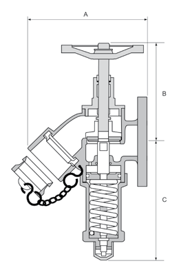
Pressure regulating landing valves should be fitted with a device which, when the outlet is restricted, limits the outlet pressure to a value not exceeding 7 bar. Where the means of pressure limitation is a pressure regulating mechanism, any means of adjustment shall be fitted with a locking/clamping device to maintain the initial setting.
The valve shall comply with all the requirements of BS 5041 Part 1 without alteration of the initial setting.Pressure Gauges
Means should be provided to enable confirmation of the available pressure in the Fire Mains for maintenance and fire-fighting purposes. Pressure gauges should be a glycerine filled type with a test configuration to verify the operation, as shown (Fig 7).
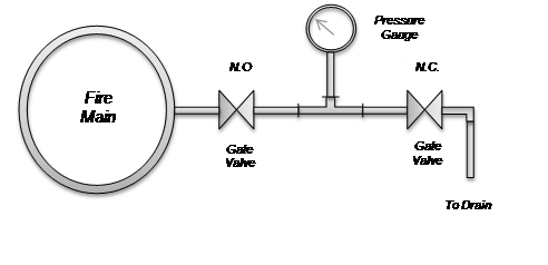
Figure 7 – Pressure Gauge arrangement
Drainage
Means should be provided to enable draining of pipework at the lowest points and where any trapped sections should exist. Drain Valves should discharge to a drain connection capable of handling the flow of the drain. This would also apply to flow testing with appropriate measures in place, i.e. using additional containers/tanks to temporary hold the volume and instigate slow release to drain.
Positioning
The system should be installed to be easily accessible for repairs and alterations.
The pipework should not be embedded in concrete floors or ceilings or where possible in concealed spaces that make inspection, repairs and modifications difficult.
When selecting the position of landing valves, account should be taken of: ease of access; exposure to fire from the accommodation if a door is open; obstruction of fire doors by the hose line; and the risk of unintentional discharge of water coming into contact with the lift doors or controls.
Materials
Valves
Landing valves, on the system should be of wheel operated pattern, with a BS 336 female instantaneous coupling outlet to take standard fire service pattern hose.
Landing, Isolation and Drain valves should be positioned so that hand wheels and outlets can be easily operated.
Butterfly type Isolation valves with grooved ends should be utilised, for use with a grooved pipe coupling system. The valves should also be designed for use on fire protection systems and have as a minimum LPCB certification of approval, LPS 1185. The valves shall be operated by a hand wheel, include a worm and wheel gearbox in a housing and the housing shall be waterproof with the facility for monitoring. The open/close status shall be indicated by a flag above the valve.
Valves are generally lockable using a leather strap and padlock.Breeching inlets shall comprise a four-way breeching inlet to BS 5041 with a 150mm diameter outlet connection to BS EN 1092 NP 16. As 200mm pipework was sized for the Tunnel mains, a 200mm x 150mm eccentric reducer would be required as close as possible to the Breeching Inlet. The inlet connections must be 65mm instantaneous male hose couplings to BS 336.
Air release valves should be suitable for use on fire protection systems and have a nominal size of 25mm.
Landing valves should comply with BS 5041, Part 1 for wet fire mains, and part 2 for dry mains, so in our system, we used Part 1 valves. Landing valves should be protected from vandalism; this may be by means of installing them in a cabinet designed in accordance with BS 5041: Part 4.
Custom designed cabinets, to suit station surface designs, may be required, and where these are used it is important that the functional requirements of the British Standard are maintained (especially operational clearances etc.) in the custom design. Cabinets on Station platforms should be large enough to hold equipment associated with a station platform fire point.
In our case, the Stations are served by the main at multiple levels below ground level; there will obviously be an undesirable variation in pressure. To overcome the variation in pressures the landing valves will need to be fitted with a pressure regulation system to ensure that excess pressures are not transmitted to the fire hose (Fig 8).
The function of a pressure reducing regulator is to precisely reduce a high upstream pressure of water from the Fire Appliance to a lower, stable pressure for the user’s application. Furthermore, the regulator will attempt to maintain and control the outlet pressure within limits as other conditions vary but the regulator will not control flow, only the delivery pressure
The reduced pressure can be adjusted via the adjusting cap; this design has several advantages over conventional adjusting screw designs. These include the fact that no threads are exposed, making it virtually impossible to damage them. It is also more robust and able to cope with accidental knocks. The valve is locked in position with a locking wire and seal. This not only prevents the adjusting cap from moving, maintaining a specific reduced pressure, but also provides a simple indication to whether the valve has been tampered with.
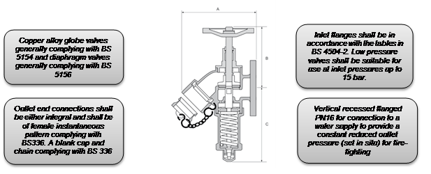
Figure 8 – Pressure Regulating Landing Valve
A regulator’s main purpose is to maintain a constant pressure on one side of the regulator even though there is a different pressure or fluctuating pressure on the other side. In the case of a pressure-reducing regulator, pressure is controlled downstream of the regulator.
A flow curve illustrates a regulator’s performance in terms of outlet pressure (Y axis) and flow rate (X axis). Flow is not controlled by the regulator. It is controlled downstream by a valve or flow meter. The curve shows how a regulator will respond as flow in the system changes (Fig 9).
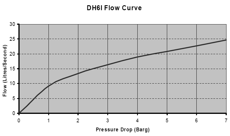
Figure 9 – Pressure Reducing Landing Valve Flow Curve
Pipe & Fittings
In general, the BS 9990 covers the requirements for this with the exception of threaded joints and connections on large bore pipework (>65mm), which are not permitted.
The pipework and fittings used for water supplies for hydrant systems, and fire mains, should be correctly sized, taking account of hydraulic characteristics, such that the required pressure and flow requirements are delivered at the hydrant outlet.
The pipe should be of heavy quality, wrought steel, galvanised for corrosion resistance, and a dual certified product in accordance with EN10255 and EN10217-2. In addition, the pipe should conform to the Products Regulation (CPR), Pressure Equipment Directive (PED) requirements, CE marked to CPR CAT 4 (water) for added confidence, where applicable.
Only mechanical couplings complying with LPS 1219 or equivalent should be used with a galvanised finish and should have appropriate electrical continuity as part of the integral design.
Grooved mechanical couplings are available with two distinct performance features: rigid and flexible couplings. Rigid mechanical couplings are designed to ‘fix’ the joint in its installed position, permitting no linear (Fig 10) or angular movement (Fig 11) at the joints. Flexible grooved mechanical couplings on the other hand are designed to allow controlled linear and angular movement at each joint that can accommodate pipeline deflection and piping thermal movement.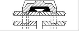
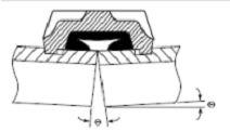
Figure 10 – linear movement (Top) Figure 11 – angular deflection (Bottom)
The design of the components enables grooved mechanical flexible couplings to allow for controlled movement in the pipe joint. Because the dimensions of the coupling key are narrower than the groove in the pipe, the coupling key has room to move in the pipe groove. Additionally, the width of the coupling housings allows for pipe-end separation. This leaves room for controlled linear and angular movement at the joint. The mechanical coupling remains a self-restrained joint, suitable for various environments (Fig 12) and the unique pressure-responsive design provides sealing even under deflection and pipe movement.
Standard Gaskets
Grade Temperature Range Compound Colour Code General Service Applications E
-40˚C to 110˚C EPDM Green Water, salts, alkalis, diluted acids and chemical services not involving Hydrocarbons, Oils or Gases. FP
-40˚C to 121˚C EPDM Green and Red Water, salts, alkalis, diluted acids and chemical services not involving Hydrocarbons, Oils or Gases. T
-29˚C to 82˚C NITRILE Orange Petroleum, vegetable and mineral oils and air contaminated with petroleum oils. Figure 12 – Coupling gaskets
Supports
Pipework supplying hydrant systems (including wet and dry fire mains) is subject to relatively large forces, caused by surge pressures when the hydrants are opened and closed. Therefore, the pipe supports and fixings to be used for this purpose must be carefully designed and installed so as to resist the forces, i.e. restraint supports (Fig 13).
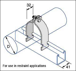
Figure 13 – Unistrut restraint support
The fire main in all locations should be supported as required by the pipework coupling system manufacturer, directly in contact with the support, i.e. not loosely suspended with studding/pipe strap and as constrained by the design of the structure.
Header Tank
WRAS specifies that the water supply must be from a dedicated uninterruptable supply, fed directly from the towns’ main. The connection should be made adjacent to the premises to be protected, and isolation valves should be installed on each town’s main connection, with non-return valves also fitted to prevent back siphonage which may contaminate the mains supply.
Header tanks should be positioned at the highest end of each system. The tanks should be thermally insulated, have close fitting insulated covers and be trace heated where necessary. The tanks should also include inlet float valve directly from the Towns’ main, high/low-level float switches, air vent, tank overflow and downstream pipes fitted with non-return valves to prevent tanks from back filling when the breeching inlet is in use.
Header tanks generally have an effective capacity of 500 litres and provide supplementary priming only.The supply shall only be used for firefighting purposes.
Frost Protection
All pipework and equipment that may be subject to temperatures below 4º C should be insulated and trace heated to protect against freezing. This is generally at the track entrance to portals, Breeching Inlets and intervention areas. The trace heating panel should also be monitored for faults by the fire alarm system.
Signage
Information should be provided, in a position available to the fire and rescue service, to indicate the type of system (i.e. wet or dry fire main) and the parts of the Station served by fire main outlets. For dry fire mains, information should also be provided indicating the maximum elevation and/or fall in relation to the riser inlet, and each floor level should have an indication of its elevation in respect to the fire main inlet.
Where multiple inlet points exist for an installation or for a number of installations at one location, permanent durable signage should be provided clearly indicating which inlet connection serves which fire main. The format of this signage should be discussed and agreed with the local fire and rescue service.
Calculations
All calculations describing proposed works and referencing drawings would be approved by the Fire Engineer, before procurement of all relevant materials. This would include the following;
- Friction Loss
- Flow Rates
- Thrust
Friction loss in pipe can be calculated using the Fire Protection industry standard Hazen Williams formula: –
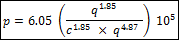
Where:
p = pressure loss in bar per meter
q = flow through the pipe in L/min
c = friction loss coefficient
d = internal diameter of the pipe in mmGalvanized steel pipe has a friction loss coefficient of 120.
Velocity in pipe can be calculated using the following formula: –

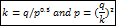
The discharge from a hose nozzle can be calculated from the formula below:

Where
q = flow in L/min
k = hose nozzle discharge coefficient or k-factor for head in Lpm/bar
p = pressure in barThis formula can be rewritten to give us:
Flow is defined as the quantity of fluid that passes a point per unit time. A simple equation to represent this is;
Flow (F)=Quantity (Q) Time (T)
Flow is sometimes written as ∆Q (rate of change of mass or volume).
In a Fire Main system without adequate supports, fluid flow velocities and internal pressures may create intolerable forces and tensions.
The calculator below is used to calculate the resulting force in a piping bend (Fig 14):
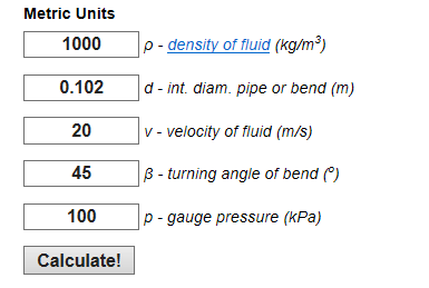
[Source: http://www.engineeringtoolbox.com/forces-pipe-bends-d_968.html ]


Where
Rx = resulting force in x-direction (N)
m = mass flow (kg/s)
v = flow velocity (m/s)
β = turning bend angle (degrees)
ρ = fluid density (kg/m3)
d = internal pipe or bend diameter (m)
π = 3.14…
Figure 14 – Example of forces
Barlow’s Formula
Barlow’s Formula is a safe, easy method for finding the relationship between internal fluid pressure and stress in the pipe wall. The formula predicts bursting pressures that have been found to be safely within the actual test bursting pressures.
It is interesting to note that the formula uses the “outside diameter” of pipe and is sometimes referred to as the “outside diameter formula.”

Where:
P = internal units pressure, in psi
S = unit stress, in psi
D = outside diameter of pipe, in inches
t = wall thickness, in inchesLaminar and Turbulent Flows
Laminar
In laminar flow the molecules of the fluid can be imagined to be moving in numerous layers or laminae as shown (Fig 15).

Figure 15 – Example of a laminar flow
Flow is usually considered to be laminar when a fluid flow through a tube and the rate of flow is low. This is unlikely to be considered for Fire Mains.
Turbulent
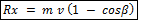
Not all fluid flow is laminar, but under certain physical conditions it becomes turbulent. When this happens, instead of the fluid moving in seemingly ordered layers, the molecules become more disorganised and begin to swirl with the formation of eddy currents, as shown (Fig 16).
 Figure 16 – Example of a turbulent flow
In this situation, flow is less ordered and the eddy currents react with each other, increasing drag or resistance to flow. As a result, a greater energy input is required for a given flow rate when flow is turbulent compared to when flow is laminar. This is best demonstrated by the fact that in turbulent flow, the flow rate is proportional to the square root of the pressure gradient, whereas in laminar flow, flow rate is directly proportional to the pressure gradient. This means that to double the flow, the pressure across the tube must be quadrupled.
Turbulent flow occurs when fluids flow at high velocity; in large diameter tubes and when the fluids are relatively dense – this is likely in our systems.
Learning Legacy
The Fire Strategy for the Station will almost certainly necessitate some deviations from the recommendations in the British Standard. They should always be discussed and agreed with the authority having jurisdiction and the local fire and rescue service.
The generic design principles that require discussion are:
- Landing valve/hydrant outlet selection – do we need to specify a High Pressure valve for a sub-surface location?
- Provision of a pressure gauge with bypass test facility at low-level intervention points to assist the Fire & Rescue Service with live information.
- Fault rectification kept to a minimum by utilizing standardized components and adequately “zoning” areas into maintainable sections.
- Supplementary information located at each system Breeching Inlet which would inform the F&RS what the system covers, if it has other inlet points, distance from inlet to lowest landing valve, drainage facilities and approximate horizontal length of the system.
- Maintenance regime based on the components and not based on “Dry Riser” requirements.
Informative Reference Documents
- Crossrail Fire Safety Engineering Principles CR-TSD-015
- BS 9990, Code of practice for non-automatic fire-fighting systems in buildings
- BS 9999, Code of practice for fire safety in the design, management and use of buildings
- BS 5306-0, Part 0: Guide for selection of installed systems and other fire equipment
- BS 5041 (all parts), Fire hydrant systems equipment
- BS 1710, Specification for identification of pipelines and services
- BS EN ISO 7010, Graphical symbols – Safety colours and safety signs – Registered safety signs
- LU Category 1 Standard 1-080 The Application of Fire Safety Engineering Principles to London Underground Premises
- LU Category 1 Standard 1-082 Active Fire Protection Systems and Portable Fire Equipment
- Office of the Deputy Prime Minister – Effect of reduced pressures on performance of firefighting branches in tall buildings 2004
- Fire-Fighting Flow-rate Barnett (NZ) – Grimwood (UK) Formulae
- Delta Fire Ltd
- The Engineering Toolbox
- Fire Brigade Fire Safety Guidance Note – GN29
- Anvil International Pipe Fitters Handbook
Conclusion
The provision of fire mains is an essential element of the fire protection systems in large and complex buildings due to the difficulties in providing water supplies at the point of use for fire-fighting and search and rescue. It is essential that these systems be carefully maintained to ensure instant readiness when required.
It is also essential that the authority having jurisdiction and the Fire & Rescue Service (F&RS) have a system that can become as commonplace as the standard “Dry Riser” without the need to bolt on complicated equipment. The following should be acknowledged when designing the system;
- Misinterpretation of drain valve sizes – valves should be sized to take into account the pipe bore, i.e. 100mm – 150mm requires a 50mm drain valve. Only Breeching Inlets should be fitted with a 25 mm drain valve, in accordance with BS 5041-3.
- Isolation valves required for ease of maintenance – continuous pipe runs should be designed to enable part closure without affecting the remainder of the system.
- Addition of pressure gauges at each intervention point – this would enable the operator to check the current pressure of the system.
- Signage relevant to the system including F&RS liaison – it is essential that the signage relays as much information as possible about the system to assist the F&RS.
- Addition of permanent flow test arrangement.
-
Authors

Gerry Mullan EngTech MIFireE - Crossrail Ltd
Gerry worked in the Crossrail MEP team until July 2017
