Implementation of energy saving initiatives in design review
Document
type: Technical Paper
Author:
Wing Fung PhD MSc BSc(Eng) CEng MCIBSE, ICE Publishing
Publication
Date: 09/07/2018
-
Read the full document
1 Introduction
One of the important elements in the Crossrail design assurance plan was to carry out a thorough review of each Contractor’s design against the project functional and performance requirements. The criteria of review include life cycle costs, environmental sustainability, efficient, safety, reliability, maintainability, accessibility and consistency across stations shafts and portals. Changes were made to the design as a result of the review process. These changes will result in a better integrated design with higher operational efficiency.
This paper reviews the energy saving initiatives implemented to the design of the mechanical, electrical and public health (MEP) installations in Crossrail stations.
This paper is based on a study using a simplified energy model based on a typical underground station (hereafter called the Reference Station). The projected energy saving with each of the design enhancement initiatives is represented in the energy model after adjustment made to account for the applicability to stations (whether to a single station or to all stations). The energy use in the Reference Station is expressed in terms of Normalized Energy Units (NEU) instead of the conventional kilowatt Hours. The annual power consumption of the Reference Station is the weighted average of the projected power consumption in underground stations in the Crossrail Central Operation Section.
This paper presents a first order appraisal of the possible energy savings with the enhancement initiatives implemented, using the limited information available at the time of study. A more accurate assessment of the energy performance of the station systems will be carried out at a later stage of the project life cycle in accordance with BREEAM recommendations [1]. Energy saving for implementing enhancement initiatives for individual stations can be worked out from the results for the Reference Station, after adjustments made to the station size and complexity, and other location specific considerations.
2 Reference Station
The energy use in a typical Crossrail station is primarily made up of Lifts and Escalators, Heating Ventilation and Air Conditioning (HVAC), Railway Systems (tunnel ventilation, signalling and communication systems), Lighting (for front of house and back of house areas), and Small Powers (ticketing machines and barrier gates, staff welfares and miscellaneous MEP systems like sump pumps and fire detection and suppression). The apportionment of the total energy use for each of the above common usage categories is shown in Table 1. Figures from a similar railway project are adopted in the Table as the Crossrail station design deliverables do not include prediction of energy use for MEP installations. More details of the predicted electricity consumptions in the Reference Station are shown in Appendix A Part 1 of this paper.
Table 1- Contributions to the total energy use in the Reference Station
MEP services (Functional Categories) Contribution to Annual Energy Use NEU Lifts and escalators 30% 300 Heating ventilation and air conditioning 30% 300 Railway Systems 20% 200 Lighting 15% 150 Small Powers 5% 50 In the study, the merits of implementing enhancement initiatives will be worked out with reference to the baseline information provided in the Reference Station. The energy savings will be expressed as the percentage energy saving for the enhancement initiatives and aggregate saving against the respective functional category.
3 Energy Saving Initiatives implemented
The following sub-sections provide an overview of each of the energy saving initiatives and an assessment of the potential energy saving that can be achieved with the implementation of the initiatives. A summary of the analysis results will be presented in the following section in this paper. More details of the analysis can be found in Appendix A Part 2.
Improve station power transformer efficiency
Transformer efficiency is the ratio of its output power to input power. At low load transformers have low efficiency as hysteresis losses (magnetization and demagnetization of core of transformer) and eddy current losses dominate over output power. Transformer efficiency increases as the load on a transformer increases. Most transformers reach their highest efficiency at a load point that results in coil loss equalling core loss. In a typical transformer working at low utilisation factor (30-50%), the transformer efficiency increases by 0.2% for 1% increase in load. The peak efficiency point will vary depending on the relationship between core losses and conductor losses.
In Crossrail stations, the estimated utilization factor for each functional category is shown below:
Table 2- Utilisation factors for the functional categories in Crossrail Stations
MEP services Estimated Utilization Factor Lifts and escalators 60% Heating ventilation and air conditioning 50% Railway Systems 30% Lighting 60% Small Powers 30% On the basis of the above, the overall utilization factor of the station transformers is likely to be less than 50%. The actual utilization might be even lower if a safety margin is included in sizing the transformers and/ or larger transformers are procured because of size gaps. Another contribution factor to low utilisation is that two transformers were designed to share the demand. With the predicted operating condition, running efficiency of the station transformers will therefore increase with incremental increase in utilization factor.
In the design review, an attempt is made to work out a more accurate prediction of the station load schedule and utilization factor. This will help optimise the maximum operating load hence improve the transformer operation efficiency. It is not uncommon for contractors’ load assessment schedules to assume unrealistically high power demands (high safety margins included) and utilisation factors (0.9 to 1.0) for the MEP and railway systems equipment. For example, Crossrail have advised in the design review that a Tunnel Ventilation diversity factor should be lowered to 0.3. Another example is on escalators. A diversity factor of 1.0 was often assumed in design calculations. Crossrail’s view is that 0.75 would be a more suitable value for the nature of use in Crossrail stations (as the escalators will be travelling in the up and down directions). The adoption of higher than actual load and utilization tends to drive up the maximum operating load. This will subsequently result in over sizing transformer and power transmission and drive down the operation efficiency of the transformers.
The design review under this part has only met with limited success because of the general lack of test information to support the rationalization of load and utilization. The design cut off date imposed by the power system designers on the size of station transformers also prevents the optimized load schedule and utilization reviews to be reflected in the final power system design. It is anticipated that 0.5% increase in transformer efficiency can be achieved through more accurate prediction of station loads/ utilization and optimized transformer sizing.
Use of LED lights and Lighting Control
Latest advances in optics and electrical LED packages, lamp shape and management methods result in LED solutions that reduce lighting related energy use. They also minimise the environmental impact due to frequent lamp replacement and remove the use of mercury in LED lamps. Crossrail requires that LED lighting should be used as far as practicable. On the basis that the station designs had already adopted high efficient fluorescent lamps before the LED decision was made, it is estimated that 20% of energy saving can be achieved with the design enhancement. The energy saving represents the improvement of LED technology over fluorescent lamp/ electronic ballast systems [2] which was included in the preliminary design.
On lighting control, Crossrail requires that DALI lighting management system be used in all stations. A DALI system provides a more effective way of lighting control for both front-of-house and back-of-house areas. The use of motion sensors also maximise energy saving. PIR switches are employed for lighting control in rooms that are not normally attended. As a result of the initiatives to better manage lighting control, a further 2% reduction in lighting power consumption can be achieved. The reduction is based on savings achieved in typical retrofit projects on DALI lighting control.
Use of Solar Photovoltaic (PV) panels
Crossrail has encouraged station designers to include photovoltaic systems in the design of roofs and canopies where applicable. PV systems will be fully integrated into the architectural and harness clean and free energy from the sun. The latest design of PV panels utilises Building-integrated photovoltaic modules of mono-crystalline solar cells. A software programme will help configure the best arrangement of the PV cells to optimise the energy yield in relation to the orientation and shape of the canopy structure. The power produced from these arrays will serve a part of the operational needs of the station. The projected power generated by the stations warrants it being fed directly into London’s grid, thus achieving maximum efficiency and providing London with surplus power.
However, the amount of free roof spaces in Crossrail underground stations is very limited and that most of the operation related services will require a high level of resilience. Space constraint and low pay-back limit the extensive use of PV systems in Crossrail stations. Only one worksite has managed to find roof space to install a PV system. An estimate saving of only 0.615% of the station small powers can be achieved with the use of solar panel.
Combining minor ventilation requirements into a common system and reduced ventilation rates
It is a common practice to develop separate cooling and ventilation systems to satisfy different functional needs. Adopting this approach in Crossrail stations might lead to maintenance problems because of the tight overhead MEP delivery space in service corridors. Optimising the number of systems that require the use of service delivery space will help cut down costs and problems in future plant maintainability and accessibility. In the design review, station designers were encouraged to group ventilation and cooling requirements for small staff rooms, utility rooms and toilets into a common ventilation and cooling system. Total capital and recurrent costs for a number of small cooling and ventilation systems are likely to be high as compared to a combined system. There are applications where the longer service route/ delivery costs with a combined system will outweigh the gains with fewer working plant and higher operational efficiency. The latter however will not be applicable to Crossrail as most plant rooms and accommodation in Crossrail stations are close to each other. The energy saving is contributed by the gain in fan motor efficiency (saving partly offset by the additional duct friction losses).
Crossrail encouraged the use of minimum ventilation rates for fresh air and the adoption of diversities of use/ utilisation factors to air systems used for cooling. Significant air flow rate reductions have been obtained leading to energy savings.
Energy reduction of approximately 0.377% of the energy use for HVAC in the Reference Station can be achieved through the implementation of the enhancement initiatives.
Selection of energy recovery plant for air exhaust systems
Crossrail has encouraged the use of devices in ventilation systems to recover heat between the intake and exhaust airstreams. In energy terms alone, recirculation of air is the most efficient form of heat recovery since it involves little or no energy penalty. However, recirculation is only possible if the ventilation rate is fixed by cooling rather than ventilation needs, and is therefore only applicable to all-air systems. The air quality implications of recirculation can also limit its use. There are three common types of heat recovery devices in the market that could be adopted for the purpose [3]:
Run-around coil- Finned air-to-water heat exchangers are installed in the ducts between which the heat is to be transferred. A water circuit is used to transfer heat from the warm extract air to the cooler supply air or vice versa in summer (see Figure 1). An expansion tank is required to allow fluid expansion and contraction. Overall heat transfer efficiencies are relatively low, as it is a two-stage heat transfer process. Crossrail does not encourage the use of run around coils because they are inefficient to operate and involve additional water circuits in the underground station.
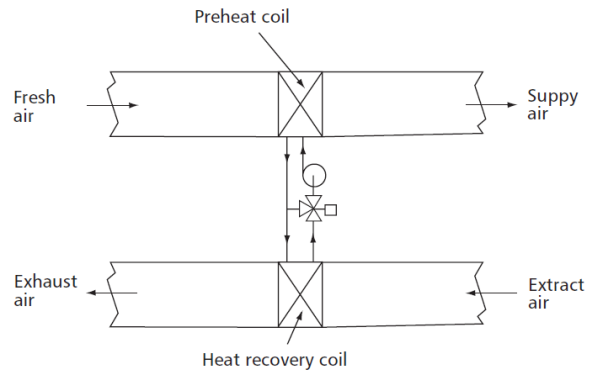
Figure 1- Run around coil
Recuperators usually take the form of simple and robust air-to-air plate heat exchangers (see Figure 2). Their efficiencies depend on the number of air passages and hence the heat transfer area between the two airstreams.
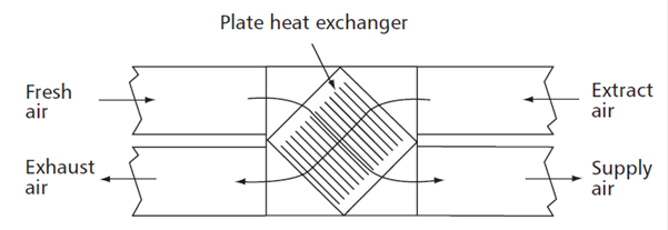
Figure 2- Recuperators
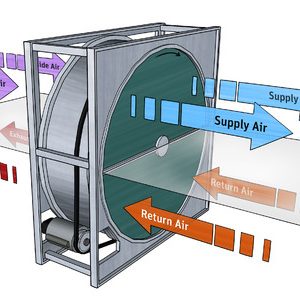
A thermal wheel comprises a cylinder, packed with a suitable heat transfer medium that rotates slowly within an airtight casing which bridges the ducts between which heat is to be transferred (see Figure 3). Thermal wheels are generally quite compact and achieve high efficiencies due to a counter flow configuration.
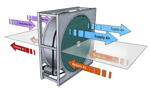
Figure 3- Thermal Wheels
Energy reduction of approximately 0.5% of the energy use for HVAC in the reference station can be achieved through the implementation of the enhancement initiative. The energy saving is contributed by the replacement of run around coils in the preliminary design with recuperators which have a higher heat reclaim efficiency.
Omission of pressurisation system for evacuation stairs and smoke clearance systems
In the design review, pressurisation systems for evacuation stairs and smoke clearance systems have been included in the stations design in many instances. This is over and above the Crossrail baseline requirement. These provisions were removed from the design after consulting the London Fire Brigade and clarifying the technical requirements in the station fire safety report. Although there are significant savings in capital and maintenance costs, saving in energy consumption is small because they are intended for emergency use only. It is estimated that an approximate 0.005% reduction in the energy use can be achieved through the implementation of the enhancement initiative.
Omission of Platform Cooling System
Preliminary stations’ design allowed for chilled air to be supplied to the platform to maintain temperatures at a comfortable level, on an assumption that the full height platform screen doors will limit air movement between the platform and tunnel. As the design of platform screen doors progressed, it was apparent that there is a much higher infiltration rate through the screen doors. The cooling strategy is no longer feasible and would not work without significant station redesign, which will inevitably lead to a much higher station energy need. In a subsequent platform temperature analysis, it was found that by relying on natural ventilation for the platform the absolute maximum heat index experienced at any public area on the platform is no greater than 32oC with a mean platform dry bulb temperature of no greater than 27oC for 97.5% of the hours in a design summer year as defined by CIBSE [4]. On the basis of the ventilation study, the provision of platform cooling system was omitted from the design. The peak platform temperatures and the number of hours per year that over-heating occurs will generally increase with time. These increases are driven by climate change and predicted rises in tunnel temperatures. The platforms may require additional cooling for limited scenarios after many years of operational use. The station designs have retained space proofing for an air-conditioning system with the view of retrofitting later during a ventilation system refurbishment, should it be required.
It is estimated that a reduction of approximately 8.44% of the energy use for HVAC in the reference station will be achieved through the implementation of the enhancement initiative.
Omission of glycol from the cooling water circuits
In Crossrail, there are situations where parts of the chilled water circuits are exposed to the outdoor environment. To prevent freezing in cold weather, station designers introduce either electric trace heater circuits or require the use of a water glycol mixture. For the latter, this will alter the viscosity and other physical parameters including specific heat capacity and pressure drop through the system. The knock on effect on the use of a glycol mixture is that the loss of heat transfer efficiency in the heat exchangers and appropriate allowances must be made for these effects when selecting components including the pumps and heat exchangers. Higher pressure drop will also increase pumping energy consumption. Based on life cycle costs consideration, Crossrail encouraged station designers to replace the use of a glycol water mixture in the cooling water circuit with trace heating. It is estimated that a reduction of approximately 1.05% of the energy use for HVAC in the reference station will be achieved through the implementation of the enhancement initiative.
Relaxation in temperature control set points and omission of unnecessary cooling systems
Room temperature design set points and tolerances are specified by station designers in accordance with the nature of use. In Crossrail stations, many rooms are considered to be under close temperature control as they are fitted with electronic cubicles. In conventional cooling designs for railway equipment, the most demanding environmental requirements are for rooms housing electronic control cubicle. Electronic components are designed to operate over a specified temperature range with upper limits generally set at 70°C for commercial applications, 85°C for industrial applications, and 125°C for military applications. Electronic circuitry operates best and most reliably at lower temperatures. Today’s more complex and smaller device dimensions along with closer packing result in higher heat density and elevated operating temperatures. Higher operating temperatures decrease the service life of the device or module. Any temperature sensitive materials used in a module can degrade and wear out more quickly. Other failure mechanisms, such as metal migration, can occur, particularly when both high temperature and humidity conditions are present. Here, metal whiskers or dendrites can grow from the conducting lines. With lines being spaced closer together in today’s devices, shorts between lines can occur and cause device failure. Additionally, when temperatures fluctuate, device interconnections and other components can fatigue from expansion and contraction due to thermal stresses and eventually fail. Higher temperatures also increase the electrical resistance of the conducting lines within a device or module, slowing the signal speed and reducing performance. As devices become more complex, conducting paths become longer and this performance reduction is more significant. For all of the above reasons, it’s critical to minimize the temperature of the electronics by designing efficient ways of carrying away their generated heat.
To address the above concerns, modern railway control equipment, including electronics, are already designed and constructed to work efficiently under a wider operational conditions and temperature fluctuations. Crossrail has suggested that temperature controllers, for MEP rooms, accept a wider range of room temperatures with, for instance, an upper limit of temperature of 25 0C under normal condition.
On the basis of such a relaxation in room temperature swing, UPS backup of the HVAC system serving critical plant rooms is not required and many of the small cooling or mechanical ventilation plant can be replaced with mechanical/ natural ventilation plant respectively. Furthermore, the number of cooling hours for MEP plant rooms will be much reduced. An energy reduction of approximately 4.5% of the energy use for HVAC in the Reference Station can be achieved through the implementation of the enhancement initiative.
Use of Enhanced Capital Allowance (ECA) products
The ECA Scheme for Energy Saving Technologies encourages businesses to invest in energy-saving plant or machinery specified on the Energy Technology List (ETL) which is managed by the Carbon Trust on behalf of Government [5]. The ECA scheme allows businesses to write off the whole cost of the equipment against taxable profits in the year of purchase. This can provide a cash flow boost and an incentive to invest in energy-saving equipment which normally carries a price premium when compared to less efficient alternatives. The ETL specifies the energy-saving technologies that are included in the ECA scheme.
Although the project is not eligible for the tax benefits under the scheme, Crossrail requires contractors to use ECA products where applicable. This will ensure that energy efficient products are being used for the project. Through adopting this strategy at the material compliance review (part of the technical assurance review), Crossrail can ascertain that energy efficient products are being used. A reduction of approximately 0.5% can be achieved in the HVAC energy use for the Reference Station.
Eliminate hot redundancy for cooling and ventilation systems
Many of the ventilation fans and cooling units in Crossrail stations are fitted with duty and standby to meet system reliability requirements. There are different regimes to maintain the desired level of readiness of the standby plant. Cold redundancy is for those processes where response time is of minimal concern and may require operator intervention or automatic control action upon receipt of a failure feedback signal. Typical service disruption time is in the order of up to 3 minutes. Warm redundancy is used where time is critical but a momentary outage is still acceptable. In this scenario, a momentary ‘bump’ can be expected. During this ‘bump’, the valves, motors and other devices might shutdown temporarily, and the sensors may not report back to the PLC system during the ‘bump’. Typical service disruption time with warm redundancy is in the order of 2-3s. Systems that require starting of high capacity motors are unlikely to meet the performance criteria for a warm redundancy system. Hot redundancy is used when the process must not go down for even a brief moment under any circumstance. To ensure that a hot redundancy system operates correctly, data needs to be transferred from the primary processor to the secondary processor with every logic cycle to ensure data integrity.
In the design reviews, it was noted that many of the designs proposed to adopt a ‘hot standby’ configuration. Crossrail subsequently confirmed that ‘cold standby’ is more applicable to station services to avoid over complexity in system control. A reduction of approximately 0.819% of the energy use for HVAC in the reference station can be achieved through avoiding continuous running of standby fans, pumps and chillers.
Initiatives raised in the review but not pursued further
The following is a list of initiatives that were not pursued further after the review. Implementation of these initiatives will be difficult as they either incur extensive abortive design work or they involve unproven technologies.
- Provision of a local ventilation system for Uninterruptible Power Supply (UPS) cubicle in lieu of HVAC for the whole UPS plant room.
- Connection to the Central Emergency Power Supply System (CEPS) operated by the London Underground will reduce the size of the UPS by up to 60%. This results in savings on capital and operation costs (smaller plant to be cooled and fewer batteries to be replaced).
- Recovery of heat generated from the station transformers.
- Heat recovery from tunnel linings.
4 Summary of energy use in the Reference Station
Table 3 provides a summary of the energy saving initiatives implemented in the Crossrail design review and their impact on the energy consumption model.
Table 3- Summary of energy saving achieved for the initiatives implemented in the design review
Energy Saving Initiative Nature of Energy Saving Initiative Applicable Energy Use in Reference Station (NEU) Energy saving (%). See Appendix A Part 2 for details Applicable line wide (%) Energy saving (NEU) % energy saving for the respective energy use category Energy Use in Reference Station upon implementation of initiative (NEU) 1 Improve station power efficiency All 1000 0.5 100 5.000 0.5 995.0 2 Use of LED Lights and lighting control Lighting 150 22.0 100 33.000 22.0 117.0 3 Use of solar PV panels Small Powers 50 4.92 12.5 0.308 0.615 49.7 4 Combining small plant and reduced ventilation rates HVAC 300 0.503 75 1.132 0.377 298.9 5 Heat recovery plant HVAC 300 2.0 25 1.500 0.5 298.5 6 Omission of stair pressurisation HVAC 300 0.037 12.5 0.014 0.005 300.0 7 Omission of platform cooling HVAC 300 11.25 75 25.313 8.438 274.7 8 Omission of glycol from cooling circuits HVAC 300 2.1 50 3.150 1.050 296.9 9 Relaxation in temperature set points and omission of unnecessary cooling HVAC 300 4.5 100 13.500 4.5 286.5 10 Use of ECA products HVAC 300 0.5 100 1.500 0.5 298.5 11 Omission of hot redundancy HVAC 300 1.31 62.5 2.456 0.819 297.5 Aggregate energy saving in NEU 86.934 The energy use for each functional category of MEP services before and after implementation of energy saving initiatives are shown in Table 4 below:
Table 4- Summary of energy saving under each functional category in the Reference Station
Normalised Energy Unit (NEU) Aggregate saving (NEU) Percentage saving in power consumption Revised NEU Lifts and Escalators 300 298.5 0.500 326.9 HVAC 300 249.9 16.68813 273.7 Railway Systems 200 199.0 0.5 217.9 Lighting 150 116.3 22.5 127.3 Small Powers 50 49.4 1.1145 54.1 Total 1000 913.1 1000 The implementation of energy saving initiatives and the associated change in energy use apportionment for each category of energy use are illustrated in the following pie/ bar charts:
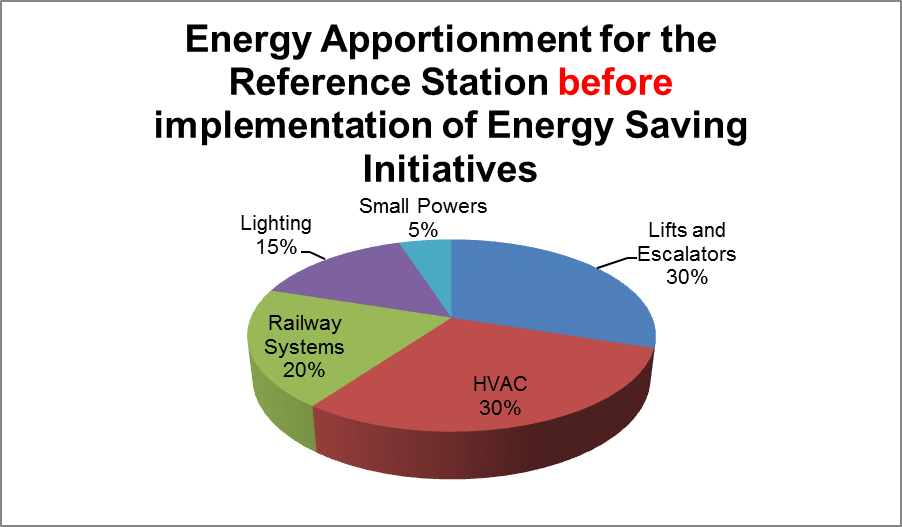
Figure 4- Energy apportionments for the Reference Station before implementation of the energy saving initiatives
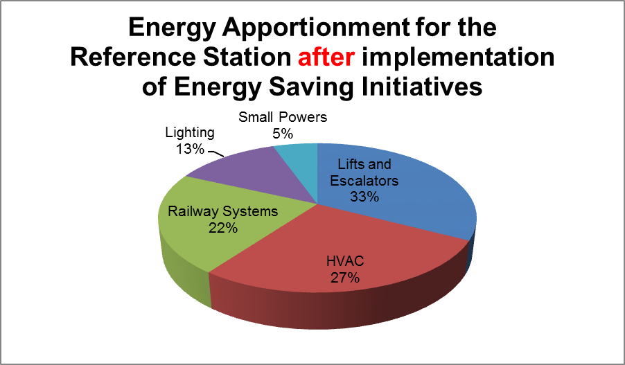
Figure 5- Energy apportionments for the Reference Station after implementation of the energy saving initiatives
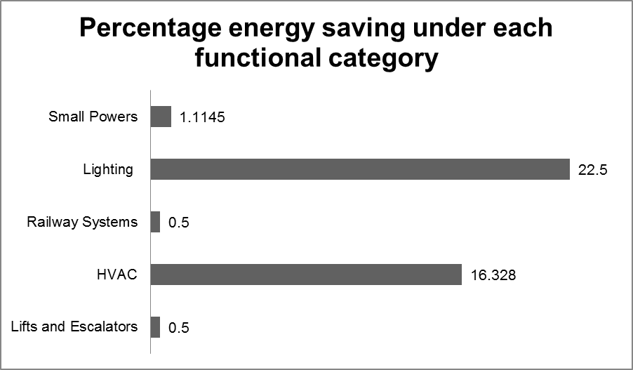
Figure 6- Percentage saving in energy consumption for each functional category in the Reference Station
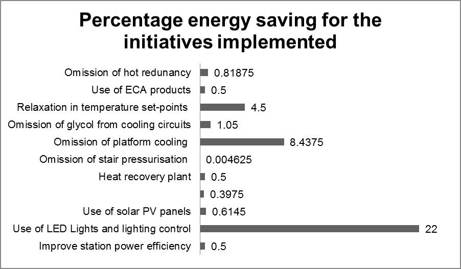
Figure 7- Percentage saving in energy consumption for each of the initiatives implemented in the Crossrail design review
5 Conclusion and Lessons Learnt
The design review process implemented in Crossrail has been effective in optimising the future energy use in Crossrail stations. Through the use of the normalised energy model, it can be shown that about 8.69% energy reduction will be achieved against the baseline energy consumption.
The lesson learnt from the design review process can be summarised as follows:
- It is more desirable that the client review be integrated in the concept, scheme and detail design process to minimise the extent of ‘design change’ and impact on construction programme.
- The adoption of design enhancement initiatives should make due consideration to such elements as cost of design change including impact on delivery programme. A suitable balance has to be maintained. If the review is taking place early on in the design, the latter consideration should not occur.
- If the project programme does not allow a thorough client review on the design, the review should focus on ‘high benefit low implementation cost’ items (easy win) items.
- The client review should consider the reduction of energy-in-use, using known and mature technologies against other criteria including first cost, maintenance costs and complexity of operation.
- Sharing of best practices among work packages.
6 References
[1] “Building energy and environmental modelling CIBSE Applications Manual AM11: 1998” CIBSE 1998
[2] Hilary Graves and Cosmin Ticleanu “LED Lighting- A review of the current and future developments” BRE 2011
[3] “CIBSE Guide B Heating, ventilating, air conditioning and refrigeration” CIBSE 2005
[4] “CIBSE Guide A Environmental design” CIBSE 2006
[5] “The Enhanced Capital Allowance scheme for energy-saving technologies- A guide to equipment eligible for Enhanced Capital Allowances” The Carbon Trust 2012
7 Appendix A
7.1 Part 1 Electricity consumption for the Reference Station
The estimated figure for total electricity consumption for the 8 underground stations in the Crossrail Central Section, from preliminary BREEAM energy assessment, is 35,562,925 kWh per annum
Annual electricity consumption for the Reference Station in the energy model
= 35,562,925/8
= 4,445,365 kWh
Table 5- Annual Electricity Consumption for the Reference Station
MEP services Contribution to Annual Energy Use Normalised Energy Unit (NEU) Apportionment (kWh) Lifts and escalators 30% 300 1,333,610 Heating ventilation and air conditioning 30% 300 1,333,609 Railway Systems 20% 200 889,073 Lighting 15% 150 666,804.75 Small Powers 5% 50 222,268.25 100.00% 1000 4,445,365 7.2 Part 2 Basis of estimate for energy saving initiatives:
Improve station power efficiency
Number of stations applicable: All
Assume that for a typical transformer working at low utilisation factor (30-50%), the transformer efficiency increases by 0.2% with 1% increase in load.
Assume Crossrail station transformers are operating at 30-50% utilisation factor and 2.5% improvement in utilisation could be achieved.
Percentage saving= 2.5×0.2/1.0= 0.5%
Use of LED Lights and lighting control
Number of stations applicable: All
Assume 20% reduction in consumption with LED lighting system over fluorescent lamp/ electronic ballast system.
Assume 2% reduction in consumption through more effective lighting management system with DALI.
Percentage saving= 20+2= 22%
Use of solar PV panels
Number of station with PV panels: 1
For the station that is provided with PV panels,
Number of panels: 66
Yield per panel: 270 W
Assume Number of hours per day in operation: 8
Assume Yield Factor: 0.7
Assume miscellaneous correction factor: 0.3
Annual electrical energy harnessed= 66x270x365x8x0.7×0.3/1000= 10,927 kWh
Percentage reduction= 10,927×100/ 1333609= 0.819%
Combining small plant and reduction of ventilation rates
Number of stations applicable: 6
Combining small plant
For a typical station,
Assume total fan power of the combined system: 2 kW
Assume motor efficiency gain less increase in duct losses: 5%
Assume correction factor to actual running load: 0.8
Assume utilisation factor: 0.75
Annual saving= 2X0.05x365x24x0.8×0.75= 525.6 kWh
Percentage saving= 525.6×100/1333609= 0.0394%
Reduction of ventilation rates
For a typical station,
Assume total air flow reduction: 1 m3/s
Assume system resistance: 600 Pa
Assume fan motor and drive efficiency: 85%
Annual saving= 1x(600/1000)x365x24/0.85= 6183.5 kWh
Percentage saving= 6183×100/1333609= 0.464%
Aggregate percentage saving= 0.0394+0.464= 0.503%
Heat recovery plant
Number of stations applicable: 2
For a typical station,
Assume contribution of cooling load to total HVAC load: 50%
Assume outdoor air load to cooling load: 20%
Assume efficiency gain with Recuperators over run around coils: 20%
Annual saving= 1333609×0.5×0.2×0.2= 26672 kWh
Percentage saving= 26672×100/1333609= 2.0%
Omission of stair pressurisation
Number of station applicable: 1
Assume reduction in total fan power with the omission of systems: 82 kW
Assume annual run time: 0.5 hour per month
Annual saving= 82×0.5×12= 492 kWh
Percentage saving= 492×100/1333609= 0.0369%
Omission of platform cooling
Number of stations applicable: 6
For a typical station,
Assume annual cooling load for the platform cooling system: 100000 kW
Assume energy efficiency ratio: 0.667
Annual saving= 100000/0.667= 150000
Percentage saving= 150000×100/1333609= 11.25%
Omission of glycol from cooling circuits
Number of stations applicable: 4
For a typical station,
Assume contribution of cooling load to total HVAC load: 50%
Assume contribution of chilled water production to total cooling load: 70%
Assume increase in chiller efficiency and lowered pump power without glycol: 6%
Annual saving= 1333609×0.5×0.7×0.06= 28005 kWh
Percentage saving= 28005×100/1333609= 2.1%
Relaxation in temperature set points and omission of unnecessary cooling
Number of stations applicable: All
For a typical station,
Assume room where no cooling will be needed: 32oC
Assume design room temperature in preliminary design: 22oC
Assume contribution of cooling load to total HVAC load: 50%
Assume portion of cooling area fitted with temperature controller: 30%
Annual saving= 1333609 x ((25-22)/(32-22)) x 0.5×0.3= 60012 kWh
Percentage saving= 60012×100/1333609= 4.5%
Use of ECA products
Number of stations applicable= All
For a typical station,
Assume contribution of cooling load to total HVAC load: 50% (where energy saving could be achieved through the use of more efficient chillers/ unitary products)
Assume contribution of chillers/ unitary plant to total cooling load: 20%
Assume efficiency gain through the use of ECA products: 5%
Annual saving= 1333609×0.5×0.2×0.05= 6668 kWh
Percentage saving= 6668×100/1333609= 0.5%
Omission of hot redundancy
Number of stations applicable= 5
For a typical station,
Assume fan power saving and miscellaneous efficiency gains= 2 kW
Annual saving= 2x365x24= 17520 kWh
Percentage saving= 17520×100/1333609= 1.314%
-
Authors

Wing Fung PhD MSc BSc(Eng) CEng MCIBSE - Arcadis
Technical Director (MEP), Arcadis
Wing is is a Chartered Engineer with over 30 years’ experience as a technical specialist engaged in mass transit system planning, design, project management, technical assurance, commissioning, energy management, operation and maintenance, and asset renewal. Wing has been with the Crossrail project in the CRL Chief Engineer Group since 2013, overseeing mechanical design, systems integration and T&C.
Specialties: Building Services, Mechanical Engineering, Computational Fluid Dynamics, RAM studies, Systems Integration, Requirement Management, Testing and Commissioning.
