Information Management System to Handle Maintenance Alarms from MEP Installations at Crossrail Stations, Shafts and Portals
Document
type: Technical Paper
Author:
Wing Fung PhD MSc BSc(Eng) CEng MCIBSE, ICE Publishing
Publication
Date: 30/09/2017
-
Read the full document
Introduction
Maintenance related alarms are captured by the station electronic data information systems (Building Management System, SCADA and equipment control panels etc.) and communicated to the appropriate reporting centres so that they can be recorded and responded to in a structured and timely manner. This will necessitate a clear definition of the alarms and precise location of reporting centres to where these alarms are to be communicated.
This paper sets out the principles as to how maintenance related alarms are managed in Crossrail; the line wide reporting infrastructure for maintenance alarms, and typical maintenance alarm management matrices in stations, shafts and portals. This paper reviews the approach to manage maintenance related alarms generated from mechanical electrical and public health (MEP) installations at Crossrail stations, shafts and portals. The approach maintain a consistent management approach on maintenance alarms and is in alignment with the intended line wide alarm reporting infrastructure during revenue operation. This will also support verification of Reliability Availability and Maintainability (RAM) performance parameters (incident response time etc.) used in the RAM analysis. A clear definition of the alarm reporting channel will confirm that the response times (Mean Time To Repair, Incident Response Time) used in the RAM analysis are achievable in the RAM Demonstration Report.
This document is not intended to cover follow up actions by Maintainer upon receipt of these maintenance alarms at the respective reporting centres, non-MEP related maintenance alarms (railway systems, customer services systems, commercial/ retails systems etc.), non-Crossrail MEP systems in interchange stations, track side premises and train operation related alarms.
Basic Principles of Maintenance Alarm Management System
An alarm management system is developed to address usability requirement. Alarm systems should be designed to meet user needs and operate within the operator’s capabilities. This means that the information alarm systems should be relevant to the operator’s role at the time; indicate clearly what response is required; be presented at a rate that the operator can deal with; and be easy to understand. Furthermore, the contribution of the alarm system to protecting the safety of people, the environment or the plant equipment should be clearly identified. The performance of the alarm system should also be assessed during design and commissioning to ensure that it is usable and effective under all operating conditions. Alarms are provided to reduce the likelihood of sub-optimal plant operation or of plant damage, as these may lead to injury to people, environmental damage and/or economic loss. It follows that the design and engineering of the alarms and alarm system should consider both the functional and integrity requirements relative to the level of risk they are intended to reduce.[1]
Maintenance alarms are signals which are annunciated to the Maintainer, typically by an audible sound, some form of visual indication, usually flashing or by the presentation of a message or some other identifier. An alarm will indicate a problem requiring Maintainer action generally initiated by a process measurement passing a defined limit setting as it approaches an undesirable or potentially unsafe value. It may also indicate equipment status becoming unhealthy. Every alarm (or combination of alarms) should have some response which should have been clearly defined by the designer of that alarm. If a response cannot be defined, then the signal should not be an alarm.
Maintenance Alarms included in the design will be system/ asset related i.e. assets that are defined under a unified convention (in the case of this project, Crossrail AD4 Convention). They should be relevant, not spurious or of low maintenance value and timely, not long before any response is needed or too late to do anything. Most important of all, they have to be prioritised, indicating the importance to which the Maintainer deals with the problem and understandable, having a message that is clear and easy to understand.
Some of the key considerations for alarm system design are:
- Risk assessment- to identify alarms to protect against safety, environmental or economic risks
- Common Man Machine Interface (MMI) template on reporting of maintenance related alarms
- Consistency of maintenance alarm management matrix line wide for stations, shafts and portals
- Systems integration aspects where different systems have to function in tandem to relay alarm messages
- Alarm system configuration (hardware and software)
- Well defined testing and commissioning requirements.
In determining the required alarm processing for each device state within the system the following guideline should be applied:
Alarm– Attention must be drawn to the Maintainer that a device status has changed to something that may impact the operation or safety of the equipment and that an action is required to resolve the situation. Any alarm should always be acted upon immediately by the Maintainer unless a higher priority alarm exists even if the action is only to decide that the problem does not require resolving immediately. A clear distinction should be made in the design between alarms and alerts.
Alerts– Alerts are always of lower priority than alarms and ignoring an alert does not normally place a demand on a safety system without first triggering an alarm. When an alert occurs it does not signify that the plant has moved outside of its normal operating envelope or that immediate action is required by the Maintainer to prevent an abnormal situation. Alerts may be suppressed in abnormal situations.
Event– A change in a device status must be recorded for later analysis i.e. maintenance, incident analysis, etc.
Indication– A change in a device status is required to be presented as a graphical change only.
Situation related alerts may be configured in the Building Management System (BMS) on an ad-hoc basis by the Maintainer and therefore do not require inclusion in the alarm management system. With the hierarchical architecture of the system the most overriding principle relating to the alarm philosophy is to ensure that the user does not get an alarm flood from all associated equipment in the event of a sub-system failure. To ensure against alarm flooding specific mechanisms can be engineered within the system.
The key to an effective alarm management system is that the reporting centres will not be flooded with excessive alarms. This can be achieved through scrutinising the list of alarms and prioritising their relative importance and sending the alarms to the appropriate reporting centre. An alarm list is the mechanism by which the system manages alarms. An alarm entry is placed in the alarm list by the component item raising the alarm. Each component may generate one or more entries, where each entry is related to a specific condition of the component, e.g. an emergency fan component may generate separate alarm entries on both ‘fan running’ and ‘run hours’. The information for each entry held within the alarm list to provide the alarm process includes:
- Time and date of alarm
- Time and date of alarm acknowledgement
- User name of acknowledging Maintainer
- Alarm characteristic
- Alarm group
- Zone
- Priority
- Text description
- Alarm state
- Acknowledge status
- Asset Tag identification
- Associated mimic.
A change in the alarm state of an item e.g. acknowledgement, causes the previous alarm list entry for the condition to be replaced by the new alarm entry. Any change to the alarm list entry for an item within the alarm list generates an appropriate event log entry.
An event log is the mechanism by which the system maintains an electronic record of all activities classified as requiring storage for later analysis. An event entry is placed in the event log by the item determining the event. By definition an alarm condition automatically classifies as an event, therefore an alarm list entry will propagate an event log entry. The information for each entry held within the event log to provide the event log process includes time and date of event, event type, zone, priority, text description, tag identification, and alarm indication.
The event log is maintained by deletion of the oldest existing entry prior to insertion of a new entry, in effect a rolling log. If events are deleted from the event log that have not been archived then a persistent alarm is generated.
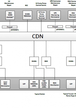
Maintenance Alarm Reporting Infrastructure
Appendix A shows the System Architecture for the Maintenance Alarm Management System. For Stations, BMS allows remote access via internet on a site by site basis. Maintainer can interrogate individual outstations as and when necessary. Critical maintenance alarm messages will be sent via emails to designated addresses. For shafts and portals vital maintenance alarms that require remote monitoring will be connected to the SCADA. This is irrespective of whether the portal or shaft has a BMS or not. For the former, the BMS will operate as a local control and monitoring system.
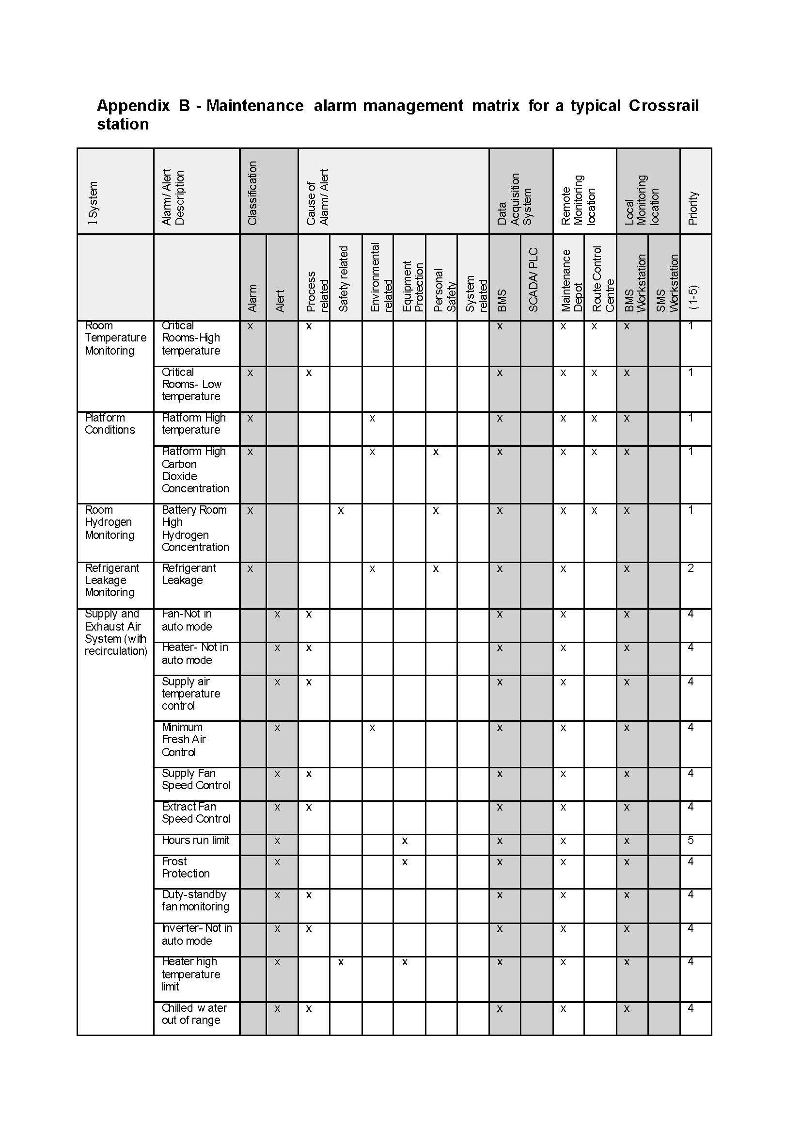
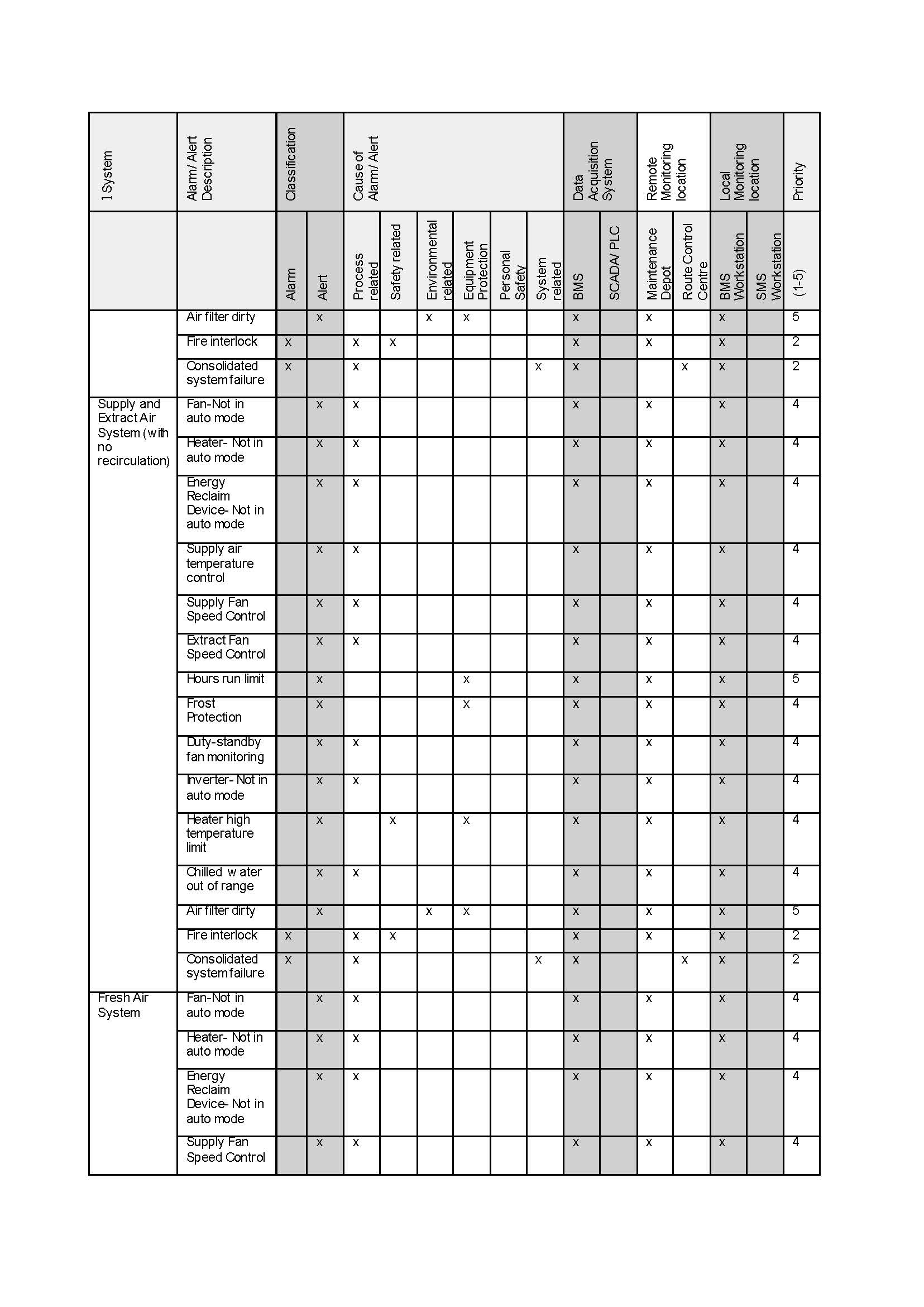
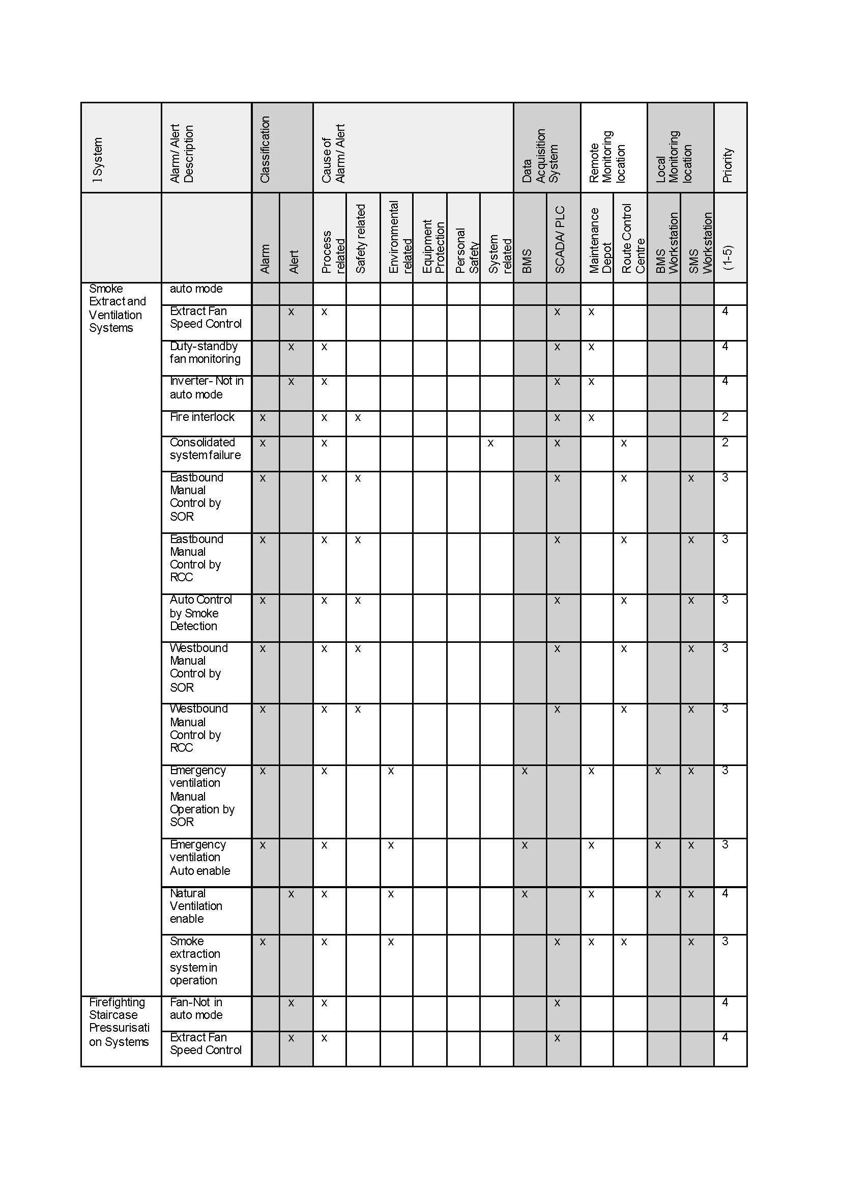
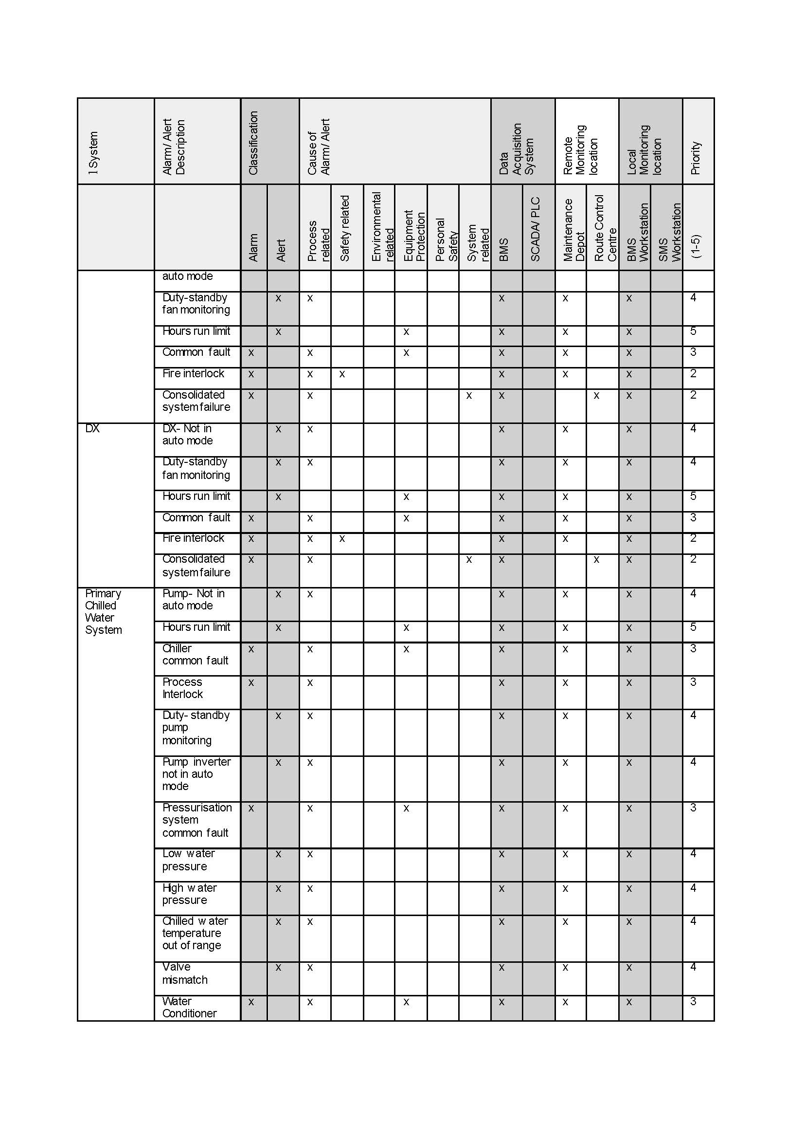
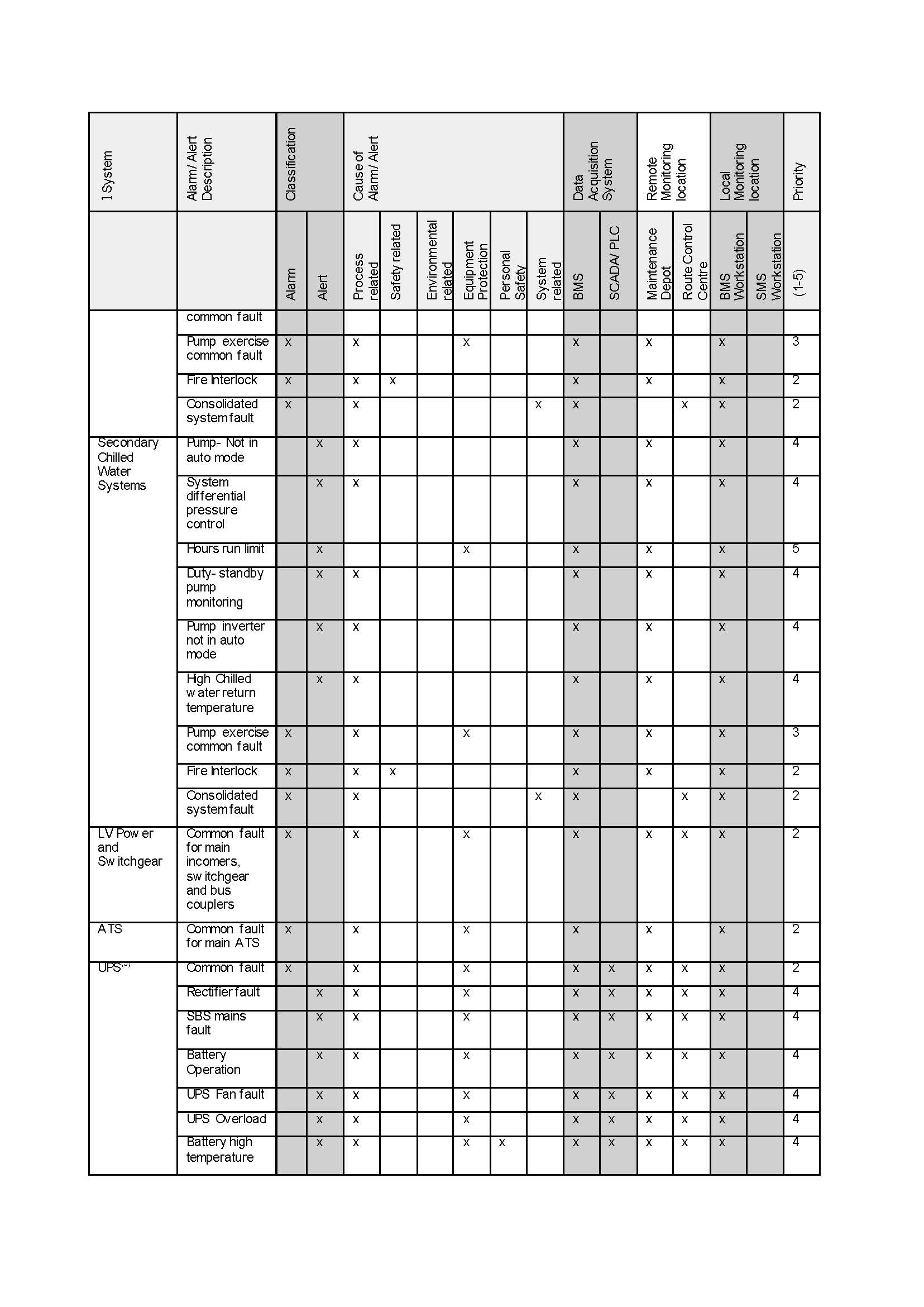
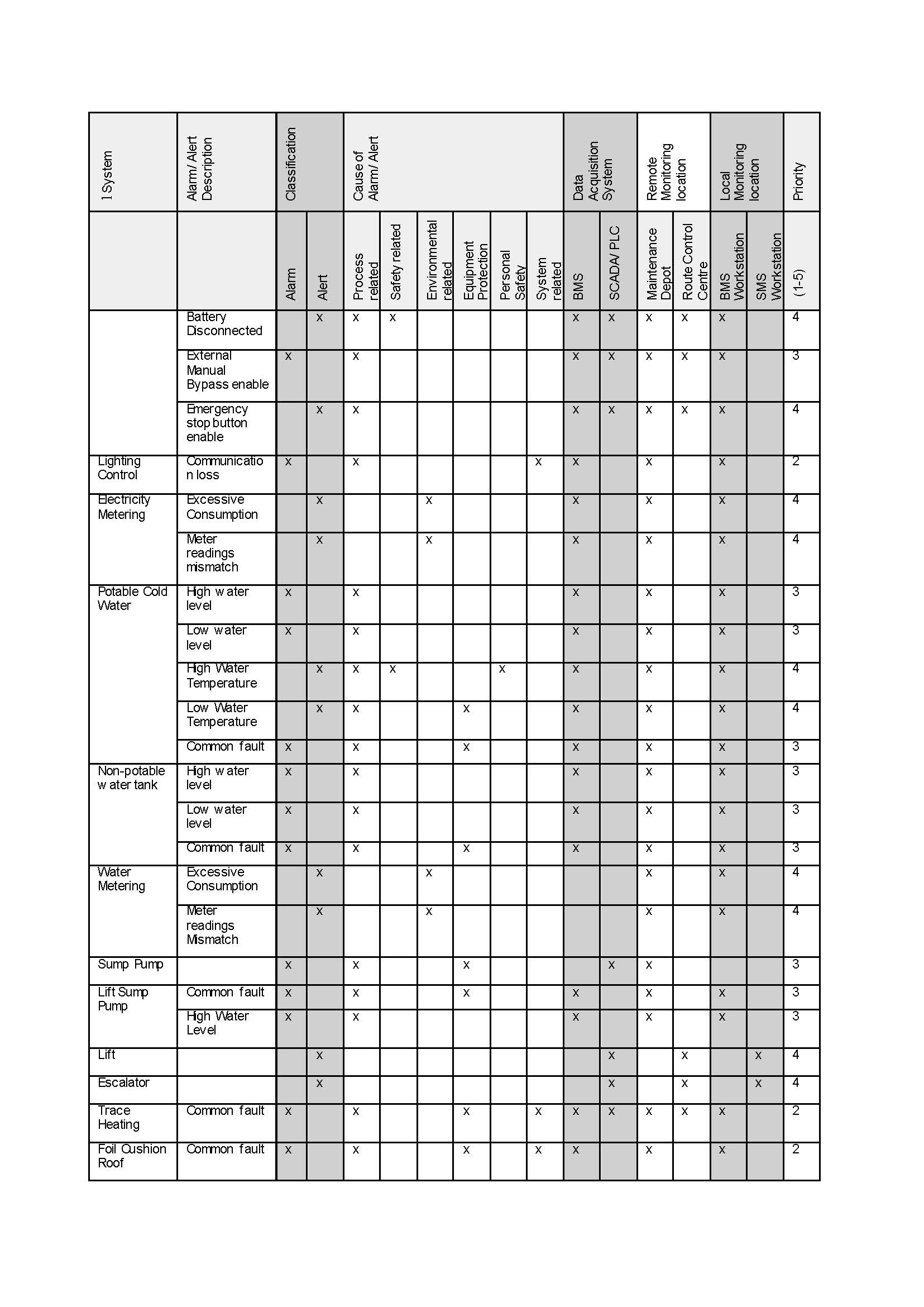
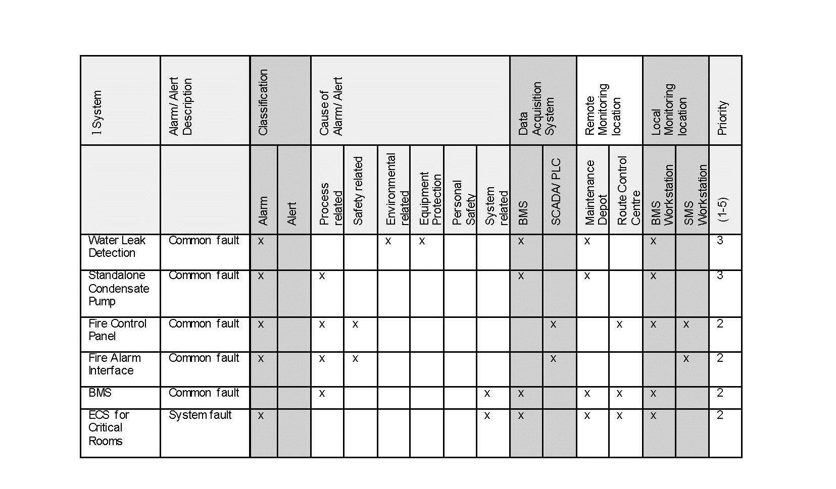
Maintenance Alarm Management System Matrix
Appendix B provides an illustration of a maintenance alarm management matrix for a typical Crossrail station.
Technical Assurance Evidence for an effective maintenance alarm management
Some of the evidence of an effective Maintenance Alarm Management System is:
- A risk based Maintenance Alarm Management System has been adopted.
- The system is compatible with the line wide alarm management infrastructure.
- The structure and format of alarm reporting is consistent with line wide maintenance alarm management design.
- A comprehensive and co-ordinated maintenance alarm management system matrix is developed.
- Testing and commissioning requirements of Maintenance Alarm System are included in Inspection Test Plans (ITP). In particular, end to end testing requirements have been identified and included in the test plan.
- Successful completion of all agreed deliverables on maintenance alarm management. The list of deliverables includes but not limited to System Architecture for management of maintenance alarms and maintenance alarm management matrix for the particular station, shaft or portal.
References
[1] EEMUA Publication 191 “Alarm systems- A guide to design, management and procurement” Edition 3, The Engineering Equipment and Materials Users’ Association, 2013
Appendix A – System Architecture for Management of Maintenance Alarms


-
Document Links
-
Authors

Wing Fung PhD MSc BSc(Eng) CEng MCIBSE - Arcadis
Technical Director (MEP), Arcadis
Wing is is a Chartered Engineer with over 30 years’ experience as a technical specialist engaged in mass transit system planning, design, project management, technical assurance, commissioning, energy management, operation and maintenance, and asset renewal. Wing has been with the Crossrail project in the CRL Chief Engineer Group since 2013, overseeing mechanical design, systems integration and T&C.
Specialties: Building Services, Mechanical Engineering, Computational Fluid Dynamics, RAM studies, Systems Integration, Requirement Management, Testing and Commissioning.

