Installation of Optical Fibre based Sensors within Sprayed Concrete Lined Tunnels to measure Strain and Temperature
Document
type: Technical Paper
Author:
Joe O’Donnell, Dr Giorgio Nosenzo, James Preston, Tom Sturman, ICE Publishing
Publication
Date: 03/11/2014
-
Read the full document
Requirements for Monitoring
Monitoring is a vital requirement throughout the whole life of an underground structure to assess its performance in resisting the forces applied to it from the surrounding ground and other structures. This monitoring takes place throughout the construction, and serviceability phases, and has been seen as essential by the British Tunnelling Society (BTS) and the Health and Safety Executive (HSE) report into the 1994 tunnel collapse at Heathrow.
From the findings of the HSE, the Heathrow tunnel collapse occurred for a number of reasons, one being that the tunnel monitoring instrumentation that had been specified by the designer was inadequate for monitoring crucial movements in the tunnel and the designer, as part of their design, had not set rates of change for allowable tunnel movement. According to the report, monitoring is vital in determining the behaviour of the tunnel lining and the surrounding ground. Unsatisfactory trends should be identified sufficiently early to enable corrective steps to be taken. Careful consideration has to be given to the number and location of monitoring points and direct measurement of the movement on a tunnel’s cross-‐section is the most vital and provides the most easily interpretable data.
Traditional methods of tunnel strain measurements involve the measurement of points around the perimeter of tunnel profile with the use of geodetic prisms and surveying equipment. The position of the prisms is measured at various time intervals and a displacement ascertained from subsequent readings. This displacement can be compared with the designer’s expected values, with certain limits requiring action to be taken to prevent further movement and the risk of potential structural failure. This method however requires many assumptions to be adopted and in the back calculation from displacement to strain. Another form of monitoring uses pressure cells that are fixed to the extrados of the tunnel and measure the force exerted upon the plate of known area. To be effective and provide reliable results however these cells (earth pressure cells) must be installed to the excavated face of the tunnel. This raises issues regarding the health and safety of operatives during installation due to working under non-‐supported ground. The reliability of information attained from pressure cells is also questionable due to the wide scattering of data and factors that affect their performance such as installation method.
Once a tunnel has been constructed and is in its serviceability phase, there are often different methods that are used to measure the performance and condition of the structure. These can include further measurement of geodetic prisms and analysis of movement and visual inspections.
Fibre Bragg Grating Sensors
Optical Fibres (OF) are flexible optically transparent fibres through which light can be transmitted by successive internal reflections. This type of transmission allows the propagation of a light signal along a fibre for very long distances with minimal attenuation. This ability to carry data over long distances together with the OFs capability of carrying a high number of different signals along a single fibre, are the reasons for their widespread use in telecommunication.
By exploiting the capability of external actions on a fibre to induce variations of properties to the light travelling within the fibre itself, a number of sensing techniques have been developed. Among the various techniques, Fibre Bragg Gratings (FBG) were selected as the technique that is best suited to providing accurate strain and temperature measurements. This technique is based on the use of selectively modified areas of special telecom-‐grade optical fibres that have the property of reflecting a narrow bandwidth signal centred on a certain wavelength. This is a function of a number of design parameters and shows the property of varying linearly when strain or temperature variations are applied to the FBG. This wavelength can be measured very accurately using a dedicated demodulation unit capable of converting the wavelength shift in a digital signal. By measuring the wavelength signal through an FBG, it is possible to turn an OF into an accurate strain or temperature transducer.
The use of FBG based sensors provides a number of benefits over other types that make them ideal for use in an underground environment. FBG based sensors are self-‐referencing because the sensing principle is based on a reversible physical modification of the FBG structure, a structure that does not degrade with the time. It is therefore possible to disconnect and reconnect the cables without having to recalibrate the sensors as they are self referencing and do not suffer from drift. Due to their operating principles and no moving parts, the operation of optical fibre sensors does not cause wear to the sensors or other parts of the sensing network making them highly resistant to the elements, allowing them to survive indefinitely in harsh environments. Sensing cables based on FBG technology typically have a diameter of 1-‐2 mm and therefore their inclusion in concrete structures does not affect the structural properties.
Regarding measurement performance FBG based optical sensing offers both high resolution and accuracy, for strain typically in the order of 1-‐2 micro strain and for temperature 0.1 degrees Centigrade, whilst being able to successfully perform dynamic measurements up to several kHz. Due to the nature of OF there is no interference caused from electromagnetic noise, and there is no effect on other systems. As they are transmitters of light there is also no risk of a spark, and no requirement for a power supply to each sensor location. The interrogator and data logger can be installed long distances away from the sensors, such as in an office above ground.
Each FBG reflects a signal that is a function of its design parameters; therefore FBGs can be employed in high numbers, e.g. up to 40 sensors on a single optical fibre (in-‐series multiplexing), a capability that is a unique feature of the FBG. The use of standard OF couplers and switches and the use of multi-‐channel interrogation equipment allow a number of different fibres to be connected to a single interrogation unit. This allows the creation of long term, large and sophisticated networks that can be used to provide real time monitoring of a structure.
Installation
The installation was undertaken at two locations within a concourse tunnel at Bond Street Station, one of largest sprayed concrete lined (SCL) tunnels at the station. The successful installation of FBG sensors within an SCL tunnel requires the availability of a sensor capable of surviving what is a very aggressive installation process, capable of seriously damaging most types of sensors. Many FBG sensors that are commonly available are too fragile to be used in such an environment. It was therefore necessary to use reinforced cables that had been previously proven to survive the spraying process.
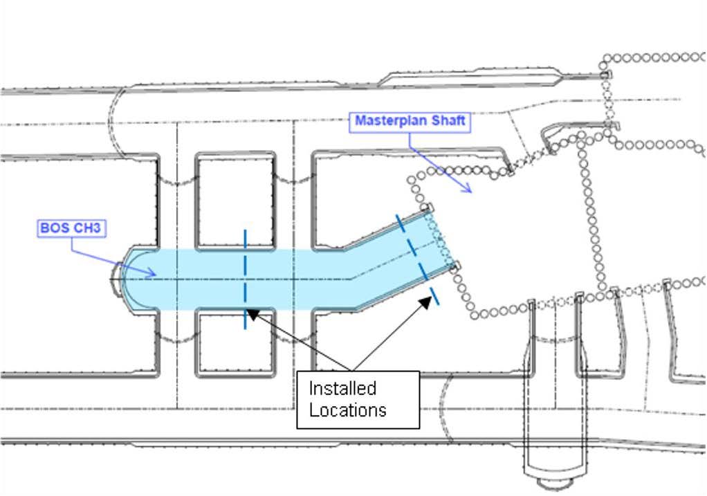
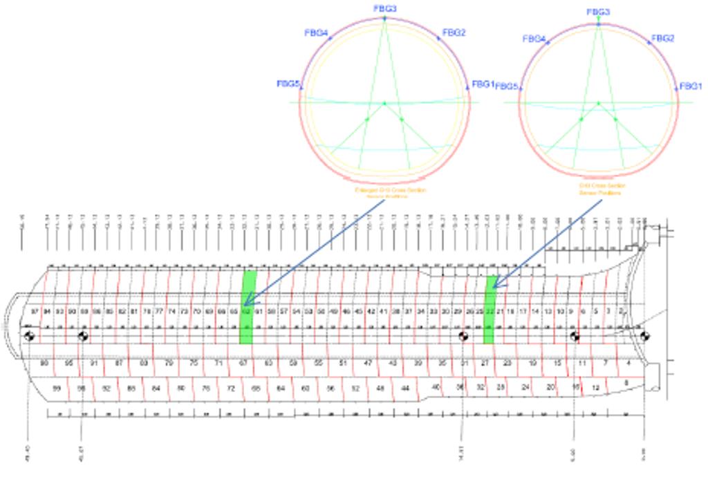
Figure 1 – Installation Location within Bond Street Station, Plan
Reinforced FBG sensing cables are based on the use of FBG arrays encapsulated in a small pultruded fibreglass rod 2mm in diameter. Even with the fibreglass reinforcing and external coatings the sensors still have near perfect strain transfer. This manufacturing technique allows the production of sensors within fibres that whilst being slender are also very robust, easy to handle and install. The robustness of these sensing fibres was further enhanced by the addition of an external nylon coating. This nylon coating makes the sensor more capable of surviving the mechanical effect of concrete being sprayed onto it. The overall diameter of the nylon reinforced sensing cables is 2mm.
The strain sensing cables used were characterised by the presence of 5 FBGs, each of them corresponding to one strain sensing positions within the initial heading of the tunnel. The location of the FBGs on each cable was designed so that each sensing point would be in the desired position around the tunnel profile. Each sensing cable was supplied with two connectors, one at each end. As FBG based sensors are connected to the interrogation units from one end only, this configuration introduces a degree of redundancy. If a cable or connector is damaged or broken it is possible to simply connect the cable from the other end, and acquire all the sensors along the full length of the cable up to the position of the break in the cable.
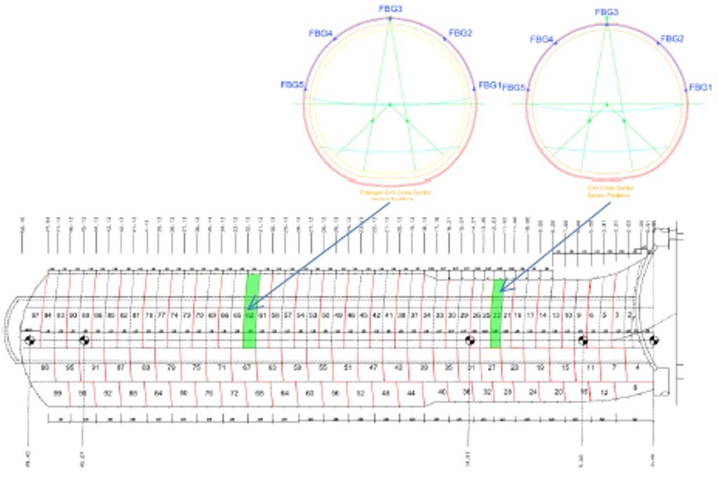
Figure 2 – Long Section through BOS CH3 tunnel showing installation locations.
Temperature sensing cables were also used with a dual purpose: to monitor the temperature variation during the concrete curing phase and also compensating any temperature effect on the strain sensing cables. Each installation was instrumented with a single FBG temperature sensing cable located near the tunnel axis of that advance. As a result of this configuration, temperature compensation for all strain sensing points in a section was supplied from the single temperature sensing point in the same advance.
In addition to the standard cable features, particular care was taken in providing reinforcements to the connectors of both strain and temperature sensing cables to guarantee the robustness of the sensing network.
The FBG sensing cables were interrogated using a dedicated FBG interrogation unit controlled by a local control computer. The interrogator selected was a Micron Optics Sm130 that was selected due to its dynamic interrogation capabilities, allowing the unit to interrogate up to over 500 sensing points at a frequency of 1 kHz. A wireless 3G connection dongle was installed on the control computer to allow the transmission of data to a remote server. This data was then viewable via an internet connection for any number of users with a logon to view in real time using DaMinS software.
Signals from the sensors were carried through optical fibre cables connected to the sensors via standard telecom grade optical fibre adaptors, with cables fixed along the length of the tunnel at the shoulder, and run to the surface via already installed service trunking.
The interrogation equipment and dedicated control computer were installed in the site office located at the top of the main shaft. The equipment was installed within a secure server rack designed to host internet & network components in order to provide protection against dust and dirt.
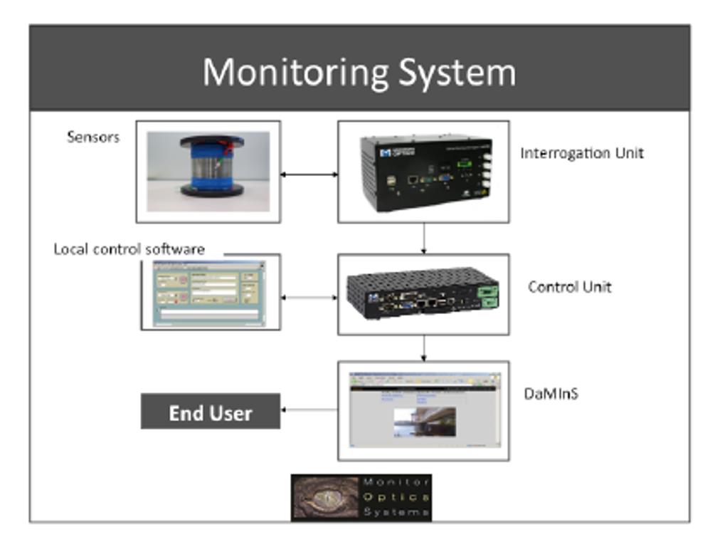
Figure 3 - Monitoring Installation Equipment
Signal cables were run through the shaft and to the predetermined location of the sensors connectors. The cables were inserted within conduits in the sections where they were most exposed to the risk of damage, such as along the length of the tunnel adjacent to construction activities, but were left unprotected in other areas where there was minimal risk of damage. The intrinsically passive nature of FBG signals made possible laying the cables in conduits together with electric cables without any risk of interference.
The sensors were installed onto the intrados of the initial 75mm lining once the minimum safe strength had been achieved for the safe entry of operatives. The installation of the strain sensors was achieved by positioning the sensing cables so that each sensing point corresponded to the level of the intended location, designated by a laser from surveying equipment. The sensing cable was then pinned in place using 30mm galvanised staples. These prevented any undesired movement of the cable during the concrete spraying process while at the same time not exerting forces on the sensors capable of altering the strain measurements. The survivability of the temporary fixings had previously been proven during a pilot tunnel installation.
The installation procedure for the temperature sensing cables was similar, with the only difference that the cables were fixed in a more limited number of points due to their shorter length. The installation of the sensing cables required the use of a Mobile Elevated Working Platform (MEWP) with a crew of two operatives in the basket in order to reach the tunnel crown. At the same time, a third person could complete the connection of the sensing cables to the pre-‐ installed signal cables.
Once the sensing cables were pinned in the correct position and connections confirmed by verifying the sensors provided data, spraying of the primary lining commenced that fully encapsulated the sensing cable within the concrete lining.
Data recording started immediately after the connection of the sensors to the interrogation unit through the sensing cables. This allowed the measurement of strain and temperature variations on the sensors during the concrete spraying and the early age strength development. The acquisition frequency was set at 1 acquisition per second although data was saved with a frequency of 1 data set per minute.
Results
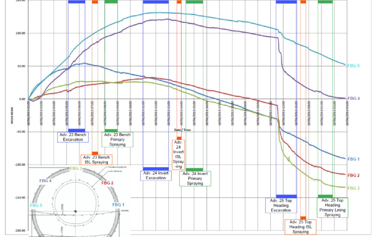
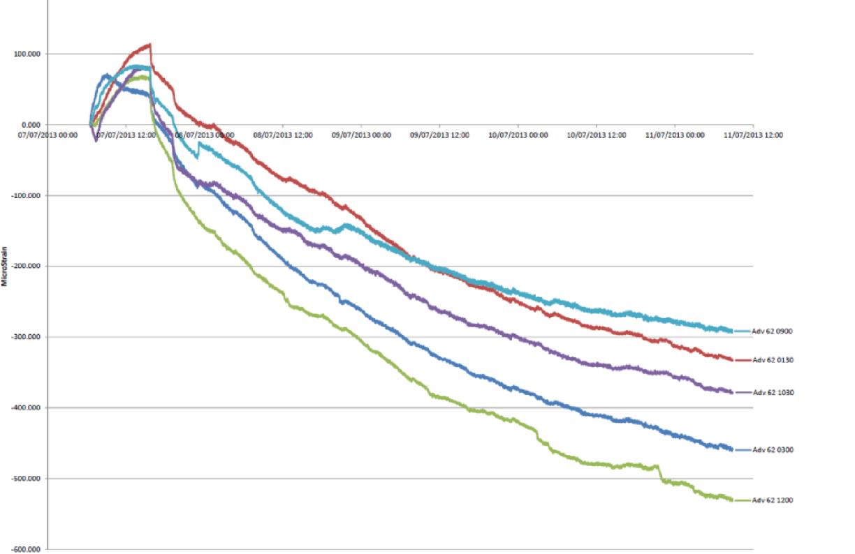
The results that were attained from the installations within advance 22 and advance 62 are shown in chart 1 and chart 2 respectively. Results have been referenced to zero when the spraying activity within that advance ended. There is also a timeline of events shown along the bottom of chart 1.
Chart 3 shows the temperature readings of the first installation, however is not calibrated to the correct temperature and so a relative temperature reading is only available.
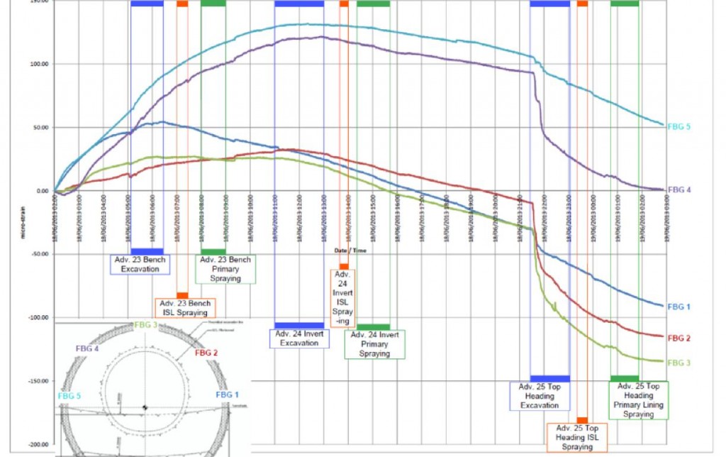
Chart 1 BOS CH3 Advance 22 SCL Top Heading Strain
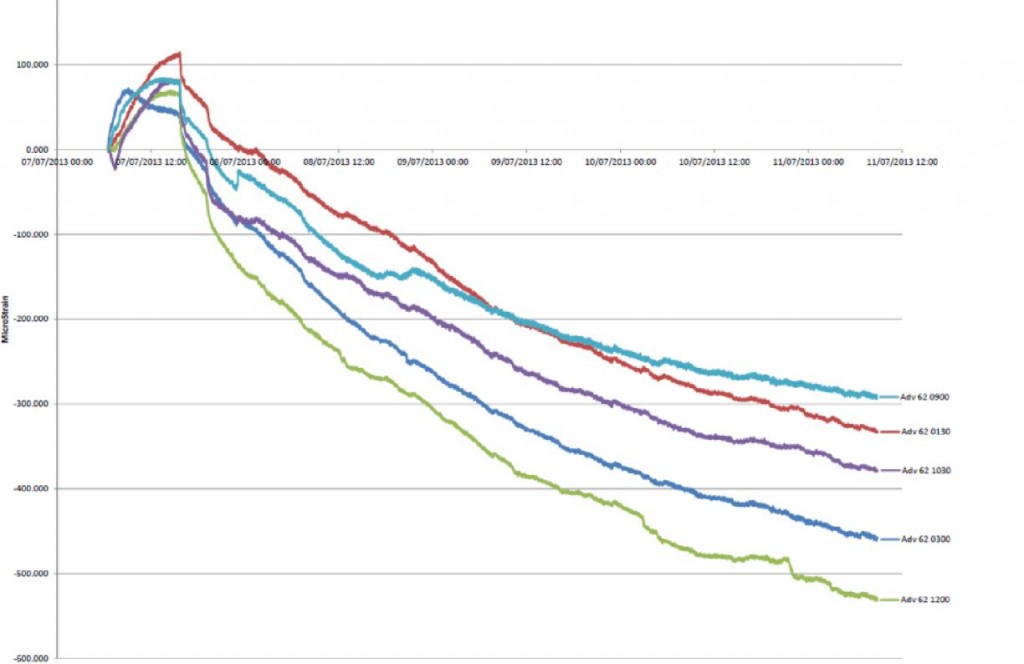
Chart 2 BOS CH3 Ch32 Baselined from Convergence monitoring reading (07/07/13 06:30)

Chart 3 BOS CH3 Advance 22 SCL Top Heading Temperature
Conclusions
It can be seen from both charts 1 and 2 that there was an initial contraction of the tunnel lining as the concrete initially cured, followed by an increase in micro strain, showing tension within the lining. After both installations, within approximately 24 hours all the sensors shown compression when compared to the base lined value once spraying had been stopped. There was also an increase seen in the compression of the lining at various stages during the subsequent stages of tunnelling. This was generally seen during the excavation stages, and was most pronounced during the first top heading excavation after the installations had taken place. This slowed once the exposed faces of the tunnel have been sprayed.
The increase in compressive strain can be attributed to the tunnel lining deforming as it takes loading from the surrounding London Clay. These deformations are mostly seen during nearby breaks within the tunnel lining due to unsealed faces, and are less pronounced once the tunnel ring profile has been completely sprayed up.
It was seen from chart 3 that the maximum temperature is reached approximately 7:30 hours after the encapsulation of the sensing cable.
Further Recommendations
It was noted that the temperature compensation sensor was installed near the left hand side of the tunnel above the axis. During the spraying process the lining commences from the axis and works upwards from both sides, before spraying the crown. Depending upon which side is sprayed first has an effect on the temperature compensation of the sensors within the lining during the early age strength development. Long term however, this would be negligible as it can be assumed that the tunnel would reach a consistent temperature around its profile at each chainage.
Further to the results that were provided from the two installations within BOS CH3 it would be advisable to expand the trial and install further sets of monitoring sensors within tunnels of varying profile. This would aid the comparison of data that can reviewed for a localised area with the assumption that similar loadings would be applied to the tunnel from the ground, and the effects of varying tunnel thicknesses and geometric profiles can be compared. To gain a further understanding of the temperature variation, and as such an estimate of the rate of the concrete curing, it would be necessary to instrument a profile with several temperature sensors. This would allow the temperature variations around the profile to be ascertained, as well as provide a more accurate temperature compensation for strain sensors within the lining. It would also be able to see if there are any local variations in temperature around the ring due to construction activities.
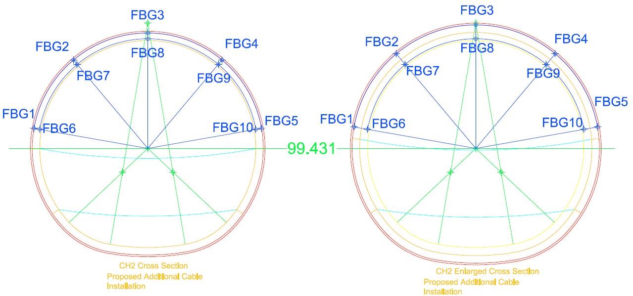
A further investigation would be the installation of sensors around the complete tunnel profile to see the behaviour of the lining around the temporary backfilled invert when it is being tracked upon by tunnelling plant, the installation of mechanical and electrical services, and tunnel finishes.
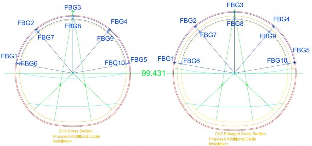
Figure 4 - Proposed Profile and Monitoring Sensor Locations
A further investigation is an installation of two sensor cables within the same advance, one near the intrados, and one near the extrados. This would allow the bending moments within the tunnel lining to be calculated.
References
Health and Safety Executive 2000 “The collapse of NATM tunnel at Heathrow Airport” HSE Books
British Tunnelling Society 2011 “Monitoring Underground Construction – A best practice guide” ICE Publishing -
Authors

Joe O’Donnell - BAM Ferrovial Kier
Graduate Design Engineer, Gary Gabriel Associates (formerly of BAM Ferrovial Kier)
Dr Giorgio Nosenzo - Monitor Optics Systems
Technical Director, Monitor Optics Systems
James Preston - Monitor Optics Systems
Business Development Manager, Monitor Optics Systems
Tom Sturman - Crossrail Ltd
Field Engineer, Crossrail