Installation of rigid overhead catenary in Crossrail tunnels
Document
type: Technical Paper
Author:
Alfred Satchell, Javier Zamorano MEng, Sergio Pellicer, ICE Publishing
Publication
Date: 09/07/2018
-
Read the full document
1 Introduction
1.1 Project Overview
The Crossrail Central Operating Section is formed by twin bore single track tunnels Royal Oak portal, Pudding Mill Lane portal and Victoria Dock portal, plus a separate open section at both sides of Connaught Tunnel and the Thames tunnel between North Woolwich and Plumstead portals, including intermediate shafts at Fisher Street, Stepney Green, Mile End, Eleanor Street and Limmo. C610 is the dedicated contract for the Systemwide Main Works Project where Alstom-TSO-Costain (ATC jv) is the Principal Contractor.
The Overhead Line Equipment (OHLE) system for this section is configured as 25kV traction power utilising Auto-transformer feeder (ATFS) and switching (ATS) stations, that will be fed from Pudding Mill Lane ATFS under the normal supply or from Kensal Green ATFS, via Westbourne Park ATS, as a back-up supply. The OHLE system is designed as a Rigid Overhead Catenary (ROC) in tunnels sections and an auto tensioned flexible Overhead Catenary (OCS) in surface sections allowing trains running up to speeds of 100 Kph.
This paper describes the installation method in the tunnel sections, focusing in the drilling operations and installation of supports, rigid overhead conductor and contact wire.
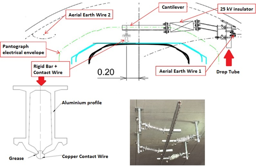
Figure 1: Scope of the Rigid Overhead Catenary System
1.2 Advantages of ROC system
The Rigid Overhead Catenary System is an overhead line feeding system for railways infrastructures which can be considered as an alternative solution to the standard flexible catenary and 3rd rail feeding systems that make it predominantly suitable for use in underground train infrastructures. The main advantages offered by this system are:
- Safety during the installation and maintenance, as the operatives don’t need to deal with radial loads which are one of the most common accidents in this industry. Furthermore, the system guarantees a higher safety level eliminating the risk of Contact Wire breakdown due to wear or accidental reasons, and for the impossibility of contact between live parts and structures or people.
- Maintenance is minimum compared to traditional catenary, due to the simplicity and robustness of its components, working with no moving parts without any mechanical tensile. The absence of tensile forces in the Contact Wire reduces the risk profile and the wire replacements. Furthermore, it reduces the likelihood of dewirement or snapping.
- The great surface area, improving the system’s own refrigeration and lowering the risk of melting by overheating. The great conductor section allows high level current intensities, eliminating the necessity of feeders and effectively reducing the radiation.
- A reduced installation height from track level is required due to the absence of the conventional catenary wire as well as to the simplicity of its supports, leading to a design of a small tunnel diameter. Using Tunnel Boring Machine (TBM) as excavation method, the internal diameter can be reduced up to 0.5m by adopting ROC system as compared to OCS for 25kV AC, resulting in a 6.2m internal diameter in the Crossrail tunnels. This advantage makes ROC rail systems so interesting for their application in tunnels, being increasingly chosen for city underground systems and main line tunnels.
2 Operation of the semi-automated tunnel drilling machine
Two separate machines first of its kind in the world, have been specifically designed for the Crossrail project to facilitate the drilling of the holes within the bored tunnel sections for the Overhead Line Equipment (3 holes every 9.6m plus additional supports on curves) and Earth Return Wire (1 hole every 600mm), the ME2 drilling rig has been manufactured by Rowa in Switzerland. The equipment consists of a Self-propelled Drilling Wagon, capable of running on railway and road modes.
Semi-automated tunnel drilling machine – design characteristics No. of drilling devices 13 pcs. 
Drilling hole diameter 14 mm Drilling hole depth 150 mm Drilling time for each hole 90 s Installed power 88 kW Hydraulic power unit max. 37 kW Length 15 m Width 3.2 m Maximum gradient 7.3 % Travel speed self-propelled 4 Km/h Maximum gradient 7.3 % Figure 2: Semi-automated tunnel drilling machine design characteristics.
Prior commencing work 3D Scan is conducted taking measurements to provide full details of the position of every segment within the tunnel including the position of all circumferential and radial joints and other features to provide key locations. The data from scan is processed using computer software that provides a comprehensive as built model of the tunnel to set out holes.
The main advantage of the study is that allows to resolve any clashes with no drill zones, testing coordinates of each hole position and identifying most preferred hole combination to minimise delays when on site. The output of this exercise are offset coordinates from centreline of the tunnel for the centre of each hole or each cluster of holes. Once the geometry parameters have been identified and the combinations and positions are known, the machine can commence the work.

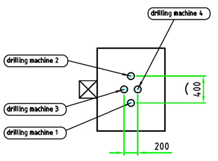
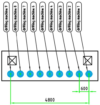
Figure 3: Drilling mode 1 and Master gauges of drilling modules 21 and 22
The drilling machine consists of a two-part wagon:
Lower wagon:
- Main chassis and Drives.
- Generator, Electrical & Control Cabinets. Including a combined hydraulic power unit with two pump assemblies, 37kW for travel drives and 15kW for operational components. The machine is equipped with a stationary diesel generator (with particle filter) for self-contained power supply. The hydraulic power unit runs with 400 VAC whilst the drills, vacuum units and portable power distribution board with 110 VAC.
- Walkways
Upper wagon:
- Carry the three mobile drilling modules (arms and chassis). Each module is made up of a carrier bracket that moves in longitudinal direction and a pivoted telescopic arm with the drilling equipment attached. A total of 13 combihammer drilling devices are arranged on the three different modules. Each drill assembly is equipped with a hydraulic cylinder that actuates the drilling stroke. The drilling dust is removed directly from each borehole by means of an extraction vacuum system that has been modified to improve the efficiency.
- Guidance system (rollers and laser). For exact positioning on the linear (z) and vertical (y) tunnel axis, each drilling wagon is equipped with two laser measurement systems consisting of one laser sensor for linear and two laser sensors for vertical distance measurement, allowing fine adjustment of position through hydraulic system. The drilling wagon processes are controlled by 8 sensors for distance measurement (steering cylinders, combihammer feed, telescopic arms, rotary drive, longitudinal-z direction, vertical-y direction), telescopic arm inclination and contact pressure.
This innovative plant has been designed to reduce and eliminate risks, the main benefits are:
Enhancement of Health and Safety of workers:
- Operatives are not in physical contact with the tools, eliminating Hand Arm Vibration (HAVs).
- The pertaining vacuum cleaners reduce the risk of breathing harmful dusk for operatives.
- Soundproof enclosures around each cluster of drills have been provided to achieve as low a noise level as practicable.
- Working at height minimised. Safety doors located at the wagon corners to restrict access to sides, in case of access violation the sensor cut power.
Environmental:
- An integrated borehole extractor extracts the dust directly at each drilling point, preventing the release of dust deposited within the tunnel environment. The machine is equipped with a total of 13 extraction points and vacuum cleaners.
Quality assurance:
- Setting out of holes undertaken in advance to eliminate clashes when in the tunnel.
- Increasing the accuracy of the setting out and drilling, through elimination of human error.
- The data for each hole position are stored and logged in the log file, enabling information for the operator on when a certain hole was drilled and which holes need to be re-drilled manually to avoid accumulation of error.
Improving progress rates:
- The drilling machine has been set a target to achieve a progression rate of in excess of 250m/shift. This equates to approximately 1000 holes within 8 production hours, minimising man hours within the tunnel. The drill time for hole is 90s with at Cycle time required of less than 10min, having achieved up to 400 linear meters of progress per day.
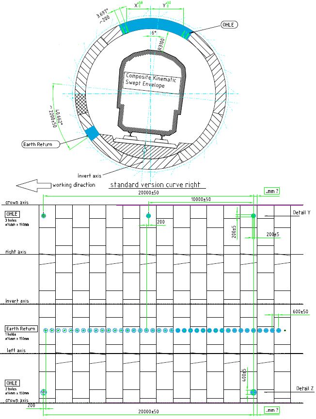
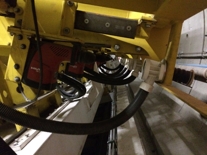
Figure 4: drilling scheme example and photographs
3 Installation of rigid overhead catenary system (ROC)
Following completion of drilling operations, the installation of the main elements of the Rigid Overhead Catenary can commence with the following characteristics:
3.1 Supports and Anchoring Systems
The brackets and structures that support the ROC beam are to be installed in the crown of the tunnel. As the tunnel curves different supports will be used to change the angle and stagger of the ROC to match the cant of the track. Each support is analysed separately and the correct angle and length of the support and Cantilever is selected depending on the location and considering tunnel geometry.
The standard Drop Tube will be composed by square tube 80x5mm welded on a horizontal or sloped base plate. The base plate shall be fixed with 3 anchor bolts, as this arrangement will allow for the greatest flexibility in making adjustments. The Cantilever is attached to the drop tubes using U-bolts with a torque value 40Nm and the torque value of bolts fixing insulators and cantilever is 70Nm.
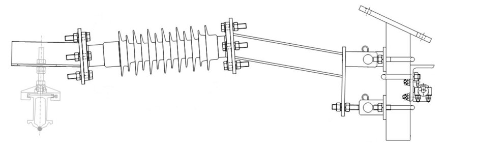
Figure 5: Schematic of Cantilever installed in tunnel
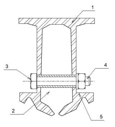
The hanger clamps that carry the weight of ROC are made of aluminium alloy for high mechanical resistance, high corrosion resistance and no galvanic corrosion with aluminium profile. The clamp side is also pivoting to avoid a rigid constraint on the bar.
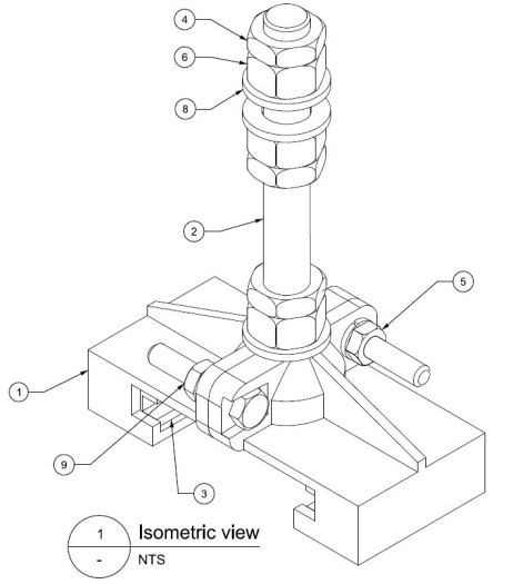
Item Description Material Qty. 1 Half clamp Aluminium alloy 2 2 Threaded axe Stainless steel AISI 316L 1 3 Bushing Nylon 2 4 Nut M16 EN 5589 Stainless steel A2 3 5 Screw M8x50 EN 5739 Stainless steel A4-70 min. 2 6 Nut M16 EN 5588 Stainless steel A2 3 7 Spring washer A8.4 EN1751 Stainless steel A2 2 8 Flat washer Ø17×30 EN 6592 Stainless steel A2 2 9 Nut M8 EN 5588 Stainless steel A2 2 Figure 6: Details of Hanger Clamp
3.2 ROC bar
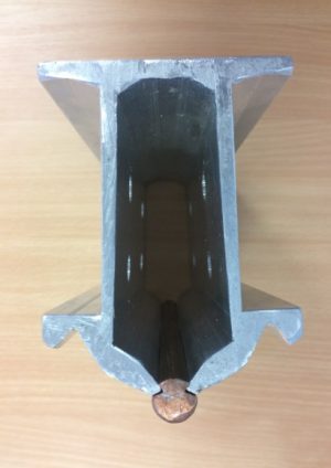
The Rigid Overhead Catenary bar is an aluminium profile supported from a hanger clamp by insulated cantilever arm and a drop tube support fixed to tunnel roof (as previously described), that accommodates a 150mm2 copper contact wire. The nominal length of a standard bar will be 10m which is also the maximum length of the bar, so the weight will not exceed 60kg.
The profile has a gap in the bottom to allow for insertion of the contact wire using a railcar, each length of bar has 8 holes drilled in each end to allow for jointing with bolted joint plates. The beam has regular drainage holes on its underside made at a distance of 4m from one to another, to ensure that any condensed water build-up in the bar itself is discharged.
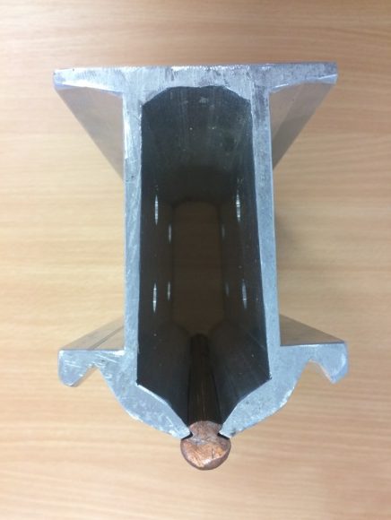
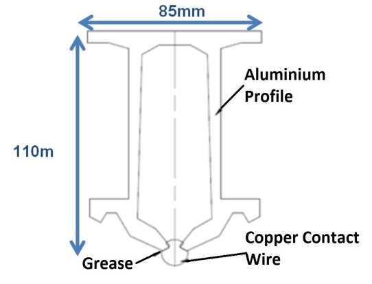
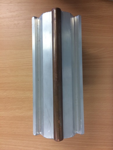
Figure 7: Details of ROC bar and Contact Wire
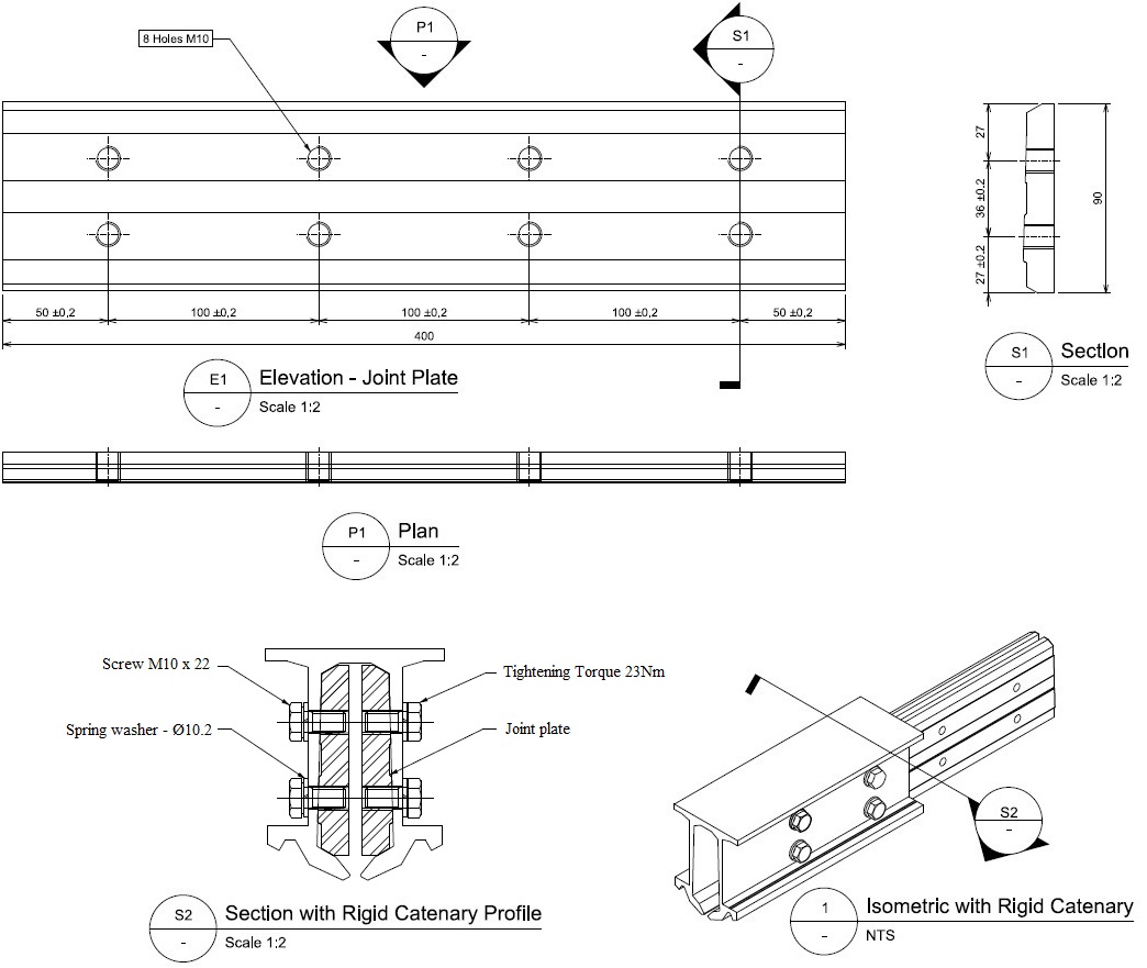
The rigid bar is 10m long with eight holes at each end to fix the joint plates for the bolted connection between two consecutive bars. The joint plates are made of the same alloy as the main bar (EN AW 6060 T6 EN 573-3) and the geometric shape of the plates fits the bar’s cavity and the aluminium profile bars are joined together to form a section by splicing bars that are greased and bolted until the bolt is fully inserted in the bar/threaded plate that connect the contiguous ends of the aluminium conductor profile. The tightening and splicing plates of two consecutive bars permit the electrical continuity and mechanical connection along the complete rigid catenary system. It is particularly important to centre and align perfectly the two consecutive bars before the tightening. Before assembly, the plates should receive a thin layer of contact grease on the contact areas.
The ramps are installed at the end of each section for making a mechanical overlap, insulated overlap and turnout. For example, the adjustment of the ramps in an overlap area is made in such a manner that the transfer of the pantograph from one ramp to the other is made on the straight parts of the ramps and not on the sloped part.
Each bar is cut to length based on the span (length between each support) the bar surpasses the support by 21% of the next span. The measurements of the span are already documented and allows for the cutting and drilling process to be achieved in the yard before delivery to site. On the occasion that a bar on site is the wrong length the ROC train consists of the equipment needed to cut and drill the bar to the correct length on site. The cutting machine is equipped with a cutting wheel for aluminium that is suitable for the size of the rigid bar. For greater accuracy, the drill must be a bench type column drill and the bits of suitable diameter. On average, sections are 450m long; however this length can be changed according to the configuration of the tunnel and approaches of stations.

Figure 8: Details of Joint Plate
Item Description Material Qty. 1 Rigid catenary profile Aluminium alloy 1 2 Spacer Stainless steel AISI 316 1 3 Screw M10x60 EN 5737 Stainless steel A4-70 1 4 Nut M10 EN 5588 Stainless steel A2 1 5 Spring washer Ø10.2 EN1751 Stainless steel A2 1 Figure 9: Details of Ramp
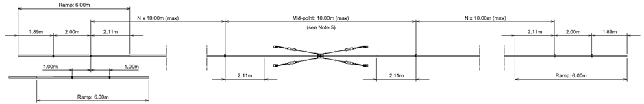
Figure 10: Typical ROC section length
A short section of ROC is used to allow for the overlap in the tunnel which then transitions out into the traditional system, that consists of two sections of overhead contact systems to smooth transition without affect to passenger trains. Each overlap consist of 4 supports and 2 ramped bars that also require equipment to anchor the catenary wire to allow for the flowing transition into the open route using and anchoring device that is used to withstand the tensional force due to the conventional (flexible) catenary. It is generally used at the starting and ending sections of rigid catenary to provide a fixed point. It is made of a stainless steel with four clamps fastened on it to lock the upper part of the aluminium profile.
Rigid Conductor adjustment mainly involves adjusting the height and stagger which is used for the transition of the contact wire radially from support to support to avoid over wear on the pantograph. Stagger on traditional overhead line system moved is a sharp ‘Zig Zag’ motion, however with a solid aluminium beam this sharp ‘Zig Zag’ motion is unachievable, and in the case of the ROC uses a sweeping motion to create longer bends whilst still achieving the same outcome of an evenly wearing pantograph.
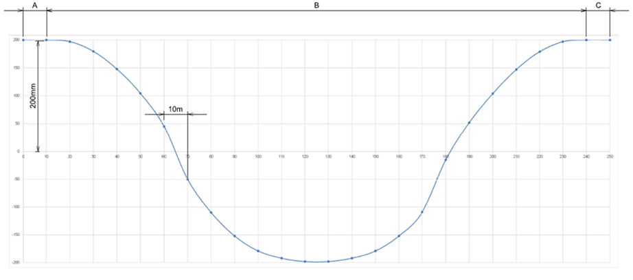
Figure 11: Example of stagger for a 250m section length
3.3 Contact wire
After a complete section of bar is installed this allows for insertion of the Contact Wire, this process requires a special railcar tool which allows for the profile of the aluminium bar to be opened then the contact wire to be inserted and the profile to be closed again. The bar aperture permits easy insertion of the contact wire while once the Contact Wire groove is clamped into the rigid beam, the tension force applied guarantees that it cannot be unclamped and no longitudinal sliding of the contact wire shall occur when submitted to traction (tests should be carried out for a traction load 10000N).
The contact wire is greased before installation in the rigid bar with a graphite grease or equivalent anti-galvanic grease for protection purpose against aluminium – copper galvanic corrosion. The minimum and nominal contact wire height is 4.25m in all tunnel sections as per EN 50122-1.
3.4 Mid Point Anchors and Electrical connections
The full section of bars requires a mid-point anchor which stops the bar from moving longitudinally these are installed roughly in the middle of the section. A mid-point anchoring arrangement must be installed at the mid-distance between the two ends of the section length as specified by the design document. This operation may be performed during the installation of the rigid overhead conductor bar / beam or after the contact wire has been inserted as it is not used during contact wire insertion. It is preferable to hold the rigid bar in position with a temporary sling during unwinding to prevent the assemblies being pulled out.

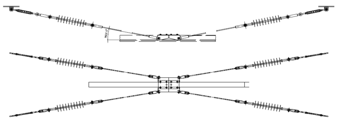
Figure 12: Heavy duty Mid-point arrangement using four anchor insulators
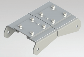
Figure 13: Heavy duty Mid-point anchor plate
MAIN CHARACTERISTICS Element Material Section ROC Bar Extruded aluminium alloy EN AW6060 T6 N/A Height: 110 mm N/A Weight: 5.96 Kg/m N/A Contact wire Solid grooved copper 150mm2 Joint Plate Aluminium alloy (EN AW 6060 T6 EN 573-3) N/A Insulators Polymeric N/A Aerial Earth Wire Atranded ACSR 93mm2 Figure 14: Main Characteristics of the different elements
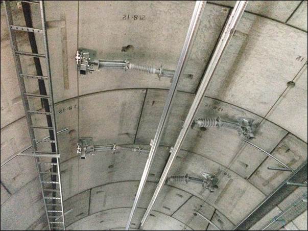
Figure 15: Photograph of ROC Installation in the tunnels
4 Engineering trains
Multiple engineering trains have been designed and imported to Crossrail for the installation of the Rigid Overhead Catenary. The most relevant trains used are described below:
4.1 RSM6: Self-Propelled Platform
RSM6 is the train headcode to identify the vehicles that have been designed to facilitate the work on the overhead chain and the equipment connected to it that can be installed even at very elevated heights in relation to the track surface. The use of this train permit to considerably increase the efficiency of the works, in accordance with the health and safety standards to protect the operating personnel. Two ALSTOM self-propelled platforms have been imported to C610 OHLE.
Gauge 1435 mm 
Wheelbase 3000 mm Mono-block wheel diameter 600 mm Axles 2 unit Length 6340 mm Width 2500 mm Max height (for transport) 2550 mm Working platform dimension 3000 x 1600 mm Weight capacity for platform 300 kg Working platform rotation +90º G Max useful height (for working) 7000 mm Max lateral distance (90º rotation) 4000 mm Max working speed for platform 9 km/h Max transfer speed 18 km/h Max speed towed 55 km/h Figure 16: RSM6 Self-propelled platform technical specifications and photograph
The main advantages of this vehicle are represented by:
- High speed towed reduces travelling time and extra labour.
- Working platform height, dimensions and rotation to work comfortably and safely.
- A dual electric and diesel thrust system.
- Lighting system for tunnel works which illuminates the area around the machine.
- Closed containers of the accessible platform for equipment.
- Very efficient engine case which reduces noise pollution during operation and transfer.
- A metal frame designed to support the vehicle´s insertion in a goods train and support the stresses due to the use of the load transported in the work trolley.
- A suspension system capable of absorbing impacts with the track and which guarantees the safe straight line movement as well as around bends.
4.2 OH2: ROC train
A specific train has been constructed for the storage, preparation and installation of rigid bars. Due to the dimensions and weight of the aluminium ROC bars, elevating platforms are not suitable for the installation of this equipment. OH2 train is formed by a traction unit (locomotive or similar), a working platform wagon, a workshop gantry wagon and a welfare unit. 2x RSM6 and CBF2 wiring unit are towed in different configurations to this train. Two double-wagons have been used to build the working and the workshop gantry platforms:

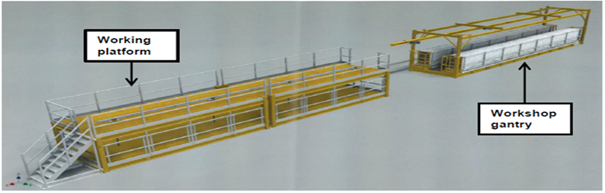
Figure 17: Detail of OH2 double wagon and workshop gantry platforms
Enhancement of Health and Safety of workers:
- Harness is not required for operatives in the working platform, as it is fully surrounded by tested and approved handrails.
- Reduce the need for manual handling.
- Eliminate risks of carrying heavy loads.
- Ladders and elevating platforms eliminated in the ROC rail bars preparation and installation.
- Better working position.
- Welfare facilities available at all times.
Quality assurance:
- A quick and efficient method for installing OHLE equipment in tunnel.
- Timesaving and labour saving solutions.
- Safe storage and work on the same wagon.
Improving progress rates:
- Independent working wagons to keep a “production line” of preparation and drilling of rigid bars and installation at the same time, making possible an installation rate of 50 meters per hour (500 m per shift).
- Elevating platforms and drum carriers towed directly to engineering trains eliminate the use of MEWPs and RRVs, improving the speed and logistics of accessing to the different locations of the tunnel.
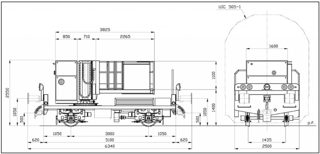
4.3 CBF2: Unwinding unit
CBF2 drum carrier has been brought to C610 Crossrail project for the unwinding of the contact wire that will be inserted inside the ROC rail bar, forming part of OH2 train. However, as a self-propelled unit, it can work independently and can be used with other purposes, such as Aerial Earth Wire installation (OH1), achieving rates up to 1800m per day.

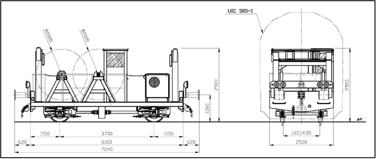
Gauge 1435 mm Wheelbase 3700 mm Mono-block wheel diameter 600 mm Motorized axles 2 unit Length 7240 mm Width 2500 mm Height of loading floor 800 mm Max speed in winding condition 5 km/h Max speed in working condition 10 km/h Max speed towed 55 km/h Max tensile stretch for each reel 800 daN Capacity of each metal reel 3000 kg Figure 18: CBF2 unwinding unit technical specifications
Main features and advantages of CBF2 are as follows:
- Three speed conditions: CBF2 possesses an efficient transmission system which allows the winding movements at a sustained and reduced speed. As it can be coupled to the working train, the delivery can be done at a train speed (55 km/h), maximizing the working time.
- Reversible: CBF2 can operate in both directions, facilitating the train configuration and working conditions.
- CBF2 is designed to cope with stresses and has a suspension system to absorb impacts with the track, guaranteeing a safe movement.
- Two independent reels, formed by steel supports and drum carriers capable to carry 3000 kg each.
- Illumination system in tunnel in both sides of the machine to notice its presence and working conditions.
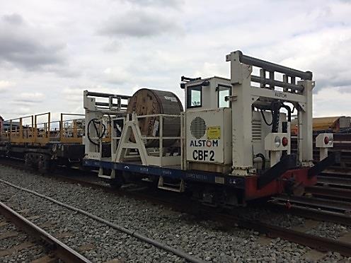
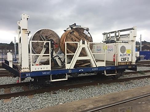
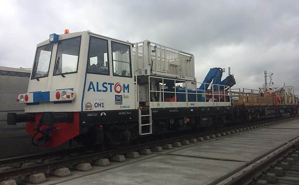
Figure 19: CBF2 photographs
5 Conclusions
The development of the ROC system has reduced the maintenance requirements and construction cost compared with the traditional systems. In the Crossrail project the main areas of improvement have been the following:
Mid Points design: The midpoint anchor installation requires the drilling and installation of four anchor plates and the preparation of the stay back cables that connect it to the central plate. The complexity of this design can cause potential delays in the installation of this equipment where the average rate is 2 units per shift. A fixed anchor point is used in different Rigid Overhead systems as mid point anchor, further study is required to investigate if a fixed anchor can comply with Crossrail rigid bar loads.
Bars manufacture: a drop tube as-built is required following the installation of the supports and cantilevers to measure the span between consecutive supports and to calculate the length of every ROC bar, which needs to be drilled and cut. An efficient planning to record all these measures and produce a rigid bar register is beneficial to get the bars prepared in the yard maximizing the installation time on site; otherwise there is a risk to spend too much time in the workshop wagon, cutting and drilling the bars on site.
Rail Operations: One of the biggest challenges in the Systemwide contract is the Rail Operations planning. More than sixty Rail Vehicles are accessing the trace on a daily basis, including Road Rail Vehicles (RRVs) and Trains departing from Plumstead Railhead. A detailed coordination is required between the different Systemwide teams for each section of the trace. The arrangements have been applied to the planning and booking of the works following the Construction and Commissioning Rule Book (CCRRB), through the management of Four Weekly, T-1 Weekly and Daily Notice meetings to ensure project priorities are safely achieved. Analysing the train timetable in the Railhead and the location and number of access points for MEWPS and RRVs is critical for effective logistics implementation, optimizing time on site and ensuring safety of the personnel working within the trace.
Resources: The installation of the aluminium profile and the contact wire requires adequate dimensions, tools, plant and equipment. Modifications have been carried out to improve the efficiency of the extraction vacuum system of the Tunnel Drilling Rig. The machine has completed the execution of the drills having achieved excellent production rates combined with high levels of accuracy and mitigating the risks during the drilling operations. Furthermore, the Engineering Trains used by the OHLE team have allowed maximising the procedures for the installation of the ROC system, facilitating the logistics and work methodology within the tunnels.
Procedures: Significant improvements have been achieved since the beginning of the ROC installation due to the expertise of teams and optimization of work procedures. Progress rates have increased from 200 m/shift reaching quantities up to 800 m/shift of rigid bars. Installation rates of Aerial Contact Wire have improved from 400 m/shift up to 1800 m/shift. A previous height and stagger adjustment is required to install the bars in tolerance and minimize the final adjustment once the ROC is installed.
The combination of a detailed in advance planning with the adequate plant and resources in place, have allowed the C610 team to implement an effective sequence of works to complete the installation of the ROC in zones 1 and 2 of the Crossrail Central Operating Section, with more than 30 Km of tunnels ready for Energisation as a precursor to Dynamic Testing.
6 Appendices
Appendix 1: Summary of C610 OHLE and Traction E&B equipment
C610 OHLE and Traction E&B equipment Sub-system Component ROC (tunnel) Rigid bar Joint Plate Anchoring device Blocking hanger clamp for mid-point Hanger clamp Transition Bar Drop tube Insulators Anchor bolts Rigid bar clamp Cantilever Aerial Earth Wire Contact wire Protective cover OCS (surface) Masts Stayed beam Portal structures Insulated cantilevers Tensioning device Section Insulators Neutral section Anchor insulator Contact wire Droppers Aerial Earth Wire Electrical connections Traction earthing and bonding Earth bar Traction earth wire Earthing connections Return current cables OHLE cables Negative feeder / Track feeder / Sectioning cables 7 References
[1] Mak, M.K. (2014). Adoption of Overhead Rigid Conductor Rail System in MTR Extensions. Journal of International Council on Electrical Engineering, 2:4, 463-466 – Taylor and Francis Group, LLC
[2] Melis Maynar, M and Gonzalez F., F.J. (2008). Ferrocarriles Metropolitanos. 472-478. Colegio de Ingenieros de Caminos, Canales y Puertos (Spain).
[3] Wane, S. (2017). Installation of Rigid Overhead Conductor system (including cantilevers and contact wire) in Crossrail Tunnels. CRL Document Number: C610-ATC-O1-GMS-CRG03-50169. Crossrail Limited.
[4] Ruegg, R. (2015). Semi-Automated Tunnel Drilling Machine – Operations and Maintenance Manual. CRL Document Number: C610-ATC-C-GML-CRG03-50001. Crossrail Limited.
[5] Carr, Colin. Developing ROCS for the UK. (2016). Rail Engineer. issue 140.
[6] Use and maintenance manual RSM 6-DE
[7] Use and maintenance manual CBF2
-
Authors

Alfred Satchell - Crossrail Ltd
OHLE Site Engineer
Javier Zamorano MEng - ATC
OHLE Construction Engineer