Maintenance and Cost Analysis on Major Subsurface Rail Projects – Crossrail
Document
type: Technical Paper
Author:
Richard Consterdine MIMechE MIAM, Jonathan King FIET, ICE Publishing
Publication
Date: 09/07/2018
-
Read the full document
1 Maintenance Development
1.1 Maintenance Overview
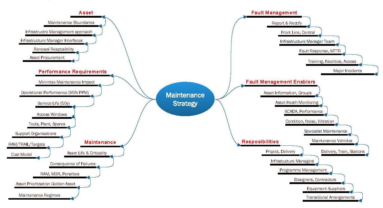
As the project is a new infrastructure project the early thinking was to promote an integrated maintenance strategy (IMS). The aim was to develop an integrated and optimised cost maintenance regime. The IMS was founded on the principle of minimising maintenance and mitigating maintenance issues by influencing the design of infrastructure during design and construction. To develop this concept, a maintenance strategy had to be developed. This considered items such as allocation of assets between the Infrastructure Managers (IM), how targets for the reliability, availability, maintainability, and safety (RAMS) were achieved through incorporation of maintenance requirements into the design. The strategy had to cover a vast amount of information for its initial development, which is illustrated in figure 1.

Figure 1 – Maintenance Strategy
The maintenance strategy was accompanied with a high level suite of information. These are shown in figure 2, and illustrate the information flow between them. These inform the operators, IM, design teams, and satisfy the crossrail project functional requirements (CPFR). The documentation would set out how the maintenance would be delivered across the entire programme. Notwithstanding this, the paper will firstly cover the maintenance strategy concepts, which allowed the project to progress.
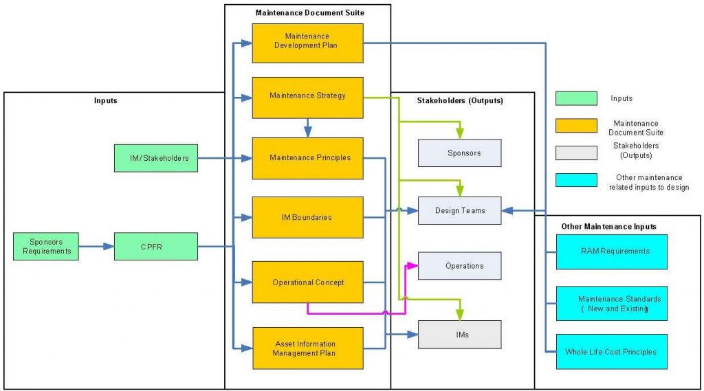
Figure 2 – Maintenance Documentation
1.2 Maintenance Strategy
1.2.1 Asset Consideration
Asset ownership had to be agreed between the sponsors i.e. Network Rail (NR), London Underground (LU), and Rail for London (RfL), so it was clear who was responsible for maintenance and renewals. A lot of this was straight forward, however where it was not, principles such as not changing ownership along a system, and who was most impacted by its performance were used to agree this.
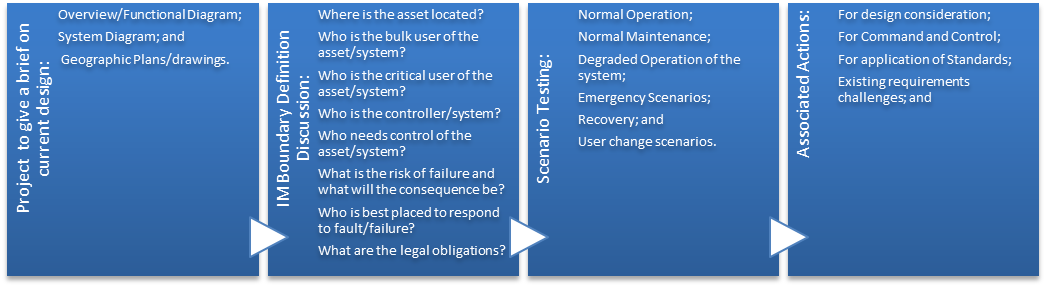
The optimum maintenance boundaries had to be found to detail assets within it and the interface with other locations and systems. A level approach was adopted to define boundaries i.e. Level 1 – Rail Systems, Tunnels between stations or Station (e.g. Bond Street Station); Level 2 – At asset level (e.g. signalling) and Level 3 – Detailed interface level (e.g. IM for the fixing bolts, cables ends etc). The process of the developing IM boundaries for the systems is shown in figure 3.

Figure 3 – IM Boundary Analysis Process
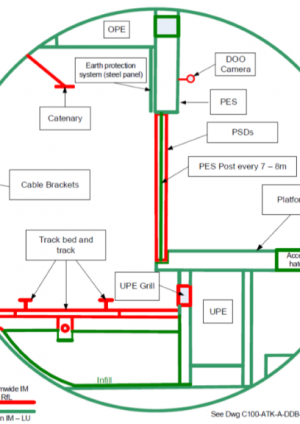
A typical interface boundary at in a subsurface station at level 1 can be seen figure 4, along with a typical completed template for overhead line equipment in a station at level 3;
External maintenance Interfaces had to be understood by the IM such as major developers, airport authorities, national power/grids, train/freight operating companies and over site developments.
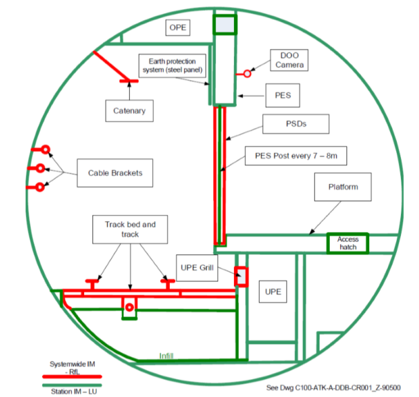
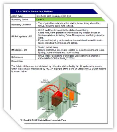
Figure 4 – IM Boundary Formations
The infrastructure has an impact on the performance of the railway and renewals possess a number of challenges. Therefore it was necessary to consider renewals during design, and was assessed as design progressed i.e. possession length, station availability, etc. CPFR specified a limited number of 52 hour possessions per year and night time engineering hours when this work could be undertaken.
The use of standardised equipment was preferred for efficient maintenance, but care was needed not to rely on single source suppliers. Standard components were used where programme procurement strategy would allow, and assets were procured to optimise characteristics as shown in figure 5. Some supplier frameworks were sort for equipment such as; uninterruptable power systems (UPS), building management systems (BMS), digital addressable lighting interface (DALI), and lifts and escalators. (For further understanding on common design and common components see technical paper [1]).
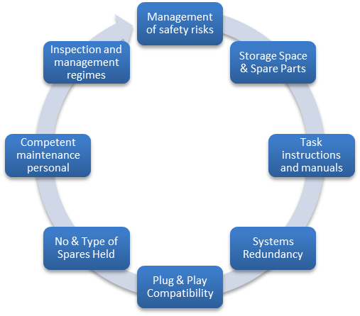
Figure 5 – Standard Component Optimisation Characteristics
Training requirements needed to be planned for the additional assets, systems, or solutions that are novel to the relevant IM. The IM also needed to understand if its workforce needed to be upskilled. The definitive maintenance practice was developed once the detailed design was finally evaluated, which determined the overall training requirements. Initial training (‘train the trainers’) for assets were also considered and provided.
1.2.2 Performance Requirements
Service patterns and time tables needed to be understood along with stabling and moving roiling stock ready for service or end of service. The access time windows needed to be analysed with the last and first trains, along with opening and closing times of the stations, so designers could accommodate requirements in their design. They also needed to follow a sequential approach, illustrated in figure 6.
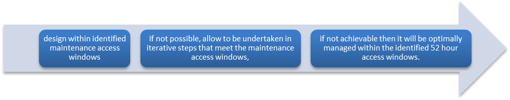
Figure 6 – Sequential Design Approach to Access Windows
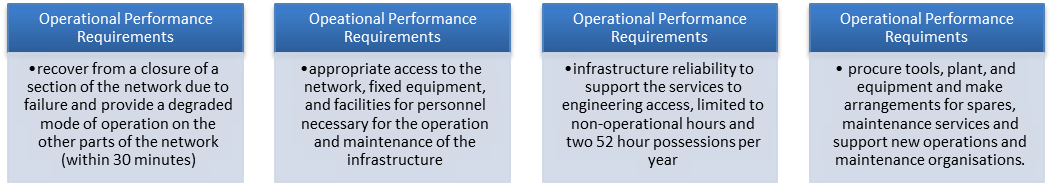
The early project operational performance requirements were generated from the CPFR and needed to be integrated into the forthcoming maintenance regimes and design of the infrastructure. One of the main considerations was the life span set at 50years for key systems with no drop off in performance. Some of the other early operational requirements which maintenance had to consider, are as shown in figure 7.
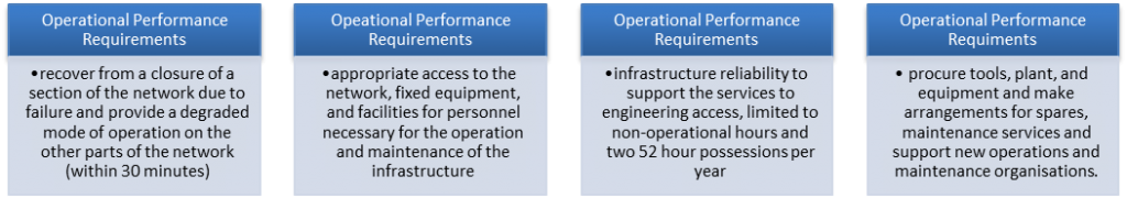
Figure 7 – Early Project Operational Requirements for Maintenance
The maintenance also had to be integrated with the reliability allocation on systems especially for the mean time before failure (MTBF) and mean time to repair (MTTR). Alongside this dynamic simulations needed to be undertaken. Transport Reliability Availability Infrastructure Logistics (TRAIL) simulation software and its modelling via NR were undertaken and its analysis provided assurance that 95% Passenger Performance Measure (PPM) could be achieved. This also confirmed the RAM values that systems had to achieve. Simulations also proved that infrastructure and rolling stock schedule can cope with specific operational scenarios. (For more information on project RAMS see reference [2]).
1.2.3 Maintenance
The nominal asset life for each main asset groups needed to be considered in design, with a varied approach to maintenance and management of assets with differing design lives, such as civils, communications, electrical etc. Novel assets such as the rigid overhead catenary and signalling needed to be further investigated. The overall approach for asset criticality was to take account of the following;
- The probability of failures;
- The losses and consequences of failure; and
- Associated maintenance, inspection, and reactive maintenance costs.
However, notwithstanding this, a very early assessment of asset prioritisation was undertaken on critical or ‘golden’ assets and systems. The high critical assets are shown in Figure 8, and further identification was required throughout the design development, which resulted in reduction.
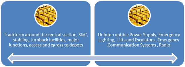
Figure 8 – Golden Asset Identification
The maintenance strategies for the prioritised management of assets, is shown in figure 9. This shows the high criticality assets, medium criticality assets and low criticality assets. Assets which are unique to the new crossrail infrastructure are treated as high criticality assets. The full quantitative assessment of maintenance, are described below[1], from figure 9.
- FMEA – Failure Modes and Effects Analysis – to identify all risks inherent in the operation of the assets;
- RBTA – Rule-Based Task Allocation – to identify the most appropriate tasks for mitigating or preventing failure mode risks according to a consistent logic based on an analysis of asset deterioration;
- CRO – Cost-Risk Optimisation – to set the optimum frequency or interval for carrying out the tasks identified in the RBTA. Achieves this by quantitative analysis of the costs and risks inherent in undertaking the task;
- Maintenance Justification – that presents the reliability, safety, and economic case for adopting a specific optimised regime. Will address all regulatory impacts of the optimised regime;
- Standard Maintenance Specification – standard risk-based maintenance specification that will be carried out across the relevant assets by the relevant Infrastructure Maintainer;
- Risk-based Implementation – implementation of the optimised regime according to the risk profile of the asset base, varying frequencies and tasks according to risk.
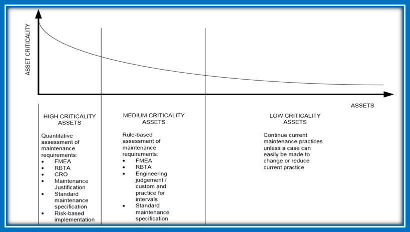
Figure 9 Asset Criticality
1.2.4 Maintenance Regimes
The infrastructure needed to be designed and maintained within the constraints usually found in an underground metro railway environment along with limitations around possession time. A criticality-based approach was initially proposed to determine the frequency and type of intervention. These intervention intervals and tasks will (with automated data collection system), be determined dynamically based on data recorded. In other, less critical cases, it was still be necessary to consider the planned intervention and maintenance to ensure that an incremental impact on infrastructure availability is not allowed to build up.
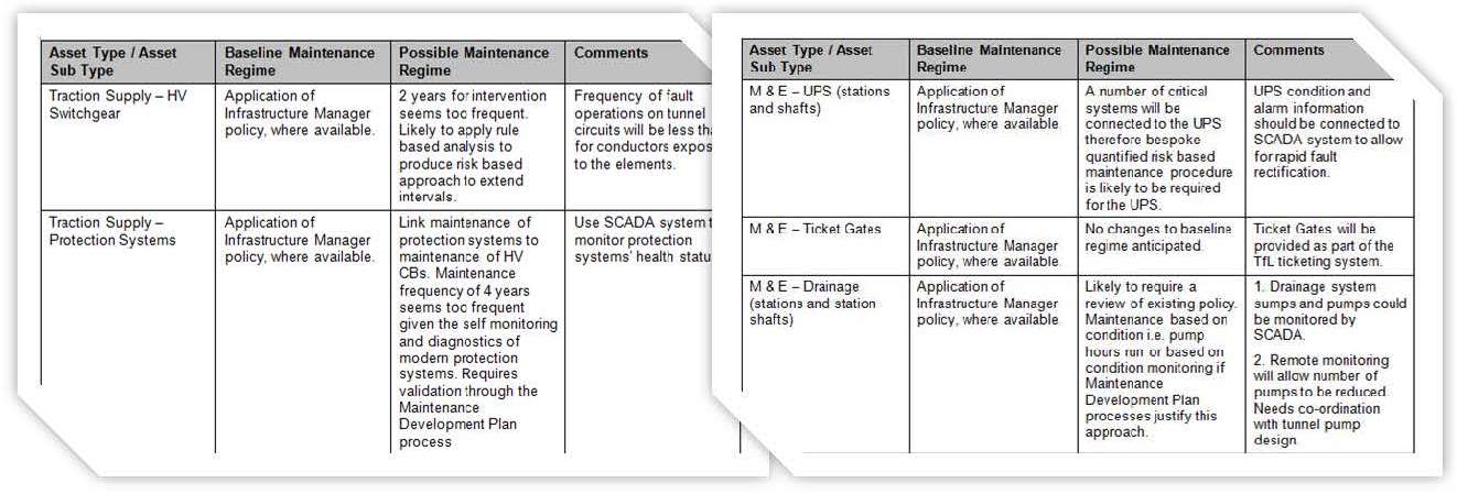
A small number of asset groups can consume a large proportion of maintenance hours, and for railway systems are track form and overhead line electrification (OLE) and, and for stations, shafts and portals (SSP) are lifts, escalators (L&E), and mechanical and electrical systems (M&P). NR or LU maintenance standards were specified, along with any statutory requirements, for the initial maintenance regimes. RfL was a new organisation and had no unique standards to follow. The approach to the maintenance regime in the initial maintenance strategy can be seen in figure 10, with a typical regime provided in figure 11 for traction supply equipment and UPS ticket gates and drainage at SSP.
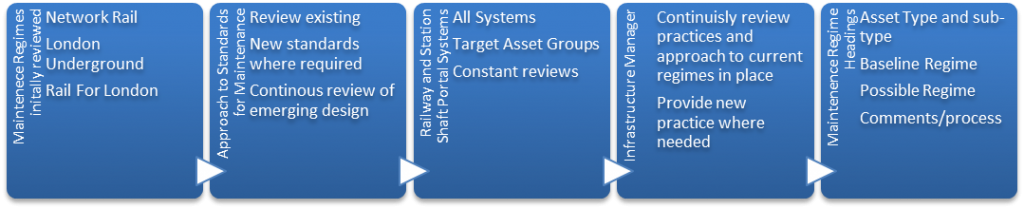
Figure 10 Maintenance Regime Approach
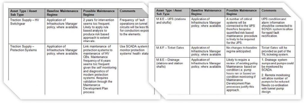
Figure 11 Typical Initial Maintenance Regimes
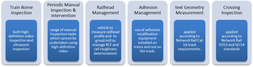
Track form was reviewed by a working group at a functional level. Its regime was tabulated using an initial and steady stage approach, and the general principles underlying this strategy are the following, with more detail provided in figure 12.
- Risk based – addressing critical issues and failure modes associated with gradients and curves;
- Information based – ensuring asset information drives optimum tasks and frequencies for inspection and periodic replacement, which are calculated using pessimistic assumptions;
- Automation based – maximise use of automation for condition monitoring and data collection;
- Rail focussed – ensuring RCF, wear, and noise and vibration are managed holistically;
- Separation – as far as possible avoiding the need for staff working on the track.

Figure 12 Initial Maintenance Regime Approach for Track work
1.2.5 Fault Management
To ensure targets for high availability of the railway were met, the project promoted a proactive approach to maintenance to mitigate failures through targeted/risk-based interventions and use of intelligent infrastructure. Quick response is essential to maintaining availability of infrastructure and response can be ensured by placement of front line response teams at central locations. Crossrail provided welfare facilities at all locations to assist the IMs in locating response staff. An assumed average incident response time was subsequently used in TRAIL modelling and communicated to the crossrail suppliers so they could calculate MTTR as part of their RAM analysis.
The initial strategy looked at the typical journey times to reach locations, such as using public transport and the crossrail network. However, the IM had to decide where optimum locations for the first response and any cross boundary support to optimise fault response. Stepney green will be a key base for the RfL emergency response managers as it is located above the vital and non-redundant points that direct trains to the south east or north east branches.
1.2.6 Maintenance & Fault Management Enablers
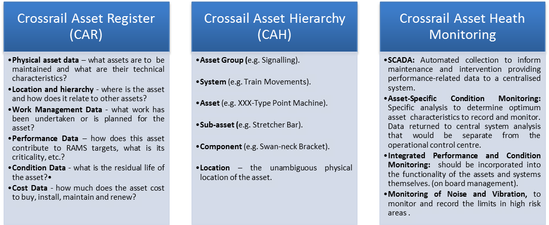
Fundamental to the identification and demarcation of assets was the concept for the development of the crossrail asset register (CAR), and the understanding the idea asset hierarchy. Asset heath monitoring also needed to be planned as a significant amount of the planned intervention time is concerned with inspection and condition assessment. These concepts proposed are shown in figure 13.

Figure 13 Asset Register, Hierarchy and Heath monitoring concepts
Specialist rolling stock, plant and equipment to support inspection, maintenance and renewals needed to be understood, detailed and provided by the IM. Some station assets such as high voltage (HV) transformers have to be replaced by train. The limited engineering access time is anticipated to drive a requirement for significant automation of maintenance and inspection tasks. As a result, a range of specialist rolling stock, plant and equipment was envisaged. The project assumed any such a vehicle should provide bespoke functionality, such as
- Ability to maintain and replace wearing components within the overhead system;
- Ability to maintain and replace the rail system;
- Ability to transport maintenance staff throughout the railway and, in the Central Section, load/unload them directly to the raised walkway; and;
- Ability to transport consumables and strategic spares and load/unload them directly to/from access points within the Central Section.
The project also had to facilitate for transitional arrangements. This included the maintenance of completed, installed and commissioned infrastructure prior to the commencement of operational railway.
1.2.7 Responsibilities
A responsibilities matrix needed to be provided for the project which defines the responsibilities for the various key maintenance strategy activities. This was undertaken in the NR format i.e. by using a RACI (Responsible, Accountable, Consulted, and Informed). The responsibilities can be seen in table 1.
Table 1 Responsibilities for Key Maintenance Activities
Activity Project Project Partners Designer IM IM IM Equipment Suppliers Set Maintenance Strategy A/R C C C Asset and System Information A R C C C C Asset and System Boundaries A/R I I C C C Asset and System Prioritisation A/R I I C C C Maintenance Interface Identification and Management A I I R R R Production of Maintenance Appendix of CDS C A R C C C Development of Detailed Maintenance Procedures and Periodicities C A R C C C R Optimised Maintenance Costs A R R C C C C Procurement of Maintenance Plant and Equipment A/R C C C C C Delivery of initial maintenance training where required A C C I I I R Transition Management and Planning A R C C C Renewals Strategy (On-Networks) C A/R I I Renewals Strategy (Tunnels – Rail Systems) C A/R I I Renewals Strategy (Station Systems) C I A/R A/R 2 Management of Maintenance Delivery
2.1 Overview
Maintenance has been developed jointly between crossrail and the IM over the project lifecycle so that the railway is progressively deemed suitable and maintainable by the IM prior to handover. A four weekly maintenance steering group meeting is also held and attended by the IM maintenance representatives and is chaired by the crossrail maintenance planning engineer. These have guided maintainability of assets being delivered by the project. A key output of the crossrail maintenance steering group is the running of circa 60 or so maintenance integration review panels (MIRPs).
2.2 The Maintenance Integration Review Panel (MIRP)
The MIRP workshops reviewed all assets during the final design development stages, where the IM was more engaged and integrated within the project. These were gate 2 gate 3 stages, and in terms of maintenance, called MIRP 1 and MIRP 2 respectively. The aim of the workshops is to check that there is an integrated design and that the assets are maintainable individually and that the railway as a whole is maintainable. The panel consist of crossrail maintenance staff, crossrail suppliers, and IM. Actions agreed have fed into design changes, identified scope gaps and led to improvements in the maintenance documentation.
The MIRP workshops have also considered a number of maintenance scenarios suggested by RfL, so that crossrail could demonstrate that the assets are maintainable and address RfL areas of interest or concern. Where issues have been picked up with these scenarios, these have been noted as actions to close out.
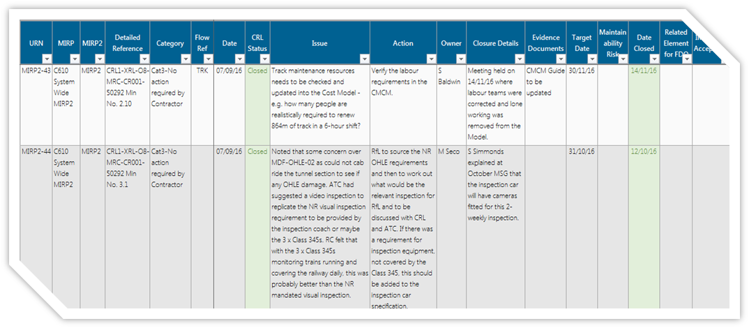
A holistic maintenance plan and maintainability assessment statements were produced for each system and this documents key findings from the MIRP workshops and actions to address. Actions raised at MIRP workshops are contained in the action tracker which is regularly updated as closure evidence is gathered by the crossrail maintenance planning engineer. The actions are then presented to the IM for their acceptance. An example of the MIRP tracker is shown in figure 14, illustrating the how the tracker helps manage the maintenance integration with the IM and to close out the important issues during the final maintenance agreements and developments.
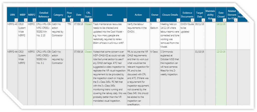
Figure 14 – Example MIRP Action Tracker
Confirmation that the railway was maintainable and that there was sufficient access to undertake this work was covered by the maintenance elements as shown in figure 15. By undertaking the key maintenance elements, it concluded that the maintenance fits into the nominal access times, that there is sufficient access to maintain the railway systems and SSP systems and that assets can be maintained within the allowable 52 hr shutdown periods.
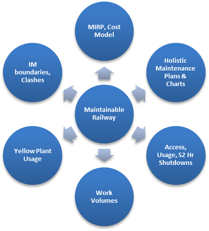
Figure 15 – Key Maintenance Delivery Elements
3 Failure and Maintenance Analysis
3.1 Overview
Crossrail is designed to meet the RAMS performance requirements set by the TRAIL model. These are set in terms of system reliability, availability, and maintainability and repair times. For the project, the supply chain had to demonstrate that their design will meet the RAMS requirements for each system. To demonstrate this, they had to consider the effect of potential failures of systems, corrective and preventive maintenance times and redundancies built into the design. The RAMS was also expected to comply with BS EN 50126:1999.
3.2 Failure and Maintenance analysis process
To satisfy the above, suppliers submitted maintenance and failure analysis data forms for each asset or system for its failure and maintenance characteristics. The project provided guide forms, one for “failure analysis”, and two for “Maintenance analysis.” Finally, to demonstrate that the railway and SSP systems could be accessible and maintainable, suppliers delivered an access and maintenance strategy.
3.2.1 Failure Analysis
The intent of the questions on the “failure data form” were to identify potential failures for equipment or the system and identify if failures could result in train impacts, station disruption, affect safety of crossrail or environmental. The questions can be seen in figure 16.
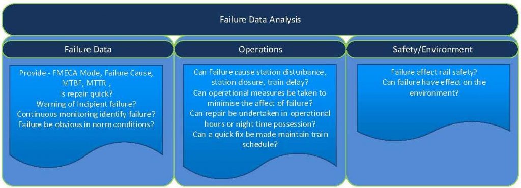
Figure 16 – Failure Analysis
The questions target line-wide replaceable units (LRU) and reliability criticality list (RCI), as well as failure mode effects criticality analysis (FMECA). Then the form interrogates system on failure characteristics, warnings, etc and for operations and safety/environment.
3.2.2 Maintenance Analysis
The main intent of these questions was to identify maintenance requirements and maintenance information for equipment, systems and subsystems. This was also to try and reduce any stations or line-wide operations and or safety of the central section. This firstly started with the “Maintenance data form”, as shown in figure 17. This requires the supplier to provide monitoring, preventative maintenance data, including testing, on all equipment.
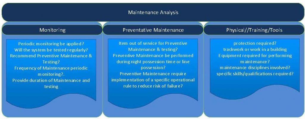
Figure 17 – Maintenance Analysis
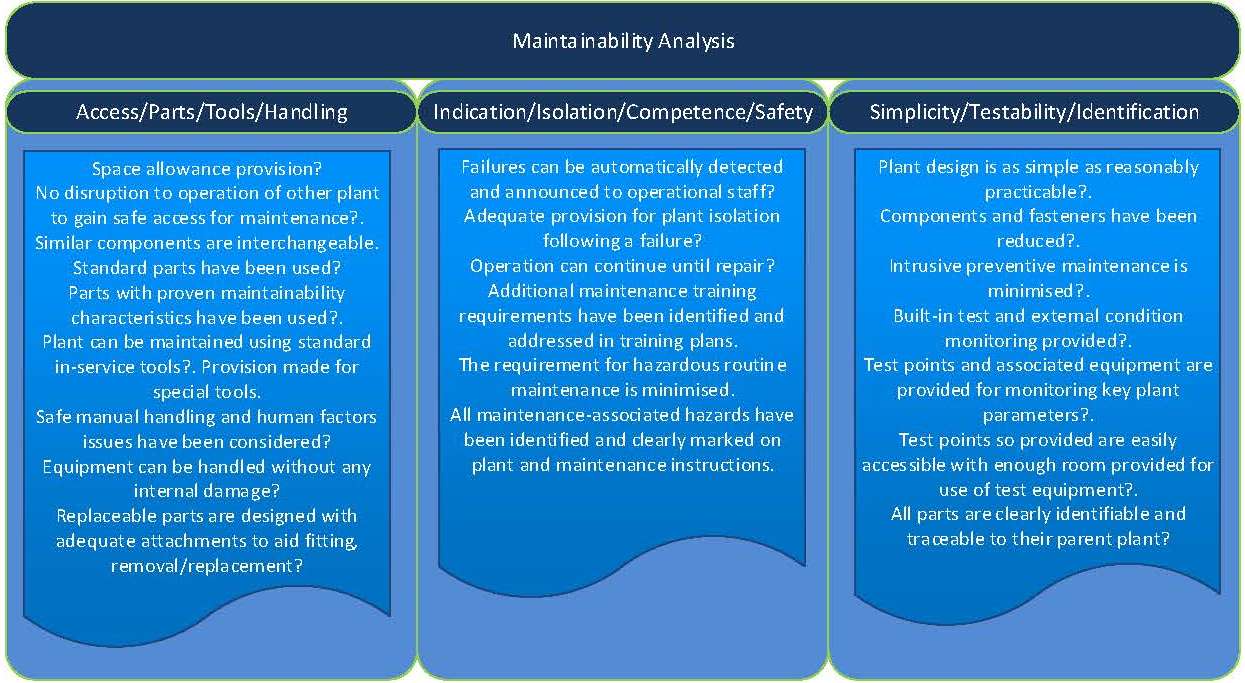
The second part of the maintenance analysis is provided in the “maintainability check list data form”, and this required the suppliers to provide evidence that maintainability has been considered and optimised for during design. Questions were designed to ensure that the design had also taken suitable measures that the maintenance of the systems can be undertaken reasonably. This is shown in figure 18.

Figure 18 – Maintainability Analysis
The information from the failure and maintenance analysis was used to inform the costing model, maintenance, project assurance, and compliance. This is both for the crossrail and the IM and can be seen in figure 19.

Figure 19 – Maintenance and Failure Analysis Outputs
3.2.3 Access and Maintenance (A&M)
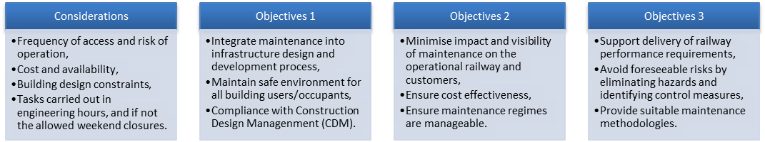
The suppliers, to deliver A&M, needed to consider design life i.e. 120 years, and replacement of mechanical and electrical systems during this period. Suppliers had to provide the mechanical, electrical, civil, structural, and architectural elements and systems at the SSP and each railway system i.e. tunnel ventilation, platform screen doors, track, and overhead line. The typical considerations and objectives can be seen in figure 20.
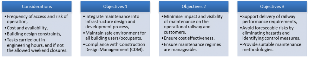
Figure 20 – Considerations and Objectives of A&M Strategy
Installation and maintenance routes and methods needed provided, sized, and designed to accommodate the equipment characteristics (i.e. size, weight) from the location to their external delivery/removal point. This included provision off hatches, lifting, cleaning apparatus, and permeant and temporary equipment to aid the safe maintenance process of the systems. Some of these are illustrated in figures, 21, and 22 respectively.
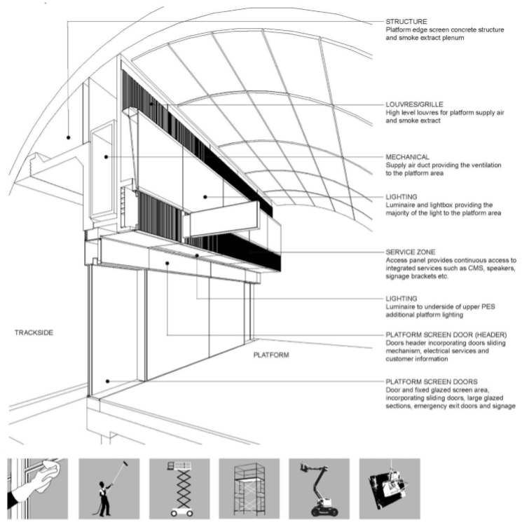
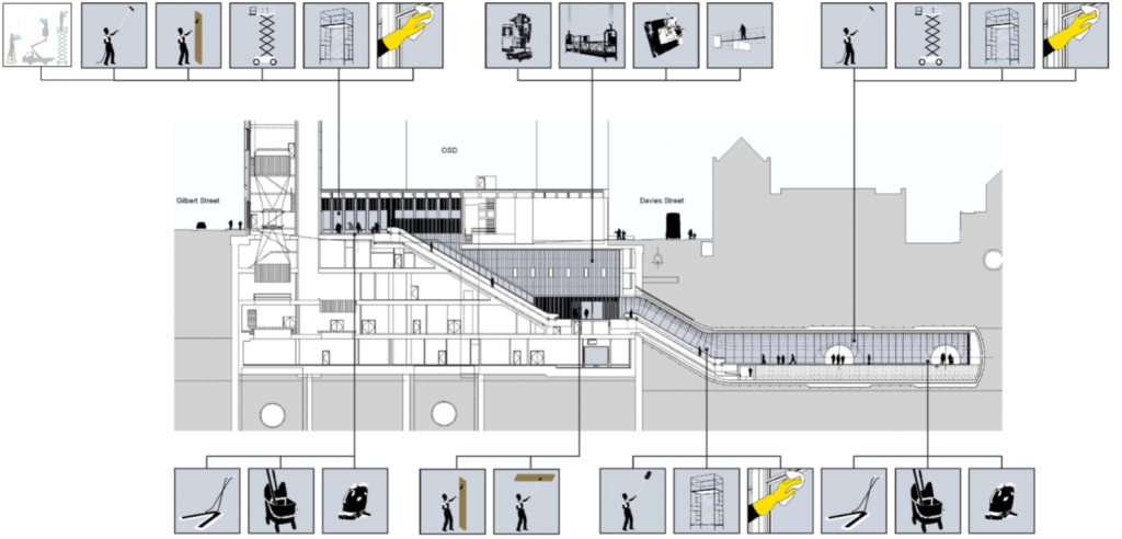
Figure 21 – Typical Station A&M Considerations

Figure 22 – Typical Station A&M Consideration
4 Cost Analysis
4.1 Overview
The cost modelling undertaken for maintenance has considered maintenance and operations, and together with performance modelling are predominantly, in three elements;
- TRAIL modelling of the infrastructure and proposed timetable (by NR);
- Inspection, maintenance and renewal cost and maintainability modelling of the proposed designs with the crossrail maintenance cost model (CMCM), (by crossrail project)
- Financial, contractual and affordability cost modelling with operations, maintenance and renewals budget (OMR). (Note: This proposed budget would be undertaken with the nominated operators, and the current project delivery RAM team is not involved with this).
The models and budgets have a close association, since many of the key stakeholders in the operation of the finished railway have a specific interest in at least two of the three. The linkages between design, performance, maintainability, resource levels, costs, and affordability are many and it is essential that these models were consistent in their assumptions and their interactions with each other. The models and budget inputs and outputs can be seen in figure 23.
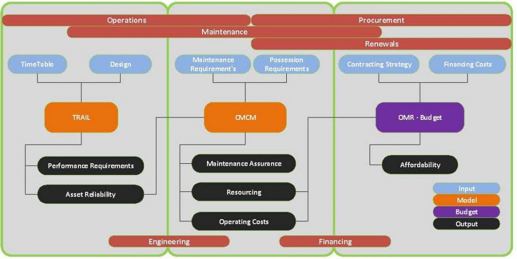
Figure 23 – Costs Models
This process allows the models to provide assurance across the entire spectrum of performance, maintainability and affordability, where;
- The TRAIL performance modelling provides input into the design assurance and operational capability assurance elements, as well as enabling performance to be confirmed;
- The CMCM uses similar information on the design of the infrastructure (including stations) as well as some of the outputs of TRAIL to determine work volumes, resource levels and associated costs for the inspection, maintenance and renewal of the infrastructure;
- The outputs of the CMCM can be used to feed the OMR budget, which can bring in estimates for the procurement and information regarding contracting strategies and financing methods to provide overall affordability assurance.
4.2 Whole Life Costing (WLC)
The project is committed to delivering a world class affordable railway, whose life will extend for 120 years beyond construction and recognises that the initial capital cost, while considerable, is only part of the total cost of the project. Considering the balance of capital cost and WLC, the project approach is to first ensure compliance to minimise the final cost and ensure that the final direct costs do not exceed the total sponsor committed funding. Within these limits, the project can consider WLC to optimise WLC on the basis of an appraisal period of 50 years. The project WLC policy is;
- Evaluate, design and specify options against a baseline position of normal industry practice as defined by the standards baseline;
- Apply a standard methodology for the appraisal of WLC, aligned with the project investment model and economic appraisal;
- Maintain a programme wide perspective to ensure that localised changes continue to support the delivery of the overall system performance;
- For options that require a material increase in initial cost or a change in funding, in order to optimize WLC seek authority to change from the baseline position through the change procedure;
Station cladding for the spray lined concrete platform tunnels is a good example of where various options were examined, based on seven criteria, with glass fibre reinforced concrete (GFRC) being eventually chosen, as shown in figure 24.

Figure 24 – WLC for GFRC
Value engineering has been used when programme and cost issues have arisen. General station cooling was eliminated to save costs, but the space was kept for it, so it could be installed at a later date as passenger numbers and the climate demanded it. An escalator was removed at Farringdon station eastern ticket hall, replaced by an inclined lift, so reducing the need for a separate lift shaft in a complex area with poor ground conditions. Numerous smaller value engineering changes and decisions have been made.
4.3 Crossrail Maintenance Cost Model (CMCM)
CMCM models the asset register against predefined behaviours for the assets, such as maintenance tasks and intervals. The model allows the IM to overlay their costs, resources, onto the defined tasks and intervals. The model is then run to establish the cost and maintainability risks over the life of the system. The maintainability risks considered by the model include;
- Comparing the aggregate time required for maintenance access on a weekly basis, against the actual maintenance access time available, based on the latest timetable; and
- Comparing individual task times against the maximum time available in any one maintenance access period, i.e. a task which takes six-hours cannot be completed in a nominal four hour weekday access period.
The model was previously developed as a cost estimate validation tool but has been enhanced to a maintenance and renewal cost decision support tool to align with the whole-life cost principles. It is used as a key tool for establishing maintenance costs for the COS assets and systems as the design & construction lifecycle phase progressed. The CMCM models the asset register against predefined behaviours for the assets, such as maintenance tasks and intervals. The model will allow the IMs to overlay their costs, resources, etc on to the defined tasks and intervals. The process can be seen in figure 25, with the actual CMCM model shown in excel in figure 26.
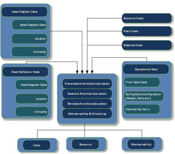
Figure 25 – Crossrail Maintenance Cost Model (CMCM) Process
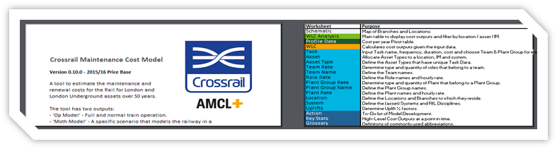
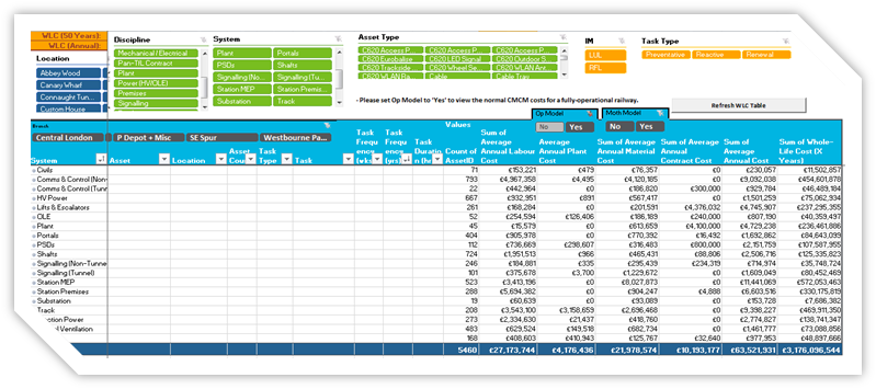
Figure 26 – CMCM Working Model In Excel
5.0 Summary
It is noted that crossrail has many challenges and maintenance and cost analysis is no exception, which need careful consideration from initial strategy to IM integration and handover. The project is in later stages and there will be more challenges to overcome. The current lessons learned and important features that worked well, are highlighted below;
- Maintenance and failure data forms have been invaluable for capturing work volumes to enable calculation of working groups each night. Thus, it was possible to calculate maintenance trains required tasks and its tunnel ventilation requirements . This enabled crossrail to demonstrate maintenance holistically. The T5X schedules for the IM and operation and maintenance manuals (O&M) were based on these which also informed the IM management system.
- The IM boundary document was essential, which covered boundaries between the different IMs and third parties. It included the need for signage at the boundary, and clear boundaries down to fixing level so there is no doubt about accountabilities. A recent derailment investigation in the UK found that the cause was the lack of maintenance between the IM due to the confusion of boundary scope, including signage. This substantiates the importance of the boundary document
- The tunnel ventilation system (TVS) contract was awarded late, whilst SSP architectural and civil design was advanced in terms of its detail, and SSP installers progressed based on the TVS reference design. The TVS is large, heavy, and noisy which has a big impact on the architectural, civil, M&E elements. Challenges were found with A&M including acoustics i.e. louvres, doors, noise mitigation. A key lesson is to integrate the TVS final design with the SSP design at the earliest suitable stage to reduce challenges of this nature.
- As the overall life of the railway is 120years, each supplier had to demonstrate that their design was compliant for A&M before construction of systems. Equipment needs to be operated, maintained, and replaced, and to demonstrate this the A&M strategy document was critical to prove (on paper) A&M could be undertaken. The suppliers also added to this by demonstrating, (via 3D models), A&M, in workshops during design development
- The WLC policy was to seek compliance statement from suppliers that WLC principles have been met. However, the project did find some cases where WLC principles were declared, but not met. An example is air conditioning (AC) systems for SSP, where change of design was required to remove or alter ventilation design. This was due to railway systems power loads reducing and common understanding of system design requirements. The result was to remove or change for WLC compliance.
- The maintenance strategy, principles, and development plan and CMCM were outsourced. Although very good statements, concepts, principles, and policies were provided the hierarchy, structure, and requirements were multiple. Requirements were in all three which were similar and repeated, and probably better undertaken in house with a specification for requirements from a single strategy. Finally, care is needed if outsourcing cost models where intellectual property rights may restrict access to data or formulae in the long term and to hand over to the IM.
References
[1] Effective MEP Techniques and Design Strategy for Large Subsurface Metro Projects. Jonathan King (Crossrail project – Infrastructure design and construction Volume 4 ISBN 978-0–7277-6359-4, pp 57-70).
[2] Effective RAMS Effective Reliability, Availability, Maintainability (RAM) and Safety (S), Principles and Guidelines for Large Subsurface Metro and Main Line Projects. Jonathan King (IET conference – ICRE 2018).
Acknowledgements
Professor Rhys-Vaughn Williams for his continuous support to technical papers during the project and both Rhys and Simon Bennett for their support on the learning legacy programme.
[1] Not all steps were undertaken in the analysis of every critical asset
-
Authors

Richard Consterdine MIMechE MIAM - Crossrail Ltd
Richard has been working on the Crossrail project since 2013, as Crossrail’s Maintenance Planning Engineer. Richard is responsible for ensuring that Crossrail delivers via its contractors; a railway that can be safely and efficiently maintained and that it meets the demanding RAM requirements. This provides vital assurance to the eventual infrastructure maintainers and the Train Operating Company that the railway can be accepted at handover.
Richard has been in the Railway Industry since 1987, previously working on London Underground and the Docklands Light Railway. Roles have included projects, engineering, access planning, contract management and the maintenance of train fleets and infrastructure.

Jonathan King FIET - Crossrail Ltd
Jonathan has been working on the Crossrail project from 2006, firstly as a Crossrail supplier MDC, and FDC and more recently for Crossrail as an Engineering Manager and Engineering Safety Manager. Jonathan’s responsibility has mainly covered systems design, delivery, construction, and safety engineering aspects.
Jonathan has been in the Railway Industry for nearly two decades, working on projects such as CTRL section 2, Thames Link and SSL 4LM. Jonathan is also undertaking research on the Crossrail project under a programme affiliated with the University of Birmingham (UOB) for Reliability, Availability, and Safety (RAMS) and Integration.