New Taxi Facility on Heritage Structures at Paddington
Document
type: Technical Paper
Author:
Adrian Douglas Eur Ing, MEng CEng MICE, Chris Levy, Param Hartop, ICE Publishing
Publication
Date: 03/11/2014
-
Abstract
As a preliminary part of the Crossrail works at Paddington Station, the existing deck spanning platforms and railway tracks is being transformed from a disused goods depot into a taxi and passenger interchange facility. Paddington Station is a Grade 1 listed heritage structure and all modifications to the existing fabric need to be sympathetic to the heritage environment.
The original deck was assessed for highway loading and additional loads from the new structures. A reinforced concrete framed building, constructed c.1920 using the Hennebique system had significant areas of delamination and corroded reinforcement. Surveys and evaluation of current condition generated a prioritised repair strategy. All work has been carried out in and around operational railway infrastructure, within a congested urban site, which has added complexity to both design and construction solutions.
-
Read the full document
1. Introduction
This paper describes how as part of the Crossrail project the some of the various areas and levels of the site were changed to provide the new facility. The condition and use of the site before the works and the historic development of each area is described first, followed by the works carried out to create a unified facility. A general view of the new works areas is shown in Figure 1.
Figure 1 – Arrangement of new works
Construction of the Crossrail station at Paddington required the relocation of the existing taxi rank from Eastbourne Terrace on the south side of the main line station. A suitable space existed on the unused parcels deck but with no clear means of access.
London Underground have an ongoing programme of providing step free access to platforms where practicable and relieving congestion. Significant congestion had been created at the Hammersmith and City line platform due to a recent reconfiguration hence the required upgrading.
An integrated project meeting all of these demands was developed which provided:
• Taxi passenger interchange facility on the parcel and Hammersmith and City line deck;
• New concourse for the Hammersmith and City line station;
• New north entrance to the station complex on to a new plaza adjacent to the canal;
• New platform level concourse giving access to the taxi deck; • Vertical circulation core between platform level and taxi;This paper concentrates on the assessment and alterations to the Hammersmith and City line deck and repairs to the Mint building over the platform level concourse.
2. Pre-project and historical use of the site
2.1 General
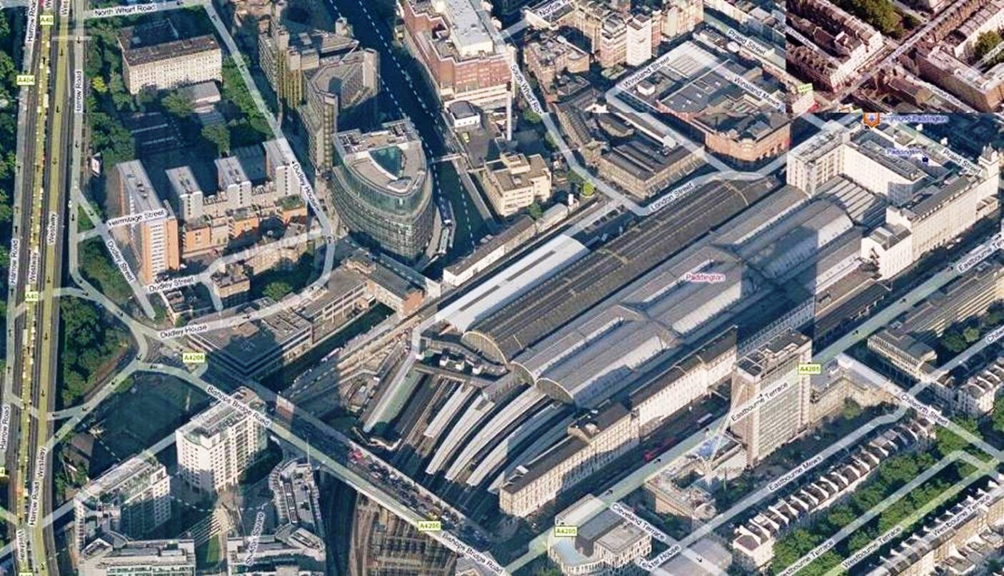
Paddington Station is a major London Terminus for main line trains from the west of England and Heathrow airport. An aerial view of the site before the start of the works is shown in Figure 2. The station is served by three underground lines; the deep Bakerloo line and the shallow Hammersmith and City and Circle lines. The Hammersmith and City line runs along the north side of the station at the same level as the main line tracks. The surrounding area is mixed use with offices, flats and shops at street level. A hospital is adjacent to the station. The site slopes generally from north to south with the mainline track level in cutting 7m below. Bishop’s Bridge Road bridge spans across the main line tracks at the west side of the site which is significant link in the local road network. A spur of the Regents Canal runs parallel to the tracks on the north side.
Paddington Station was first constructed on this site in 1854 [1]. The station was extensively re-modelled several times and included construction of a fourth span to the train shed and additional platforms between 1909 and 1916. The whole station complex is a Grade 1 listed heritage structure.
Figure 2 – Aerial view of Paddington Station before the works
2.2 Hammersmith and City Line deck, Parcels deck, London Street deck
The current Hammersmith and City line station is on the site of the original Bishop’s Bridge Road station, a terminus of the first underground railway opened in 1863. This station was largely removed in 1933 with the construction of new platforms.
London Street deck was constructed over main line platforms. The zones of the deck are shown in Figure 5.
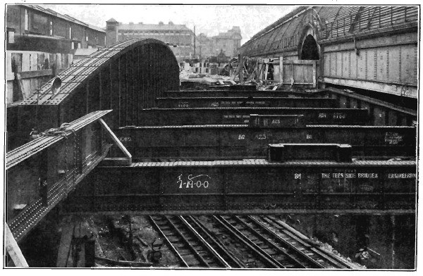
The Hammersmith and City line deck was constructed over the tracks with a grillage of steel beams supporting brick jack arches. At one end of the deck, the track are at a high skew and the ‘hog back girder’ was constructed over the lines to accommodate this. The ‘hog back girder’, shown in Figure 3, was an exceptional 126t beam at the time of construction.
Figure 3 – Hammersmith and City Line deck under construction showing ‘hog back girder’
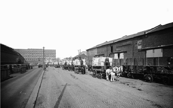
Figure 4 – Early use of Hammersmith and City Line deck
The existing decks over the Hammersmith and City line and main line platforms had previously been used for the parcel rail service distribution centre and was now disused. A previous contract overslabbed the deck in conjunction with renovation of span 4 of the adjacent main line station roof.
Figure 5 – Zones of the taxi deck
2.2 Mint Building
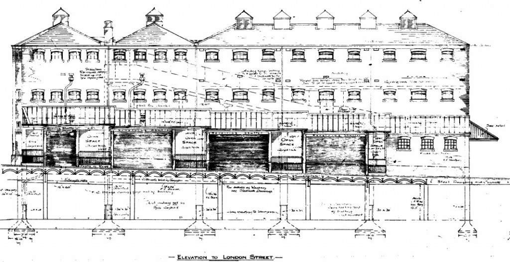
The oldest part of the Mint Building was constructed in 1878. The portion over the platform was extensively re-built at the same time as the construction of the London Street deck between 1917 and 1922. The Mint building was constructed as stables, with support functions, for approximately 1 000 horses. As seen in Figure 4 horses were used extensively to handle milk and mail deliveries at the station. Figure 7 shows an elevation of the building.
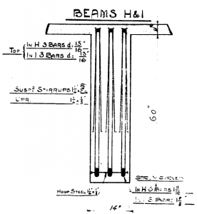
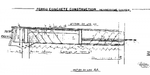
Figure 6 – Details of Hennebique system from record drawings of Mint Building
Figure 7 – Elevation of Mint Building from record drawings
The concrete structure is described on the drawings as ‘ferro-concrete to the Hennebique system’. The structure was designed by LG Mouchel who had the
licence for the Hennebique system in the UK [2].Figure 6 shows typical details of the Hennebique system structure from the record drawings.
The Mint Building, over the operational support area and concourse adjacent to the platform, was being used as part of the hospital. The columns supporting the building at concourse level are the responsibility of Network Rail.
3. Provision of new facilities
3.1 Consents process
The Crossrail Act 2008 grants deemed planning permission for Crossrail works. This includes scheduled works, such as the railway tracks and tunnels, and ancillary works, such as the works at described in this paper. The deemed planning permission is subject to conditions set out in schedule 7 to the Act. This requires certain matters are approved by the local planning authority prior to the start of works; these matters include plans and specifications of the proposed works above ground. Detailed planning applications were prepared and submitted to provide details for Westminster City Council, and for the Heritage Method Statements, which also required agreement with English Heritage.
The Crossrail Act 2008 disapplies the requirement for Listed Building Consent for certain works within Paddington mainline station, however in order to ensure works to listed heritage structures were carried out in a satisfactory manner; the Secretary of State entered into legal agreements (known as Heritage Deeds) with the local authorities which require approval by the authorities of the method by which the works will be carried out. Detailed method statements were prepared for the PIP works in relation to Crossrail and submitted to Westminster City Council for approval.
The works to the London Underground station were outside the scope of the disapplication and a ‘sister’ listed building consent was therefore required for the London Underground station. The team liaised with Westminster City Council pre-submission to ensure that the required information and supporting evidence was submitted first time. The planning specialists worked iteratively with the design and architecture teams to ensure that changes to the design were monitored and consented accordingly. A number of consents for redesign were required.3.2 Design constraints
The infrastructure around the site and heritage considerations on the site imposed the following general constraints on the design: • Complying with Westminster City Council’s preferences for taxi routes,
• Traffic flows on Bishop’s Bridge Road bridge,
• Restrictions of Heritage Deed,
• Weight restrictions on the decks,
• Level differences between entrances and taxi deck,
• Sub structure for over site development.The taxi facility was required by Westminster City Council to connect the taxi rank to the local road network on Bishop’s Bridge Road bridge, rather than at the front of the station, and a 70m long ramp was required to account for the level difference between the bridge and the Hammersmith and City line deck.
3.3 Taxi deck
3.3.1 Assessment
The layout of the various zones of the existing structures forming the taxi deck is shown in Figure 5. To verify that the Hammersmith and City line deck and the parcel deck were suitable for the change of use the structures were inspected and a structural assessment carried out. The inspection indicated that most of the steel members were in a satisfactory condition and recommended repainting and local repairs. The inspection and assessment was carried out in accordance with the UK Highways Agency methodology [3] [4]. The assessment took into account the proposed modifications to the deck which were in accordance with the planning and heritage restrictions.
The assessment concluded that the maximum load that could be carried on the deck was 18t weight restriction due to the limited strength of some members in the deck. This was acceptable due to the
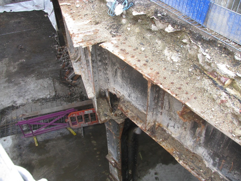
nature of the vehicles usually using the deck and as it was practicable to restrict maintenance vehicles to 18t. A typical condition and arrangement of the beams and column are shown in Figure 8.Figure 8 – Steel beams exposed on the perimeter of the Milk Ramp opening
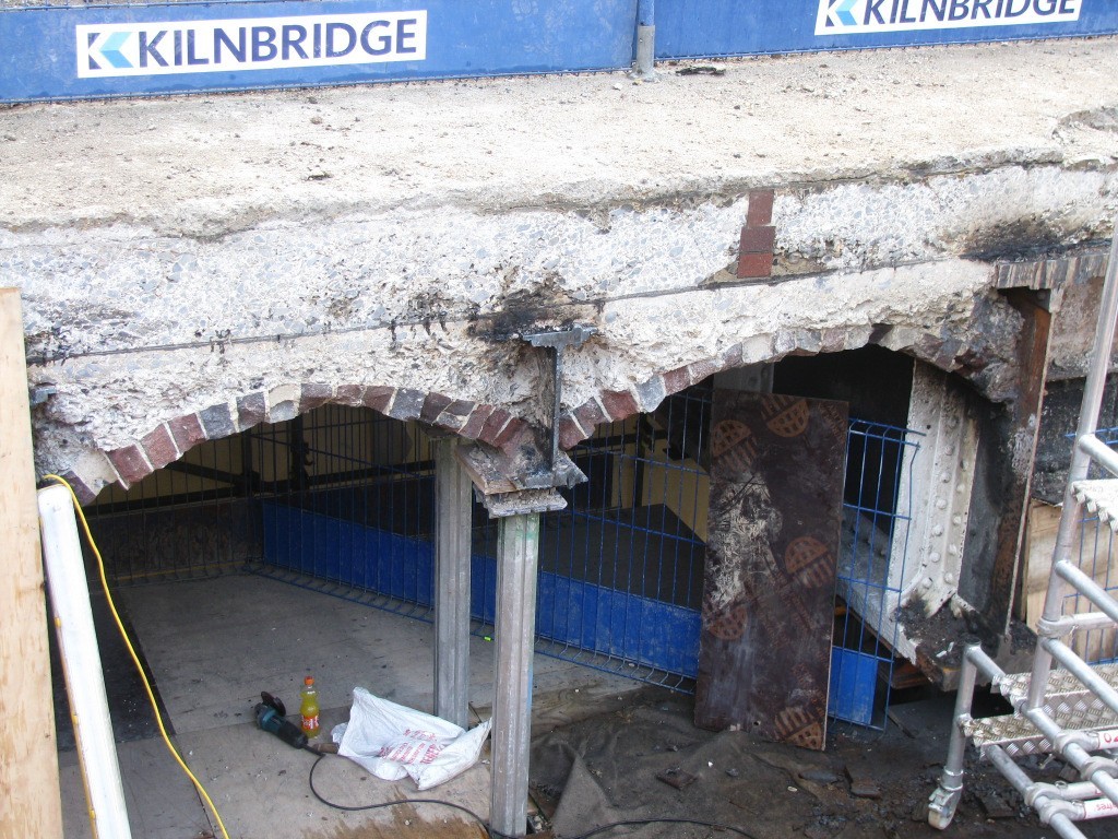
The brick arches were assessed using the empirical MEXE method [5] which showed a significant reserve of capacity for the assessment loads. The large point loads from the taxi canopy were arranged to be over the steel beams. Figure 9 shows the brick jack arches and joists exposed in the side of the opening through the deck for the escalators.
A departure from the usual standards was agreed with Network Rail to reduce the load factor on the non structural permanent loads. The usual factor is typically applied to road surfacing and it was considered unreasonable to apply this to all of the thickness of infill concrete given the degree of certainty over the thickness.
Figure 9 – View of jack arches and joists exposed in side of escalator opening
In order to limit the amount of analysis required a staged approach to the assessment was adopted. Initially the vehicle load was considered to be the standard UK ‘HA’ highway loading pattern with lanes conservatively positioned in any position on the deck. Members which failed this assessment were then considered with the reduced ‘HA’ loading suitable for 18t vehicles and the proposed lane arrangement on the deck. Finally members which failed the second assessment were then considered with actual vehicle loading on the proposed lanes and an accidental vehicle loading on the pedestrian areas behind the bollards. This assessment method required a significant calculation effort for each member and would not have been efficient if it had been used for all of the structural elements.
In total over 500 structural elements were assessed. The assessment results were tabulated for ease of interpretation and provided to the Contractor to enable the development of temporary works and construction planning within the load restrictions.
The assessment resulted in the requirement to strengthen one column during the works. The column was strengthened by filling the hollow steel structure with a high strength grout as this method did not change the appearance of the column and thus complied with the heritage restrictions.
3.3.2 Taxi facility layout
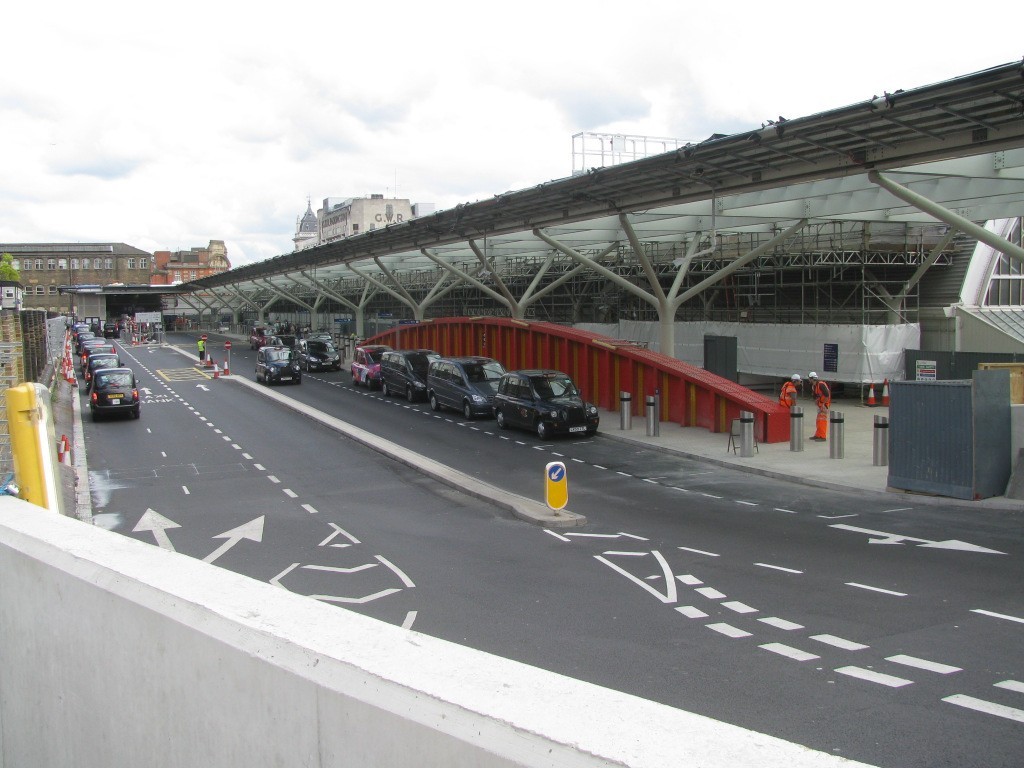
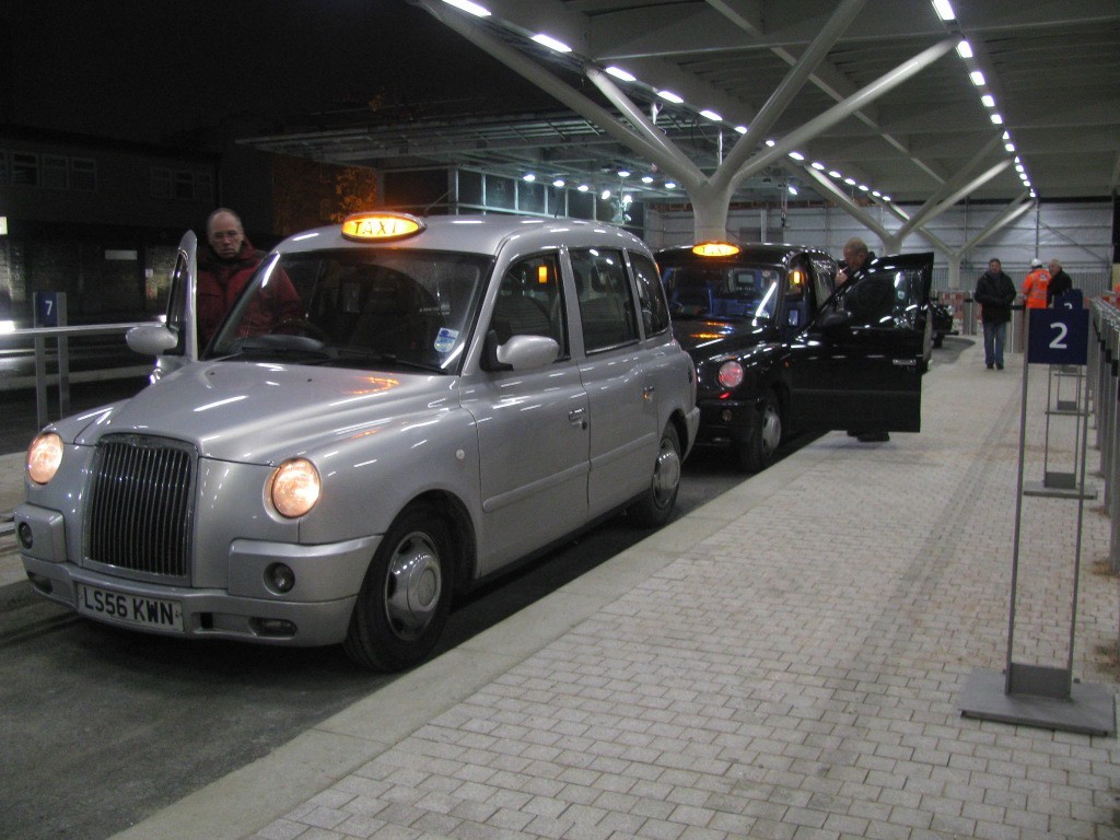
The taxis using Departures Road, before the construction of the new facility, had typical queue lengths of up to 100 taxis over Bishop’s Bridge Road bridge. In order to accommodate the peak demand for taxis, shortly after the arrival of a Heathrow Express train, it was a requirement of the operator of the Heathrow Express that nine pick up points were provided. Six set down bays were provided and a waiting area for pre-booked taxis. A general view of the taxi deck is shown in Figure 10. Queuing space for 60 taxis was provided on the deck with another 10 on the taxi ramp and a dedicated lane on Bishop’s Bridge Road bridge for any additional queuing taxis.
In operation the new facility has loaded 90 taxis in five minutes and 750 taxis per hour during peak periods.
Figure 10 – General view of new taxi deck
3.3.3 Taxi deck canopy
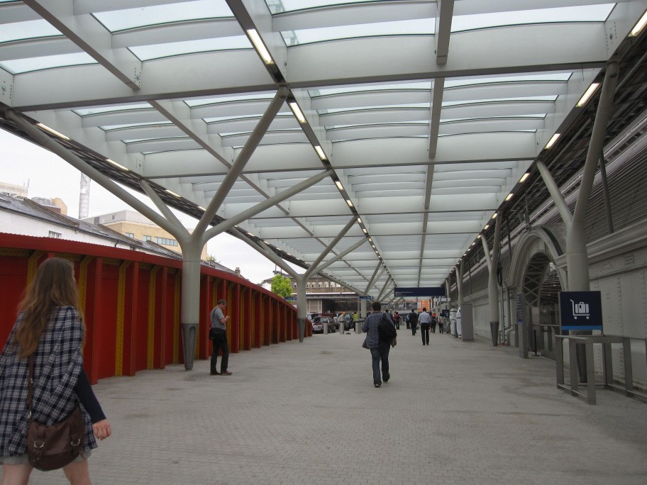
The pedestrian area for the new taxi facility is covered with a canopy. This canopy is supported on columns with four branches connected to a grillage of beams and purlins supporting the curved glass canopy. The canopy is shown in Figure 11 which is a view similar to Figures 3 adjacent to the hog back girder.
The London Street end of the taxi deck is separated from the highway with a glass screen to the full height of the canopy providing weather protection to the escalator opening and passenger queuing area.
Figure 11 – Taxi deck canopy over pedestrian circulation area
3.4 Mint Building
3.4.1 Survey
During the works it became apparent that there were significant defects to some areas of the concrete soffit of the Mint Building. An inspection of the soffit was carried out with a delamination survey over the accessible area. Samples were taken to determine cement content and chloride content. A cover meter survey was also carried out in a representative area.
The area over the affected soffit was a loading platform with stables over the back of house area. It is possible that manure on the floor from this use will have leached into the concrete and reduced the alkalinity of the concrete.
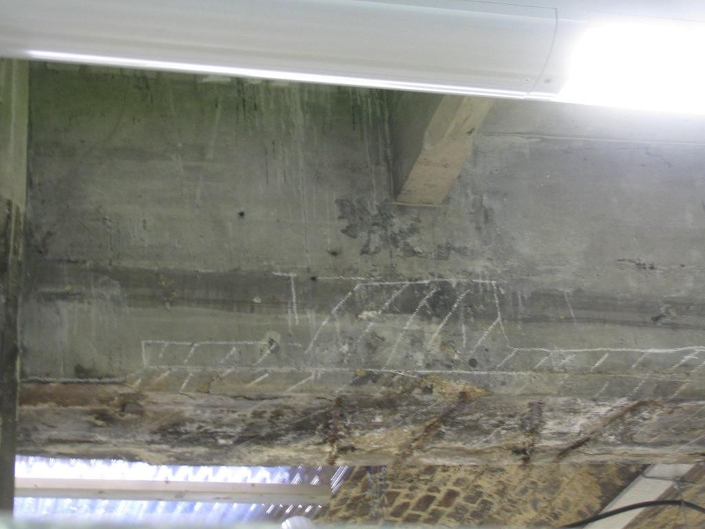
A typical area of delaminated concrete, on the soffit of a beam, with exposed corroded reinforcement is shown in Figure 12.
During the inspection some characteristic defects became apparent:• Significant delamination and corrosion of reinforcement around the perimeter beam. This area is frequently damp with rain through the vents or percolating through the London Street Deck;
• Localised delamination of secondary beams and the soffit;
• Areas where the delamination, survey by hammer tapping, gave neither a sound concrete ‘ding’ or a delaminated concrete ‘donk’ noise – “more of a ‘thud’”;
• Areas with a high concentration of chlorides.It is speculated that the areas which gave a ‘thud’ noise may be the result of softening of the concrete matrix due to acid attack from manure leachate into the concrete. This would lead to the carbonation tests in this area showing significant depth of carbonation, loss of alkalinity is measured and correlated to carbonation. However, the carbonation results were not given for specific locations so this cannot be verified.
Figure 12 – Typical area of delamination on Mint Building beam
3.4.2 Development of repair specification
The ‘Inspection manual for highway structures’ [6] sets out a hierarchy of possible methods to rectify structural degradation:
1. do nothing, but monitor;
2. reanalyse the structural capacity of the weakened element;
3. prevent or reduce further deterioration;
4. improve, strengthen or refurbish all or part of the structure;
5. replace all or part of the structure; or
6. demolish, completely or partially.Given the nature of the visible defects in some areas and the difficulty of gaining access in the future option 1 was not considered appropriate.
The concrete structure was not designed to any presently recognised system and there are few details available of the reinforcement arrangement. It is therefore impossible to carry out a re- analysis of the structure in accordance with present codes which would give a realistic answer. Although sophisticated analysis techniques, possibly verified through testing, would be possible the cost of this did not appear to be justified. It was therefore concluded that option 2 is not practicable.
As a listed structure it is not permitted to partially or fully replace or demolish the structure. Options 4 (excluding repair), 5 and 6 were therefore not appropriate.
Option 3 (or repair under option 4) was therefore adopted. Repair in a like for like manner did not require further heritage approvals.
The Concrete Society report ‘Repair of concrete structures’ [7] and BS 5104 part 9 [8] gives a more specific list of options for repair of concrete structures:
1. do nothing for a certain time;
2. complete or partial demolition and rebuild;
3. patch repair of local damaged areas;
4. ingress control via coatings, membranes, sealers, water stops, enclosures or other barriers;
5. impressed current cathodic protection;
6. galvanic cathodic protection;
7. electrochemical realkalisation;
8. electrochemical chloride extraction;
9. corrosion inhibitors.Of these only Options 3 and 4 are appropriate. Options 1 and 2 have been discussed and rejected above and Options 5 to 9 are either difficult to implement on the Mint Building soffit or most suited to rehabilitating concrete with significant chloride contamination.
In order to limit future degradation of the structure to minimise future maintenance requirements it was essential to control the ingress of water and possible chloride contamination. London Street Deck was waterproofed and louvres to the air vent openings are proposed to control future water ingress and chloride contamination. The waterproofing required the removal of the existing surfacing, profiling of the top of the infill concrete to create falls, and provision of a sprayed waterproofing membrane.
The repair specification required all areas with delaminated concrete to be broken back to sound concrete, the reinforcement to be cleaned of loose rust and primed, replacement reinforcement to be spliced in where appropriate, the concrete is to be reinstated with a fine aggregate concrete or proprietary repair mortar. Sacrificial anode protection to the reinforcement, to control incipient anode corrosion at the interface between the repair concrete and the existing concrete, was required.
3.4.3 Requirement for future inspections
To ensure the continued functionality of the structure and to limit the extent of future repairs regular inspections are required and ongoing repairs are to be expected.
Several areas on the repaired structure were identified as at higher risk of future degradation. It was recommended that these areas should be targeted for close inspection and testing during future inspections.
3.5 Platform 12 operational support areas
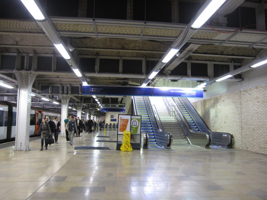
The existing operational support area adjacent to the platform was significantly remodelled during the works. The left luggage facility was temporarily relocated and all of the existing facility demolished in phases. Part of the platform was narrowed to allow an unpaid concourse to be introduced to the bottom of the escalator, shown in Figure 13 (before the barrier segregating the platform from the concourse was constructed).
Figure 13 – Escalator from platform 12 to taxi deck
The below ground drainage was replaced to suit the additional flows from the taxi deck above. A new ground slab was constructed to support the structures for the replacement retail stores and left luggage which are independent from the heritage structures.
Replacement ventilation ducts were constructed for the exhausts of the diesel trains using the platforms. These ducts were taken via a plant room through the lift building to discharge above the taxi deck canopy.
4. Conclusion
The project safely and successfully delivered the new taxi and interchange facility, seen in figure 14, making effective use of the existing heritage structures.
Figure 14 – Arrival of first taxi
5. References
[1] Carpmael, R., The development of Paddington Station, The structural Engineer, 1936
[2] McBeth, Douglas: Francois Hennebique (1842–1921) – Reinforced concrete pioneer, Proceedings of the Institution of Civil Engineers, 126-2, 1998
[3] BD 63/07, Inspection of Highway Structures, DMRB Volume 3, Section 1, Part 3, Highways Agency, 2007
[4] BD21/01, The assessment of highway bridges and structures, DMRB Volume 3, Section 3, Part 3, Highways Agency, 2001
[5] BD16/97, The assessment of highway bridges and structures, DMRB Volume 3, Section 3, Part 4, Highways Agency, 1997
[6] Inspection manual for highway structures, TSO, 2007
[7] Repair of concrete structures with reference to BS EN 1504, Technical report No 69, Concrete society 2009
[8] BS EN 1504-9, Products and systems for the protection and repair of concrete structures – Definitions, requirements, quality control and evaluation of conformity – Part 9: General principles for the use of products and systems, BSI, 2008
-
Authors
Adrian Douglas Eur Ing, MEng CEng MICE - Mott MacDonald
Principal Engineer
Chris Levy - Mott MacDonald
Project Director Mott MacDonald
Param Hartop - Crossrail Ltd
Project Engineer
-
Acknowledgements
Crossrail, Project promotion, figures and photographs
Weston Williamson, Architects
Carillion, Construction work
Transport for London, Coordination withroad network
Westminster City Council, Planning and Heritage approvals

