Prevention of Tunnel Flood – Integration Testing
Document
type: Technical Paper
Author:
Wing Fung PhD MSc BSc(Eng) CEng MCIBSE
Publication
Date: 02/12/2021
-
Read the full document
Introduction
One of the railway operation hazards is tunnel flood which might lead to prolong service disruptions and extensive asset damages. Flood prevention measures including catchment and collection designs, dewatering provisions and monitoring and control design are in place in Crossrail to mitigate the hazard. Another important consideration is to ensure that the finished drainage system is free from blockage or accumulation of construction stage debris which will adversely affect the overall performance of the system. At the commissioning stage, assurance evidence is compiled through integration testing to confirm that the underground railway tunnels are protected from occurrences of flooding. This involved co-ordinated action of various system wide civil, mechanical and electrical installations, validation of the potential source of water ingress into the tunnel, the means of channelling and collection of flood water and timely discharge of the flood water to the area wide drainage network and its integrity. The latter includes the piping, water pump as well as power supplies, de-watering control and condition monitoring systems.
This paper highlights the pertinent issues that need to be considered on implementing integration tests for a wide area railway track drainage system.
System Overview
In Crossrail tunnels, the main source of water ingress is the water discharge from the tunnel fire hydrants during routine maintenance test and firefighting. Apart from a section of retrofitted tunnel, all Crossrail railway tunnels are new built to the latest water proofing specification hence ground water or seepage water is not a major source of water ingress. The probability of burst pipe is extremely small through quality control measures and rigorous product and system testing.
The Tunnel Fire Main (TFM) has interfaces with station shaft and portal locations which provide interconnections for the delivery of TFM water supplies and discharge of water influxes via the Tunnel Plumbing and Drainage (TPD) network. The Tunnel Fire Main is split into 17 sectors. The TFM delivers water to the tunnel hydrant connection points located on the tunnel walkway. Figure 1 shows a typical fire hydrant installation in the railway tunnel.
The track drainage system is designed for a maximum flow rate of 34L/s in the tunnels. This is related to flow generated during fire fighting and testing, which is several magnitudes greater than the base flow from seepage and fire main leakage. The design does not consider accidental conditions such as a fire main burst. The discharge water is collected through a series of tunnel sumps.
For the Central and Thames tunnels, two-stage pumping is provided; drainage from low point sumps is discharged to the nearest station or intermediate shaft and then separately pumped to ground level. Flows gravitate to the low point sumps which are located at cross passages and a niche sump. The sumps are located as follows:
- 10 No. tunnel low point sumps located within tunnel cross-passages;
- 1 No. tunnel low point sump located within a tunnel niche;
- 7 No. station sumps located within sub-surface stations;
- 3 No. sumps located within intermediate shafts;
- 1 No. sump at Connaught Tunnel.
The pumped drainage system includes the following features: dual power supplies with auto changeover; dual sump level and hydrocarbon detection control systems; dual discharge pipes – one from each half of the sump, except at specific niche and cross passage where both pumps shall deliver into a single discharge pipe. Pumped drainage shall be provided at rates up to 34l/s (excluding the Connaught Tunnel) to remove the tunnel drainage collected at tunnel low points and intermediate shafts for discharge to sewers and watercourses. This flow rate is when all pumps are operating at full speed and equals the volume of water collected when four fire-fighting hoses are in use.
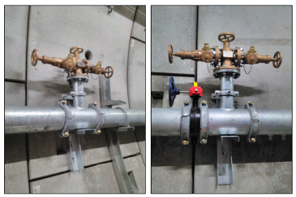
Figure 1. Fire Hydrant Connection Points
Integration Test Requirements
Integration test for the flood prevention measures covers the following areas:
- Validation of the water ingress flow rate (TFM flow test). The test is to demonstrate that hydrants flowrates are in accordance with BS9990 where the track drainage discharge capacity is based.
- Verification of the integrity of the open channel flow pipe section through CCTV survey. Carry out sample surveillance work (i.e. pipe tracing dye) to demonstrate integrity or no blockages of the underground track drainage pipes below the track slab at locations selected by Crossrail. The test results would confirm integrity and no-blockage at various sections of the drainage network.
- Verification of the integrity of the closed pipework integrity through pressure test. Carry out pressure test on Tunnel Pump Drainage end to end from catch pits to stations, shafts and portals discharge point.
- Verification of the remote control and condition monitoring- sump pump control and SCADA Performance test. Carry out end to end testing of the SCADA control and monitoring of critical sump pumps. Remote condition monitoring control fully functional in the sample tests.
- Validation of the surge and steady state hydraulic capacity of the as installed track gravity drainage and the integrated performance of the installed dewatering installation and control. Water discharge from the fire main at the tunnel and collected at the critical sump via the surface gullies. The tunnel fire main shall maintain 2000 litre/minute discharge for 5 minutes to demonstrate effectiveness of the drainage system. Test methodology to be agreed in accordance with Crossrail requirements. Confirm that water discharge from the fire main will not impair evacuation/ intervention and resuming train/ tunnel services. No overflow from tunnel gullies or flow diverted to other areas. Evacuation/ intervention path not adversely affected. Tunnel services not affected while draining away the water.
Pertinent issues on the planning and execution of tests
Validation of the water ingress flow rate
The test serves the following purposes:
- Confirming that sufficient fire fighting water will be supplied to the tunnel fire main at the right pressure.
- Confirming that a control amount of water is discharged into the running tunnel without causing flooding and eventual service disruption and extensive asset damage.
The test primarily relies on the water supply from the header tank with top up from the street hydrant system. The test only provides verification of the instantaneous water discharge rate from individual connection points in the tunnel on the assumption that a healthy supply of water is available. The test does not necessarily confirm that the local street hydrant system is able to supply the water flow to put off a design fire when multiple water connections are made.
Verification of the integrity of the open channel flow pipe section
The following were checked during the survey:
- The structural integrity of the including defects such as cracks, fractures, moderate joint defects, holes, breaks and surface wear,
- Service or hydraulic defects of the drains for the capability to meet its service requirements to avoid loss of capacity, and potential for blockages and water tightness,
- Miscellaneous defects which relates to general items concerning the drain such as changes to pipe size, shape and material,
- Construction defects relating to the general construction of the drain connections/ junctions, lining and sealing defects.
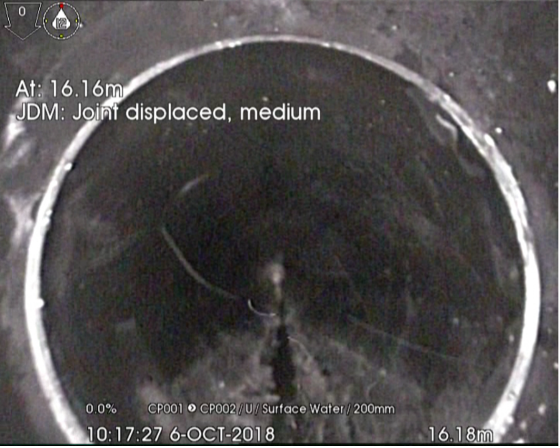
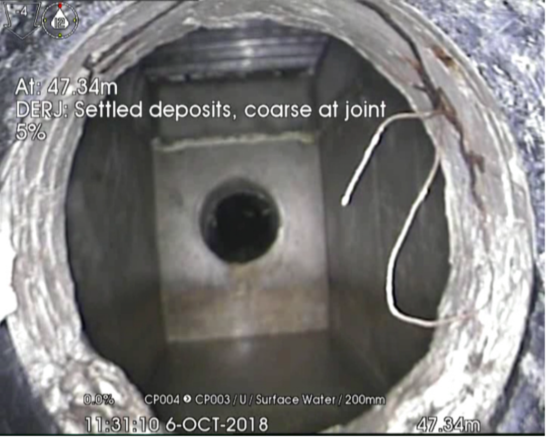
The record photographs in Figure 2 show the condition of specific sections of the drainage pipes in the CCTV survey. Displacement of joints and settlements are common problem with non-pressurised drainage pipework.
In the survey construction related defects were identified and attended to for the drainage system. The result of the survey indicated that a significant amount of debris was found within the pipework. Not only concrete slip that can be expected, but large objects, plastic bottles and lumps of concrete. The occurrence is not unexpected due to the common malpractices during the construction stage of the work. These defects will jeopardise the long-term functionality of the drainage if they are overlooked or ignored. This is a problem with railway track drainage because of the difficulties of visiting or service the drainage pipes/ sumps / pumps once the railway is in service. These are areas that are extremely difficult to access in an operating railway- not only getting down the tunnels to the cross passages, but also with the sumps being confined space areas.
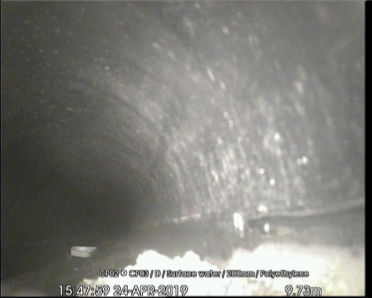
Settled deposits, hard or compacted 25% cross-sectional area loss
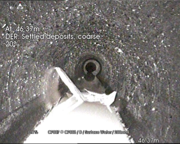
Settled deposits, coarse 20% of the pipe bore
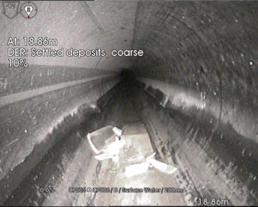
Settled deposits, coarse 10% of the pipe bore
Figure 2. Record photographs of pipe section taken in CCTV survey
Verification of the integrity of the closed pipework
Pressure tests were carried out to confirm the integrity of the pipework system. Although there are established routines to test pressurised pipework, the pertinent issue of the exercise is to determine the appropriate test pressure for the specific sections of the pipework system, which vary from one section to another. A systematic approach was used in Crossrail to establish the appropriate the test pressures for the use.
BS EN 805 section 11.3.2 describes a number of methods to determine the test pressure. The flow chart in Figure 3 illustrates how the system test pressure was established.
Figure 3. Flowchart to determine the Test Pressure
Test pressures are calculated from the Maximum Transient Pressure and the Pump Closed Valve Heads. The Standard Test Pressure (STP) will be the largest of STP – Surge Calculated using the Maximum Transient Pressure, or STP – Surge non-calculated using the Pump Closed Valve Head. The Table in Figure 4 indicates the test pressures adopted at different sections of the pressurised pipework network.
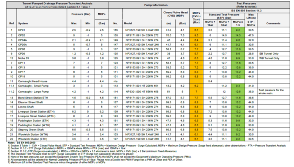
Figure 4. Selection of Test Pressure
The following test routine was adopted:
- Preliminary Phase- BS EN 805 Clause 11.3.3.2. Pressure to increase to 10% of the test pressure and held for a period of time to allow the system to stabilize. Further increments at 40%, 70% and 100%.
- Pressure Drop Test- BS EN 805 Clause 11.3.3.3. Pressure drop test was carried out where there are a significant number of changes in direction.
- Main Test Pressure (using the Standard Test Pressure) in accordance with BS EN 805 Clause 11.3.3.4 Pressure Loss Method. The acceptance criterion: max pressure loss of 20kPa over 1 hour.
- Final System Test using the normal operating pressure BS EN 805 Clause 11.3.3.5. Operation of the pump and check the untested interface joints between the Tunnel and Cross Passage, Tunnel Sections, Sump and Station/Shaft Pipework. All joints identified as untested will be tested and inspected.
Hydraulic Test was carried out in accordance with BS 9990:2015. The Maximum Static Pressure will be used (at the low point). All joints identified as untested will be tested and inspected.
Verification of the remote control and condition monitoring
The test addresses the following issues:
- Verification of the control action on operation and monitoring of the working status of the sump pumps and associated power supply
- Real time condition monitoring of header tanks and sump pits
- Real time detection of hydrocarbons and flammable gas in the sump pit
- Real time monitoring of the working status of the trace heating of outdoor wet pipes.
End to end verification test of all point addresses and control logic of the SCADA system is a labour intensive but indispensable exercise to ensure effective remote control and monitoring of the flood protection system. Common anomalies that were discovered in the verification test are:
- Inconsistency on nomenclature e.g. asset name and location reference
- Pump control fails to react timely under automatic control
- Differences in system control strategy in work sites because of different PLC control algorithm.
- Local PLC time clock fails to synchronise with the master clock
- Cyber security protocol was not followed through.
Figure 5 provides an illustration of the remote workstation display on the sump pump control.
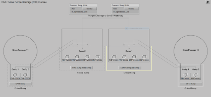
Figure 5. Sample screen shot of the remote control and monitoring workstation
Validation of the hydraulic capacity of the track gravity drainage and the integrated performance of the installed dewatering installation and control
This is the integration test to demonstrate the ability of the drainage to take care of a water influx event. Water will be discharged into the selected tunnel locations via the tunnel fire main for a set time of five minutes. The test is intended to be carried out at two different locations:
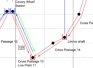
- Westbound between Limmo Peninsula Shaft and Canary Wharf, considered high risk of flooding. Water collected at low point 11 CP13, as illustrated in Figure 6.
- Eastbound between Liverpool St and Farringdon Stations, considered as low risk of flooding. Water collected at low point 5 CP5A.
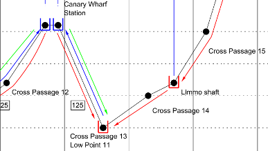
Figure 6. Drainage layout of the Test Location
During the discharge period the rate of flow will be monitored and recorded. The discharge water will be collected at the relevant tunnel sump which will then pumped out of the tunnel environment. The test will also provide an assessment of the time required to resume the train service following an incident of this nature. Acceptance criteria for the test were as follow:
- Tunnel intervention and evacuation routes was not compromised
- Tunnel infrastructure handled the water discharge effectively
- Extent of any local flooding. Record depth measurements of any water collection or ponding locations
- Tunnel systems remain unaffected by the water discharge
- Effective remote monitoring of the de-watering pumps and alarm status of other tunnel services via SCADA.
A desk top study was subsequently adopted instead of a physical test. This is on the basis of proven design information and verification tests already carried out on the related subjects.
Conclusion
Integration tests were successfully completed to validate the main assumptions on the system performance (in the case of tunnel drainage system, the rate and volume of water ingress into the tunnel); verify the performance of the drainage system and confirm that an effective local and remote control and monitoring system is in place.
This paper also highlights important issues to be considered in further planning and execution of integration tests for tunnel drainage system in future projects. In addition, it is important that measures are put in place to prevent dumping of wastes into a drainage system during construction stage.
-
Authors

Wing Fung PhD MSc BSc(Eng) CEng MCIBSE - Arcadis
Technical Director (MEP), Arcadis
Wing is is a Chartered Engineer with over 30 years’ experience as a technical specialist engaged in mass transit system planning, design, project management, technical assurance, commissioning, energy management, operation and maintenance, and asset renewal. Wing has been with the Crossrail project in the CRL Chief Engineer Group since 2013, overseeing mechanical design, systems integration and T&C.
Specialties: Building Services, Mechanical Engineering, Computational Fluid Dynamics, RAM studies, Systems Integration, Requirement Management, Testing and Commissioning.