Protection against fire for the UK Crossrail tunnel structures
Document
type: Technical Paper
Author:
Mike King BSc CEng MICE, ICE Publishing
Publication
Date: 09/07/2018
-
Read the full document
Introduction
The UK London Crossrail project is a high capacity and high frequency transportation system with tunnelled sections passing beneath a densely populated urban environment, and running close to numerous high-rise buildings, buried services and operational metro systems. The safety of the system users, staff and personnel responding to an incident, as well as of all those in close proximity to the underground sections must be maintained even under the most onerous of anticipated loads and events.
In recent years there have been a number of high profile fire-related incidents within operational tunnels causing fatalities as well as significant structural damage to the tunnel linings. Where the tunnel linings ultimately support other structures, it is imperative that this support is maintained following a fire event until the safety of all potentially impacted people can be guaranteed. The need to meet this requirement has driven the Crossrail tunnel design and testing programmes; it required consideration of the best guidance provided by current standards and legislative requirements, while challenging and comparing these against the anticipated loadings and events specific to this project, leading to the development of robust solutions that will exceed requirements.
Project description
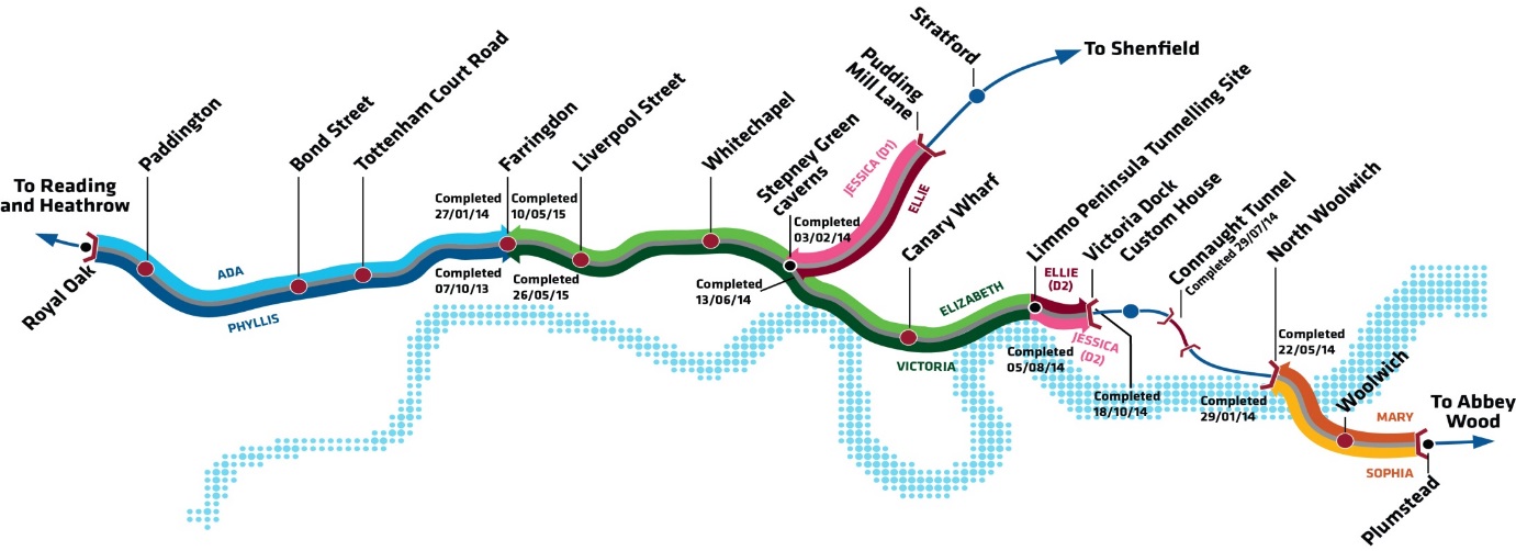
The London Crossrail east-west link extends from Reading in the west, to Shenfield and Abbey Wood in the east. The central section from Royal Oak in West London to Plumstead and the Olympic Stadium in the east is predominantly constructed in tunnels up to 40m below ground level which are the subject of this paper (see figure 1). The scheme will provide a 10% increase in existing rail capacity in London enabling an additional 200 million journeys each year linking up major business centres and existing transportation interchanges beneath the congested and built-up capital.
The central tunnelled section consists of 42km of running tunnels constructed using precast concrete segmental linings (PCL) behind pressure balance tunnel boring machines. There are over 12km of sprayed concrete linings (SCL) and cast insitu linings within five new underground stations, six crossover and bifurcation caverns, and numerous access passages, cross passages, adits and ventilation tunnels.

Figure 1 – Central tunnel section of Crossrail
General details of the scheme are described in many papers published over recent years, and references 1 and 2 contain general details of the tunnelling aspects, with references 3 to 5 containing papers that provide more detailed information on a wide variety of project aspects.
The main tunnelling contracts on the project with tunnel structures designed to resist fire, and discussed in this report, are summarised in table 1.
Table 1 – Summary of main tunnelling contracts with test results considered in this report
Contract No. Principal Contractors Main Construction elements with test results considered in this paper C300 BAM / Ferrovial / Kier PCL from Royal Oak to Farringdon
SCL at Fisher Street Crossover caverns between Tottenham Court Road and Farringdon
C305 Dragados / Sisk PCL from Victoria Dock portal to Farringdon, and from Pudding Mill Lane to Stepney Green
SCL at Stepney Green bifurcation caverns and Limmo shaft
C310 Hochtief / Murphy PCL from Plumstead Portal to N. Woolwich Portal C410 BAM / Ferrovial / Kier SCL at Bond Street Station and Tottenham Court Road Station C435 BAM / Ferrovial / Kier SCL at Farringdon Station
Cast insitu at Farringdon Station
C510 Balfour Beatty / BeMo / Morgan Sindall / Vinci SCL at Liverpool Street Station, and Whitechapel Station and crossover caverns at Whitechapel Geological setting
The geographic spread of Crossrail across London has meant that the project’s tunnels have encountered and traversed most of the strata beneath the city, down into the underlying chalk. References 1 to 5 contain specific details of the ground conditions; for the purposes of this paper, the conditions can be described as varying from fractured and weathered rock, to stiff over-consolidated clay, to sands and gravels with self-supporting stand-up times ranging from several hours to less than a minute. The tunnels are all below the water table, and although the clay stratum in London is often described as impermeable, this is not always the case as it contains joints, faults and sand lenses. Dealing with water during construction, and minimising its ingress into the tunnels during the design life, is a consideration in all of the geology below London.
General description of tunnel lining systems
Precast Concrete Segmental Linings (PCL)
Twin tunnels running between stations were constructed from steel fibre reinforced precast concrete segmental elements 300mm thick. Some segments also have light reinforcement cages within them to cater for punching shear forces in the short sections of tunnel with floating track slab. Each ring comprises seven segments and a smaller key and a finished theoretical internal diameter of 6.2m (see figure 2). The rings are tapered and were rolled for alignment control, but are nominally 1.6m long and were erected with two steel bolts across each longitudinal joint, and three dowels across the circumferential joints (except at the key which has one dowel). Steel bolts with the potential to fall out if loosened were removed sometime after ring erection to eliminate the risk of future disruption to the operational railway.

Figure 2 – Crossrail precast concrete segmental running tunnel
Sprayed Concrete Linings (SCL)
The SCL tunnels on the project were built up with multiple layers of sprayed concrete, waterproof membrane and fire protection as shown in schematic form in figure 3. Some layers were sprayed in two or more passes depending upon tunnel size and lining thickness, for example P1 and P2 for the primary lining as indicated in figure 3. The majority of the SCL tunnels are generally close to circular with finished internal diameters ranging from under 5m up to about 10m. The crossover and bifurcation caverns are closer to an elliptical shape with an excavated diameter across the major axis (horizontal) of over 17m and across the minor axis (vertical) of about 14m, but were constructed with a similar layer arrangement to that shown in the figure 3.
The different layers were generally steel fibre-reinforced; the exception was the regulating layer on the primary lining, which had a smaller aggregate and no fibres, and the fire protection layer on the secondary lining, which had no steel fibres but included monofilament polypropylene fibres as discussed later in this paper. At some locations, for example close to junctions with cross passages and in the larger and flatter crossover caverns, reinforcement was introduced into thickening layers inside the primary lining, or within the secondary lining to resist higher bending stresses. On Crossrail, the primary lining forms part of the load-carrying permanent works and has the same design life as the secondary lining (120 years).

Figure 3 – Schematic of SCL layer build up
Project fire protection requirements
Fire within a transportation tunnel represents one of the major hazards for a project and the risk is mitigated through a number of safety systems, including the lining itself. The systems might include safety-related aspects such as detection systems, operational procedures, and evacuation and intervention procedures, through to the provision of signage, safe escape routes, communication systems and places of safety. This paper only be deals with the impacts of a fire upon the main tunnel structures and their load carrying capacity.
The main source for defining the safety requirements for the project is the European Technical Specification for Interoperability (TSI) – Safety in Railway Tunnels6 (2008 edition) that was current at the time of scheme development and project design. The TSI mandates that the integrity of the structure shall be maintained in the event of a fire for a period sufficiently long to permit self-rescue and evacuation of passengers and staff, and the intervention of rescue services without the risk of structural collapse. However, this version of the TSI makes no specific provision for the longer term stand-up time and ground support to protect adjacent structures and tunnels. The Crossrail project made the decision that the hazards associated with the risk of loss of ground support in this urban environment during or after the design fire scenario were too great and that managing closure of adjacent underground metro lines, and evacuation of other potentially impacted assets were too complex and potentially subject to error in implementation. It was therefore concluded that a specific project requirement would be introduced so that ground support would be maintained, albeit with a reduced factor of safety, even after the design fire event. This did not preclude the acceptance of damage to the linings during the fire – requiring some repair at a later date – as long as it provided continuous support to the surrounding ground.
The TSI (2008) also requires that the finished tunnel surface shall withstand the temperature of the design fire for a particular duration of time. The specified ‘time-temperature’ curve defined within the TSI is shown in figure 4 (EUREKA curve). The TSI also stated that it is to be used for the design of concrete structures only. Although this paper only considers the concrete structures in detail, the project also contains some spheroidal graphite iron linings which were protected with a concrete lining to achieve the same level of fire protection as the main concrete structures.
The TSI (2008) design fire is based upon hydrocarbon-type fires and is applicable only to structures directly surrounding the train pathway. Other underground structures such as cross passages protected by a fire door and escalator tunnels that were away from the main train path were only required to meet local Building Regulation fire loads, which are based upon a cellulose type fire. The project considered that there were some local exceptions to this such as ventilation adits as these had the potential to be exposed to fires similar to those in the main running and platform tunnels. The tests and results discussed in this paper are for the EUREKA fire curve exposure only.
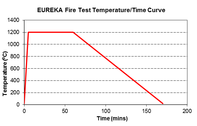
Figure 4 – RABT-ZTV (EUREKA) curve time-temperature profile
It should be noted that the latest version of the TSI (2014)7 makes no specific recommendation on fire load or size, which need to be assessed on a project-by-project basis. However, TSI (2014) requires the integrity of the structure to be maintained sufficiently long to permit self-rescue, evacuation and intervention, and also for a time to allow evacuation of any structures that would be impacted by a tunnel collapse.
To minimise potential fire load during operations, the actual potential fire loads within the Crossrail tunnels were assessed during the design phase and when specifying the new trains. The result was that use of the EUREKA curve was considered to be a conservative approach and there was no need to increase the fire load requirements of the main tunnel linings beyond the TSI (2008) requirement.
Project performance requirements
The designers responsible for the detailed design of each lining type specified the final performance requirements for the various structures. This included a combination of limiting spalling, limiting the maximum temperature reached by any reinforcement during the fire, and limiting any permanent loss of strength of the heated sections of concrete so that structural failure would not occur. The spalling limits set were 25mm for PCL, while for the SCL the limits were the loss of a nominal 50mm fire protection layer plus 25mm of the remaining lining. Reinforcement temperature limits were set at 4500C, which was higher than some design code general guidelines of 3000C, but the additional loss of strength was accounted for within the calculations of residual capacity of the linings.
Protection materials and mix designs
The introduction of monofilament polypropylene fibres within the concrete matrix has become common practice for tunnel linings subject to fire exposure, and testing has demonstrated that they can significantly enhance the performance of the material under fire conditions by limiting concrete spalling. The use of these fibres is also recommended within Eurocode 28, although the code is non-specific regarding quantities, particularly for higher intensity fires. The approaches taken for the use of this material within the structures depended upon the lining type, and summarised as follows:
- Segmental linings and cast insitu linings – polypropylene fibres incorporated throughout the full section thickness for both steel fibre-reinforced and traditionally reinforcement sections.
- Sprayed concrete linings – polypropylene fibres incorporated into a final layer of sprayed material (fire protection layer in figure 3). This layer was also considered to be part of the long-term load-bearing structure. A minimum thickness was specified by the designer at 50mm, but was subject to confirmation by testing.
Table 2 summarises the final mix designs for the segmental linings and table 3 contains summary details for the final SCL concrete mixes.
Table 2 – General PCL concrete mix details
Material Contract C300 Contract C305 Contract C310 CEM1 – Portland Cement (kg/m3) 287 337 258 PFA/GGBS (kg/m3) 123 113 172 20mm Limestone Aggregate (kg/m3) 643 723 263 10mm Limestone Aggregate (kg/m3) 684 361 706 Sand (kg/m3) 509 765 778 Steel fibre dosage (kg/m3) 35 30 30 Polypropylene fibre dosage (kg/m3) 1.25
(Propex 32 micron)
2.0
(Propex 32 micron)
1.5
(Baumhueter Eurofibre HPR)
w/c ratio <0.35 0.32 0.33 Table 3 – General SCL concrete mix details
Material Contract C305 Contract C410 & C435 Contract C510 Cement (kg/m3) 399 455 400 Microsilica (kg/m3) 52 50 52 Large aggregate – Limestone (kg/m3) 435 629 505 Small aggregate – Limestone (kg/m3) 435 – 590 Sand (kg/m3) 870 1168 580 Steel fibre dosage (kg/m3) – not in fire protection layer 35 35 35 Polypropylene fibre dosage (kg/m3)
Fire protection layer only.
1.0
(Propex 32 micron)
1.0
(Adfil Ignis)
2.0
(Propex 32 micron)
w/c ratio 0.4 0.36 0.43 Testing regimes
The final configurations and material selections for the PCL and SCL structures were required to be verified under large-scale fire testing to the specified EUREKA curve, with all tests undertaken under compressive load conditions representative of the loads on the structures in the works. The stresses applied to the test piece were representative of the worst case design working load stresses, plus the effects of stress increase due to lining expansion in the ground under elevated temperature conditions. Compression loads were applied to the samples to develop a stress level of approximately 15MPa in the PCL test pieces, and 5MPa in the SCL.
For the precast segmental lining tests, 300mm-thick curved members representative of the tunnel segments were used rather than flat panels. The test set-up was as shown in figure 5, and the stresses in the lining during the test were controlled by relaxation of the rams to compensate for the test segment expansion during the fire test. Deformation of the segments was also monitored during the test but this was found to be minimal and had no significant impact on the performance of the concrete under fire test conditions.
For the SCL tests, flat panel test samples with a total thickness of approximately 500mm were used, with the test undertaken under compressive loads as shown in figure 6. Most tests had a vertical panel arrangement rather than horizontal to suit the furnace equipment available, although horizontal test set-ups were also acceptable.

Figure 5 – Precast segmental lining test arrangement

Figure 6 – Test panel arrangement for representative SCL linings.
The test pieces included instrumentation and monitoring to measure the following during and after the test: loads (concrete stress); temperature in the concrete at various depths using thermocouples, and temperature in any reinforcement. Spalling depths were measured immediately after the test and after a cooling period for the samples.
Test results
It should be noted that the results of fire tests are very specific to the mix design and the particular polypropylene fibres used, and these results can only provide guidance for possible successful combinations on future projects unless similar mixes and material sources are used. The stress regime within the test samples can also influence performance and this should also be taken into account.
Spalling depths for the PCL test pieces are shown in table 4
Table 4 – Spalling depths from successful PCL fire tests
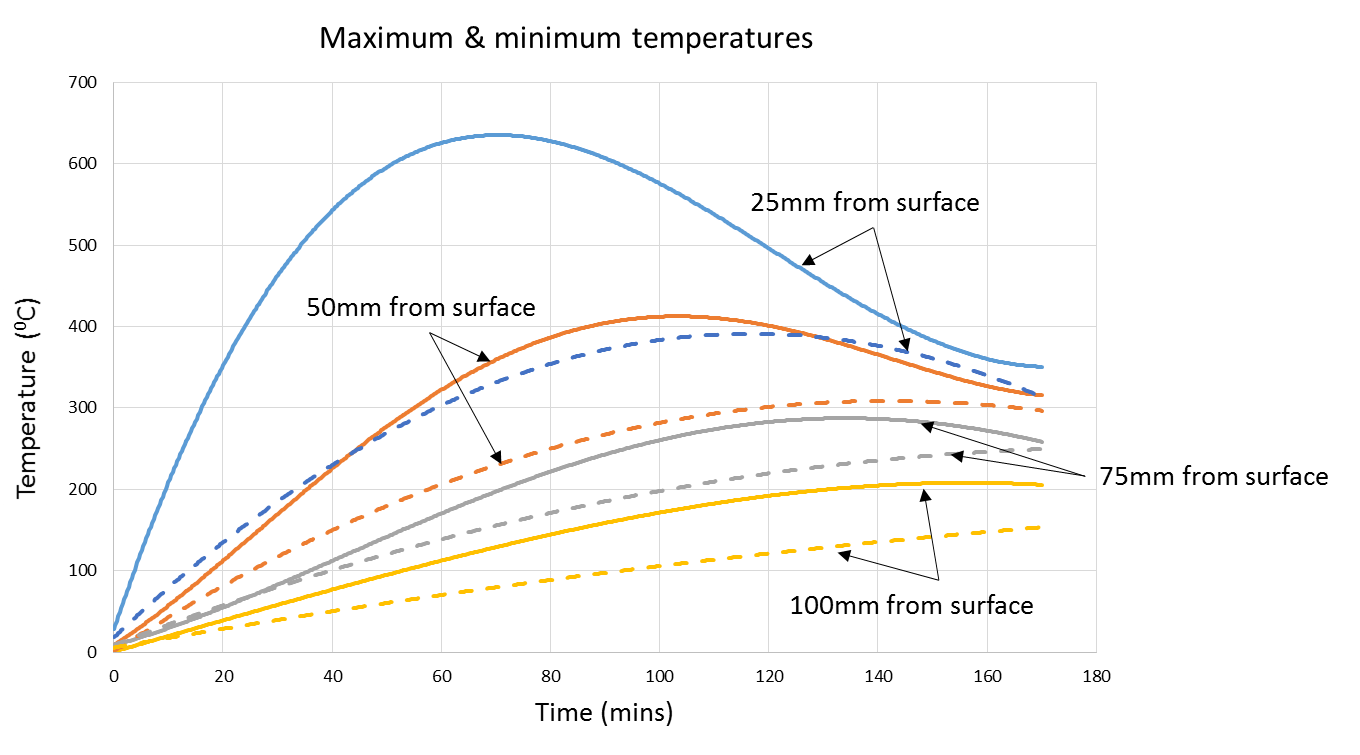
Measured spalling depths C300 C305 C310 Average spalling depth (mm) 16 8 3 Maximum spalling depth 23 13 14 Figure 7 shows smoothed lines for maximum and minimum temperatures recorded at depth in the concrete (referenced to the fire-exposed face at the start of the test) from all PCL test results. The maximum temperatures were recorded on one of the C300 tests where the 23mm spalling depth was recorded. The minimum temperatures were measured on a C305 test, and this was the same test that recorded the maximum spalling of 13mm on this contract. Other temperature results from tests on these contracts were similar and approximately midway between the extremes plotted on figure 7, with maximum temperatures recorded at about 4600C to 5000C at a depth of 25mm. C310 temperatures recorded during testing were closer to the maximum temperature curves shown in the figure.
Temperatures were measured using two thermocouples in each layer being measured, spaced at 500mm along the centre-line of the segment. Average values from all the successful tests were about 70-80% of the maximum values shown in figure 7.
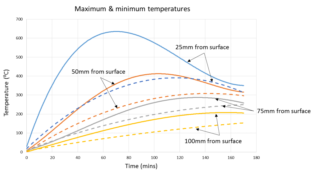
Figure 7 – PCL ‘Smoothed’ maximum and minimum temperature profiles with depth
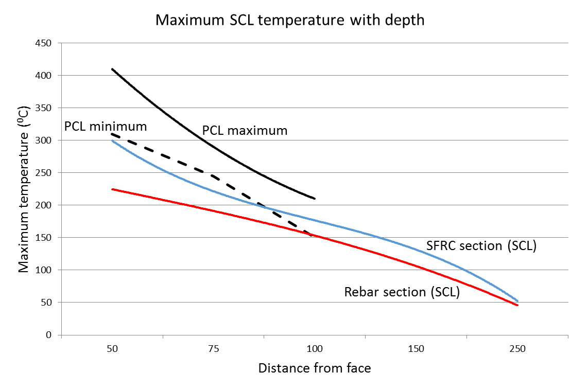
For the SCL tests it was necessary for the contracts to test two panel types – one with the secondary lining consisting of steel fibre-reinforced concrete, and another with a secondary lining consisting of plain concrete (no steel fibres) but with a representative quantity of reinforcing steel bars to simulate conditions at tunnel junctions and other reinforced sections.
Results from successful tests of temperature against depth within the SCL section are summarised in figure 8 where the maximum results from the tests are plotted for both the steel fibre-reinforced sections and traditionally reinforced sections, all with the polypropylene fibre fire protection layer sprayed at a minimum of 50mm. All distances are referenced to the concrete face exposed to the fire at the start of the test. For reference, both the maximum and minimum temperatures recorded from the PCL tests are shown.
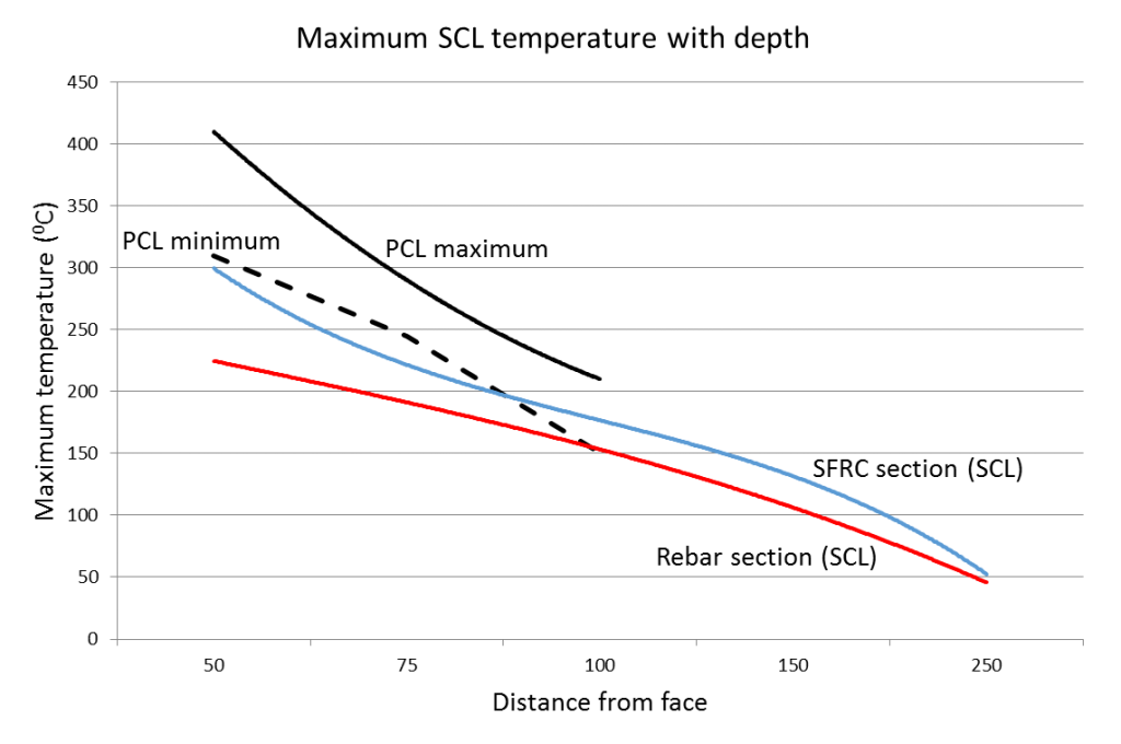
Figure 8 – SCL ‘Smoothed’ maximum temperatures with depth for EUREKA fire test
Additional tests were undertaken by various contracts during the project to demonstrate alternative arrangements for the linings and fire protection to suit particular construction circumstances. The following summarises the tests that met the specification criteria and which were accepted as solutions for the permanent works:
- C410 – 40mm polypropylene fire protection layer sprayed over steel fibre reinforced secondary lining (note that 40mm fire protection over reinforced concrete failed the specification criteria in 1 out of 3 tests and was not accepted) ;
- C510 – Light stainless steel mesh and anchors within the fire protection layer at 50mm cover to assist with profile control;
- C510 – secondary lining sprayed in two main layers (each layer nominally 150mm thick) with polypropylene fibres and steel fibres in the final 150mm layer. A separate 50mm fire protection layer was not provided, but local non-structural protection against snagging on potentially exposed steel fibres at the surface was required in some areas.
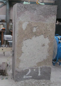
Generally there was more spalling and some delamination of the fire protection layer witnessed during the SCL test compared to the PCL tests, but the loss of the protection layer when sprayed as a final layer was acceptable for the design as long as spalling of the remainder of the secondary lining was less than 25mm. The majority of tests saw no spalling of the secondary lining although some spalling of up to 20mm was detected in a few panels.
Figure 9a shows the typical condition of the fire protection layer on a panel at the end of a test. Figure 9b shows the same panel at the end of the cooling phase, with a lighter area depicting where a zone of local spalling has occurred.
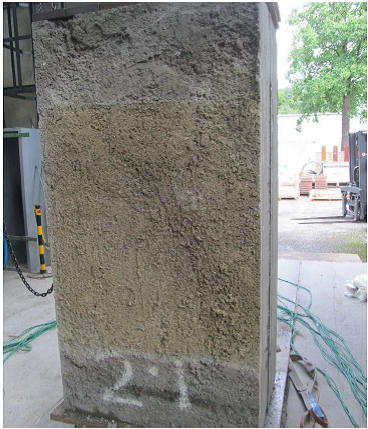

Figure 9a – Test panel immediately after test Figure 9b – Same panel after cooling Construction issues and resolution
During application of the fire protection layer onto the SCL there were some construction issues resulting in the need for repairs or an alternative strategy to demonstrate compliance with the TSI. The main issues were linked to a low bond between the fire protection layer and the sprayed secondary lining, or local areas of under-thickness of the fire protection layer itself.
Low bond strength and some delamination of the fire protection layer was noted during site verification testing which, against expectations, was almost entirely within the lower half of the tunnel. The fact that bond above axis level was found to be good led to the conclusion that there was likely to be some connection between the delamination problem and contamination of the surface of the secondary lining from dust. The time that the secondary lining was left exposed prior to spraying the fire protection layer varied from a few weeks to over a year with no discernible difference in the frequency of observed reduced bond.
Extensive cleaning of the secondary lining was undertaken prior to spraying the final layer at all times, and the time between the completion of cleaning and the start of spraying was considered critical. Improvements were made by introducing some modifications to the construction sequencing. This limited the exposure time between cleaning of the substrate and spraying of the final fire protection layer by reducing the areas sprayed at any time immediately after cleaning. However, despite limiting sprayed areas to 2m sections along the tunnel length and only half the tunnel invert prior to the next cleaning cycle, this was still not a complete cure for the problem.
There were also some localised areas of under-spray of the fire protection layer detected following full reconciliation of all surveys. These were mainly concentrated at the complex junctions between the cross passages and the platform tunnels, which were curved at the intersection to allow for the use of curved architectural panels around the junction, and presented survey and scanning problems during construction.
In the vast majority of cases any non-conformances were repaired using agreed techniques of removal and replacement, but during these on-going operations the project was running a risk that some required repairs might become difficult to achieve because of access problems behind cladding or other structures, or concerns over the safety of employees engaged in repairs in confined areas. For this reason the project developed an alternative justification strategy as a mitigation measure against potential access conflicts leading to delays.
The revised justification strategy required the theoretical analysis of a plain concrete section under the defined EUREKA curve fire conditions to be undertaken to establish the maximum likely extent of concrete spalling, assuming that there was no fire protection system in place. This was considered to be a conservative starting point given the actual condition of the SCL linings on site which were over 99% conforming; even non-conforming areas had some protection and were localised and relatively small. The framework consultant for the SCL design (Mott MacDonald) undertook a one-dimensional analysis of concrete temperature rise and spalling using a model validated against tests undertaken on a number of different concrete samples and a variety of different fire scenarios, including those detailed in references 9 and 10, and the Crossrail fire test results. This modelling demonstrated that in worst-case temperature rises, the maximum level of spalling under a EUREKA fire that might conservatively be expected would be between 120-150mm based upon conservative modelling assumptions. In addition, a revised analysis of the structural capacity of the remaining structural section following spalling was undertaken and demonstrated that in the most heavily loaded sections of the platform tunnels it would be acceptable to allow the complete secondary lining (minimum 300mm-thick section) to be ignored from the assessment and there would still be no structural failure of the remaining primary lining before suitable repairs could be completed. Based upon these assessments it was considered that local defects below axis could be accepted if repairs became impossible to undertake for any reason.
In the final condition following all repairs, there were only two small areas where repairs could not be completed, and these were in locations where there was an additional reinforced concrete structure protecting the tunnel lining from the fire source. Although not taken into consideration in any of the assessments, and not specifically designed to withstand the EUREKA fire exposure itself, this structure would also offer some protection to these areas.
Conclusions
The tests undertaken on the Crossrail lining samples demonstrate that the use of monofilament polypropylene fibres provides effective protection against spalling to the concrete even under extreme fire loads. The test results have demonstrated that temperature profiles measured through the concrete sections can vary considerably even under similar test conditions, with the lowest maximum temperature measured in the PCL tests being only about 65% of the highest temperature measured. Such high variability could influence the test result although interestingly a lower volume of polypropylene fibres was demonstrated as suitable on the PCL test with the highest measured temperatures.
A number of lessons can be taken from the Crossrail experiences and observations made during the spraying of relatively thin layers of SCL, in this case for the fire protection layer but these could also apply to the spraying of all thin layers. The main considerations for future projects would include the following:
- Survey and the control of the thickness of thin layers is difficult, particularly where there is complex geometry, and space proofing for the final layer needs particular consideration along with a more robust means of checking thicknesses. Even allowing for tolerances of +/-30mm on the fire protection layer in a normal tunnel cross-section proved to be challenging, with complex geometry introducing additional difficulties for scanning and analytical accuracy.
- Surface preparation is critical to achieving a good bond between the layers; a process using continuous cleaning with high pressure systems and ensuring smaller areas are sprayed is required. There are obvious programming issues with this requirement that need to be allowed for.
- Bond below axis has proved to be more difficult to achieve than the good bond observed above axis. This is thought to be at least partly related to the surface preparation and contamination of surfaces below axis.
References
- The Crossrail Experience – Bill Tucker and Mike Black. WTC 2016 San Francisco
- ICE Proceedings Special Issue Volume 170, Issue CE5 May 2017
- Crossrail Project – Infrastructure design and construction. ICE Publishing Volume 1 Edited by Mike Black, Christian Dodge and Ursula Lawrence
- Crossrail Project – Infrastructure design and construction. ICE Publishing Volume 2 Edited by Mike Black, Christian Dodge and Jessica Yu
- Crossrail Project – Infrastructure design and construction. ICE Publishing Volume 3 Edited by Mike Black
- European Technical Specification for Interoperability – Safety in Railway Tunnels (TSI-SRT) no. 2008/163/EC.
- European Technical Specification for Interoperability – Safety in Railway Tunnels. Commission Regulation (EU) No 1303/2014
- BS EN 1992-1-2: Eurocode 2: Design of concrete structures. Part 1-2 General rules – Structural fire design
- Hoj N P (1999) Great belt Tunnel, fire resistance and damage. Proceedings of the 1st International Conference on Tunnel Fires, Lyon, France May 1999
- Jansson R and Bostrom L (2008). Spalling of concrete exposed to fire. SP Technical Research Institute of Sweden, SP Report 2008:52
-
Authors

Mike King BSc CEng MICE - Crossrail Ltd
Technical and Compliance Director – Tunnels, CH2M