Pushing the limits of Secant Walling
Document
type: Technical Paper
Author:
Gareth Hales
Publication
Date: 10/11/2015
-
Read the full document
1. The Background

Figure 1 – Bond Street – Crossrail: Station Layout
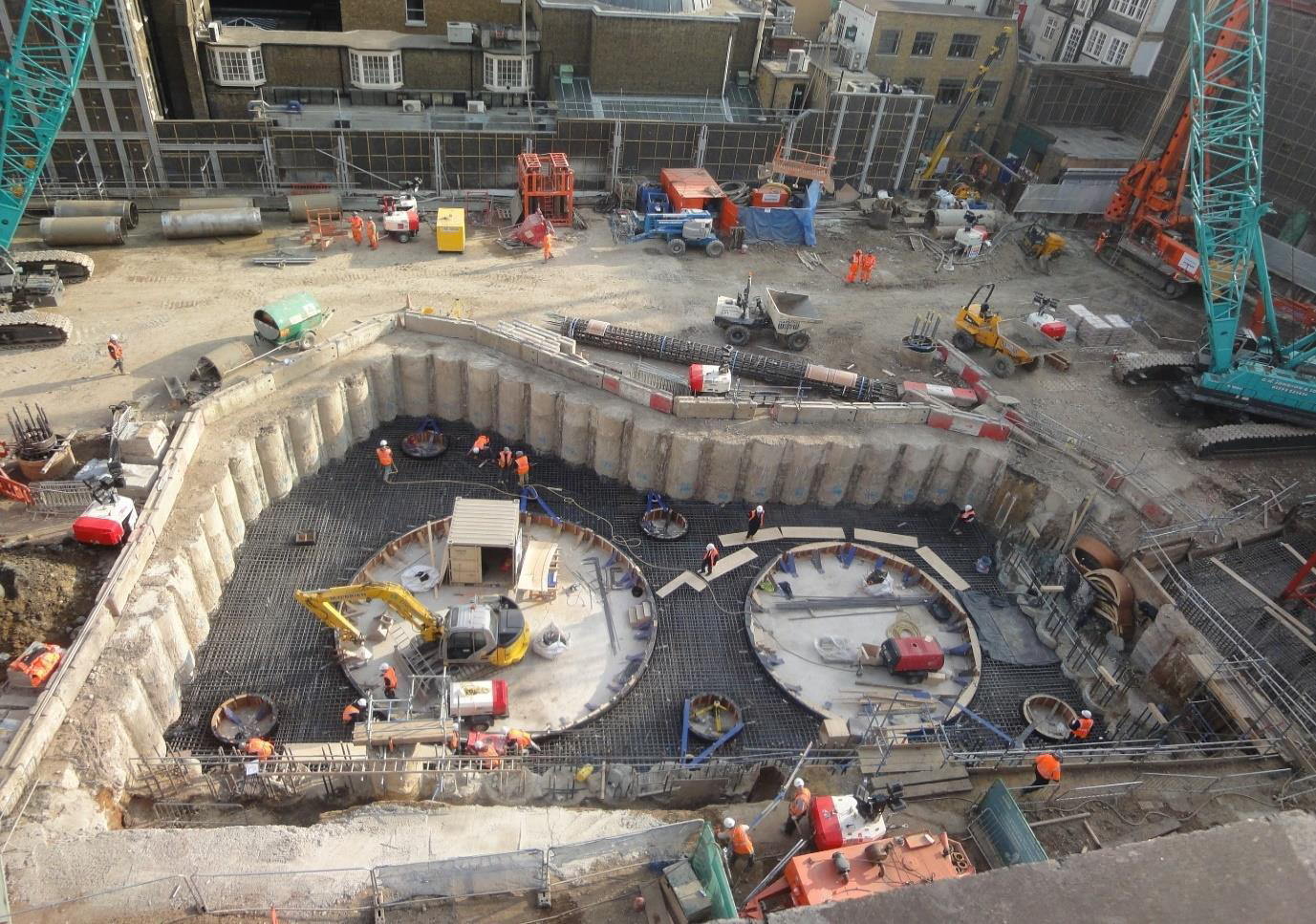
Figure 2: Bond Street Eastern Ticket Hall – North West Shaft – by day.
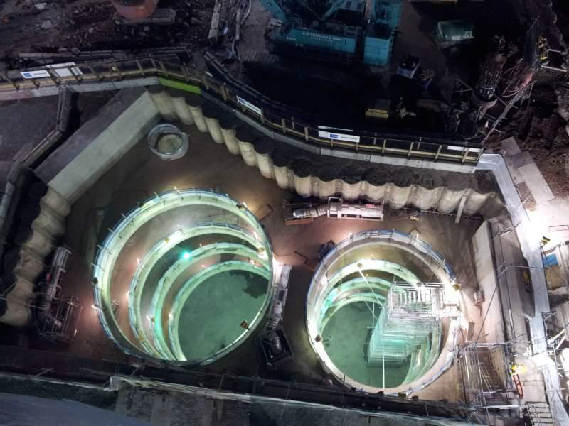
Figure 3: Bond Street Eastern Ticket Hall – North West Shaft – by night.
Costain-Skanska Joint Venture (JV) was awarded the £35m main contract for the construction of the Eastern and Western Ticket Halls. The scope included the construction of the Western and Eastern Ticket Halls including the installation of piling, diaphragm walling and plunge columns. Specialist piling contractor Cementation Skanska was awarded piling packages for both Eastern and Western ticket halls, with the main construction commencing November 2011.
The Eastern Ticket Hall
Bond Street Eastern Ticket Hall is located on the site of 18 & 19 Hanover Square. The site is bounded to the east by Hanover Square, to the north by Tenterden Street, to the north-west by 1 Tenderton Street, to the south by 20 Hanover Square and to the west by Dering Yard. A number of buildings fronting the Square, including numbers 20 & 21 adjacent to the Eastern Ticket Hall site are listed. Numbers 20 & 21 are Grade II listed. Number 20 Hanover Square is a substantial terraced town house dating from 1710. Just your typical City of London site.

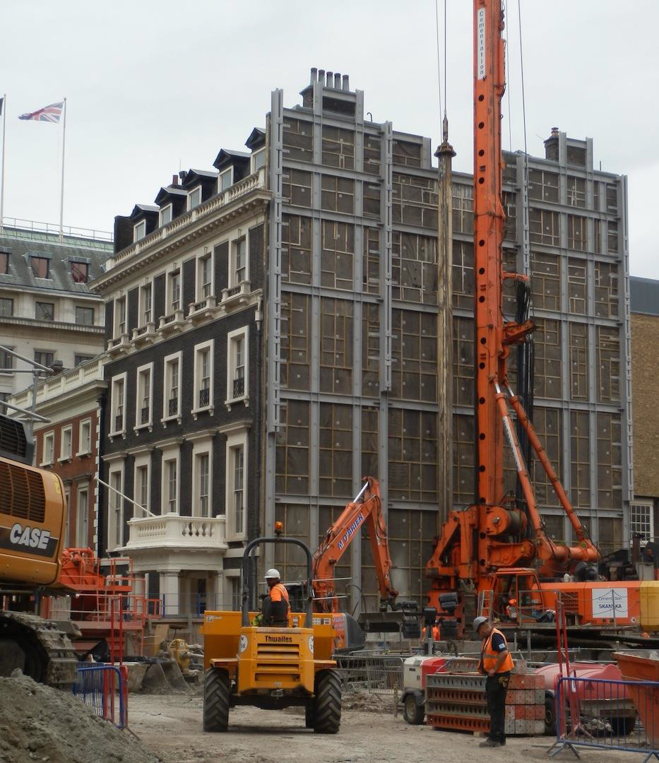
Figure 4: Up close and personal with Nr 20 Hanover Square
2. Geotechnical Design
The principal structural elements of the Eastern Ticket Hall were:
- A deep box extending from ground level down to the platform level – about 27m below ground floor, with perimeter walls propped by the internal slabs acting as props, and founded on piles and a raft slab at platform level.
- An escalator link from ground level to platform level which starts inside the deep box and then protrudes outside to the west to meet cross passages at platform level.
- A vent shaft rising to approximately 30m above ground and starting at level B-4.
- Running tunnels and platforms with associated cross linking passenger passages and service tunnels.
Ground Profile
The ground profile for the Eastern Ticket Hall can be summarised in the table below:
Stratum Revised Design Values Top of Stratum Thickness (mATD) (m) Made Ground 124.0 4.0 Terrace Gravel Deposits 120.0 3.0 London Clay (Division A3) 117.0 17.0 London Clay (Division A2) 100.0 11.0 Lambeth Group Upper Mottled Beds 89.0 6.5 Laminated Beds 82.5 1.0 Lower Mottled Beds 81.5 7.5 Upnor Formation 74.0 3.8 Thanet Sands 70.2 1.2 Chalk 69.0 EOH EOH = end of hole
Given the general site and ground conditions present on the project, together with the construction requirements, large diameter rotary bored segmentally cased secant piles were considered the most appropriate in terms of minimising the environmental impact.
Temporary secant piled retaining wall design
The analysis was carried out using the computer programme WALLAP. The calculations were carried out using the strength factor method with factors on actions and resistance in accordance with BS EN 1997 – 1:2004 (Eurocode 7).
The design is based on 1300/1200mm diameter male piles at 1500mm spacing with 750mm diameter female piles.The WALLAP analyses carried out by WSP for design of permanent secant wall piles were used to form the basis of the temporary secant wall design. The analyses were modified to reflect the surcharge loading conditions to which the temporary walls would be subjected, since the temporary wall piles are within the station box (i.e. entirely within the permanent secant piled perimeter).
The piling works for the eastern ticket hall required the installation of:
- 220 linear metres of permanent perimeter secant piled retaining wall
- 45m of temporary secant piled retaining wall
- 25m of temporary contiguous piled retaining wall
- 69 large diameter bearing piles (26 of which were constructed with plunge columns to facilitate top down construction)
Male secant piles and contiguous piles were constructed using 1300mm diameter segmental casing. Where the male piles were founding below the base of the London Clay formation, they were constructed under bentonite support fluid, otherwise they were constructed dry, ie without the use of the support fluid.
Female secant piles were constructed as 750mm diameter Continuous Flight Auger (CFA) piles to an average depth of 20m. Concrete mix was a P280 soft mix. Failure to delay the strength increase of the concrete would have increased deviations problems with the augers during the construction of the male piles. Typical strength of the P280 at 28 days was 16N/mm2.
Figure 5: Construction requirements of the male secant piles pushed the boundary
Specified Tolerances
During the construction of the works strict specification tolerances had to be adhered to as detailed in the contract specification. The secant wall tolerance required a vertical tolerance of 1 in 200 over the cased length and 1 in 75 below the cased length, together with a positional tolerance of +/- 25mm.
The maximum permitted deviation of the finished plunge column from the vertical was 1:400 with a position tolerance at commencing surface of +/- 10mm. Plunge column twist tolerance angles was +/- 2.5 degrees. These strict tolerances on the plunge columns were achieved using Cementation Skanska instrumentation rig, CEMlock. Ref to Figure 6 below.
The tolerances were achieved by a number of standard practises adapted by Cementation Skanska, a Guide wall was installed prior to the secant piles being constructed. This helped ensure that the pile tolerances could be achieved throughout the pile installation. In additional, computerised rig instrumentation allowed pile verticality to be monitored during the digging process. Furthermore, all personnel involved in the piling works were clearly briefed on the latest contract Inspection and Test Plan (ITP) so that all roles and responsibilities could be clearly defined.

Figure 6: Elevation profile of CEMlock beam used for Plunge Column installation
3. Cycle Time Analysis
Due to specification requirements, the maximum period for the construction of the male secant piles was not to exceed 48 hours. With the site team working a double shift period of 20 hours per day in a 5 day week, detailed cycle times were compiled for the three varying male piles lengths: up to 47m in length, >47m – <52m in length piles >52m in length
The detailed cycle times allowed the site team to not only programme more accurately the material deliveries and required sequence of the piles it also allow the client to have a clear understanding of the works being carried out each day so progress could be monitored.
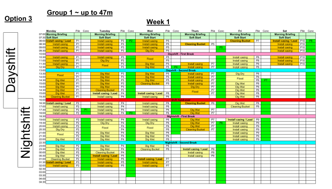
Figure 7: Example of Cycle Time Analysis
4. Reinforcement Cages
One of the greatest challenges of the project (apart from the logistics and programming) was the fabrication, handling and installation of the unusually, complex and heavy reinforcement cages required for the permanent Secant Piles.
Overall reinforcement cages were up to 44m in length and weighed up to 23t.
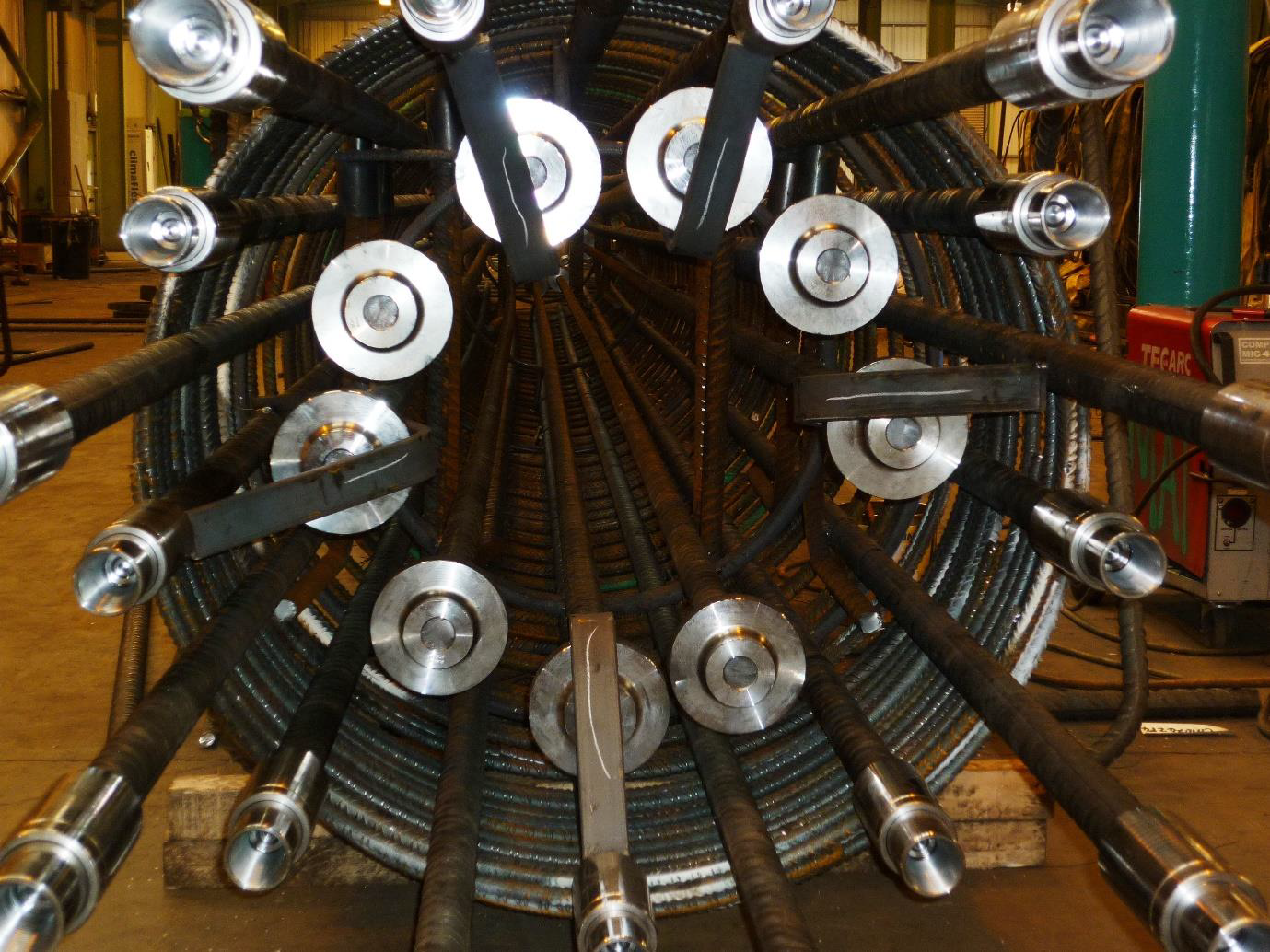
Figure 8: Typical cross section of a typical reinforcement cage for the male piles
The required couplers, terminator plates and internal cage made this one of the most challenging cages Cementation Skanska has produced over recent years. A high degree of skill was not only required to fabricate the cage, but also to assemble the cage on site. In addition to complying with both internal and external quality procedures, the cage was subjected to four levels of checking to ensure that it was constructed to the required specification and quality.
5. Plunge Columns
26Nr of the 69Nr large diameter piles required plunge columns to be installed after the construction of the piles. Plunge column lengths ranged from 9.5m to 34.5m with the universal columns (UC’s) being typically 356 * 406 * 634’s. The total weight of the column assemblages varied from 10t up to 25t.
Cementation Skanska were responsible for the design of the permanent splice between column sections. A typical splice connection is shown below in Figure 9
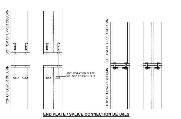
Figure 9: Typical plunge column permanent splice detail
6. Close Working Relationship
Clear lines of communication are essential on any large construction project and Bond Street was no exception. It was imperative that CSL had clear lines of discussion with both the main contractor and supply chains partners.
One key element of clear communication with CSJV came in the form of the 07:30 morning meeting. Each morning the required parties from both companies would sit down and discuss events from the previous day and forward plan the details of the coming days. This level of discussion meant that the required planning and safeguards could be put in place to ensure that the programme targets could be achieved.
Communincation between Cementation Skanska and their suppliers was another critical element of the works. A full time engineer was based at the fabrication factory of the reinforcment suppliers Romtech. This helped ensure that the latest information was being feedback to those working on the fabrication floor. It also meant that any issues could be flagged up early and dealt with before the cages were delivered to site.
The foregoing are not examples of new and immovative ways of working, merely an enhancement of previous methods learned from other contracts that ensured lines of commincation were as effective as possible.
7. Conclusion
The technical challenge of the secant male cage design, the limits of the piling equipment pushed during the installation of the segmental casing and the complexity of the piling sequence with the just in time cage deliveries, resulted in Bond Street ETH being one of the most challenging geotechnical projects that Cementation Skanska had undertaken in recent years.
Ultimately the end product of a secant wall which was delivered safely, on time and budget, and with no remedial leak sealing required during the excavation period of the shafts speaks volumes for the effort that was put in by all the personnel involved.
-
Authors