Rehabilitation of a Victorian Railway Tunnel for Crossrail
Document
type: Technical Paper
Author:
David Wilde BSc, CEng, MIStructE, MICE, Jonathan Craft BSc, MSc(Eng), DIC, CEng, MICE, ICE Publishing
Publication
Date: 07/09/2015
-
Read the full document
Keywords
Tunnels & tunnelling; rehabilitation & renovation; brickwork & masonry
List of abbreviations / notation
OHLE overhead line equipment
CRL Crossrail Ltd
DLR Docklands Light Railway
LUL London Underground Limited
ATD above tunnel datum
CFA continuous flight auger
ID internal diameter
CEDS Crossrail Engineering Design Standards1. History
The Connaught Tunnel, designed by Sir Alexander Meadows Rendel (son of the founder of the eponymous firm of engineers), is located in London’s historical Docklands to the east of the City and is beneath the navigation channel (hereafter called the “Dock Passage”) between the Royal Victoria and Royal Albert Docks (ref. Figure 1). The rail tunnel was built in 1878 by cut-and-cover methods[1] and is formed of brickwork arches on beds of mass concrete. The longitudinal profile of the tunnel and approach cuttings is shown in Figure 2. The dock passage was deepened during 1933 – 1937[2], to accommodate ships of greater draught. This involved the strengthening of the existing twin brickwork tunnels under the passage with cast steel linings and the removal of brickwork above the tunnels. The passage was also widened to accommodate shipping of 24 m beam which involved the partial removal and replacement of the south dock wall using a combination of sheet piles and a relieving platform, with the works being completed in 1959[3].
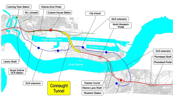
Figure 1 – Crossrail South-East Spur and Location of the Connaught Tunnel
Goods services were withdrawn from the railway in 1970 and the Royal Docks closed to commercial traffic in the 1980’s.With the expansion of the DLR and the opening of a dedicated station for London City Airport in 2005, passenger services on the North London Line ceased in 2006.
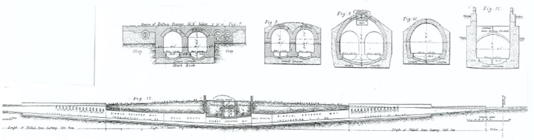
Figure 2 – Longitudinal Profile and Typical Cross-sections of Connaught Tunnel
The Crossrail Act of 2008 incorporated the tunnel into the south-east branch of the new Crossrail line between Custom House Station and North Woolwich Portal. Network Rail remained responsible for maintaining the tunnel until the Crossrail programme of works commenced in 2012. The programmed date for Civil Works Completion is May 2015.
2. Ground Conditions
Given that the tunnels were built in open cut the ground immediately adjacent to the tunnels consists of backfill materials of variable consistency. Beyond the cut however, the geology surrounding the Connaught Tunnel comprises Made Ground overlying Alluvium, River Terrace Deposits (Upper Aquifer) and Lambeth Group deposits (ref Figure 3). Measured groundwater levels in the Upper Aquifer (River Terrace Deposits) are between 97 mATD and 100 mATD (approx).The tunnels would appear to have been founded on very stiff clayey (i.e. impermeable) horizons within the Lambeth Group. Underlying the Lambeth Group is found the Lower Aquifer comprising the Thanet Sands and Chalk. Piezometric levels in the Lower Aquifer are between 85 mATD and 88 mATD. The individual soil types are described in Table 1.
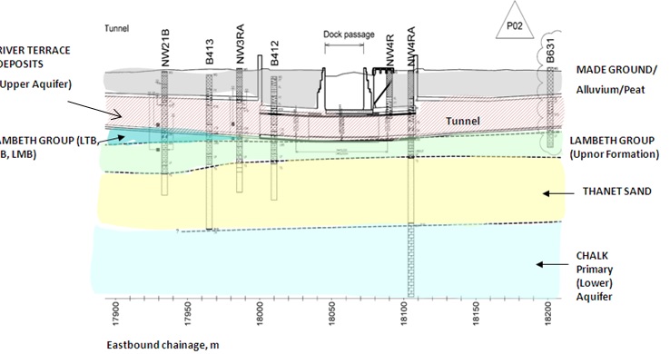
Figure 3 – Geology of Connaught Tunnel
Soil Type Top Level (mATD) Thickness (m) General Description Made Ground 105 to 106 6.9 to 7.6 Slightly clayey to clayey sandy gravel to gravelly sand with some reworked soft Alluvial material. Gravel is sub-angular to rounded, fine to coarse to (rare) cobble size brick, track ballast, slag, flint and concrete. Alluvial Deposits 98 to 99 2.1 to 5.4 Very soft to soft, locally firm, organic rich CLAY and SILT with layers and lenses of amorphous to fibrous PEAT up to 4.0m thick. Locally slightly sandy to sandy. River Terrace Deposits 96 4.6 to 0 Medium dense to dense brown sandy locally very sandy angular to sub-rounded fine to coarse GRAVEL of flint. Sand is fine to coarse. Lambeth Group 92 to 93 8.8 to 9.1 Stiff to very stiff slightly sandy CLAY with occasional shelly pockets. Thanet Sand 83 to 84 15.9 Very dense, light brown grey fine and medium SAND. Chalk 68 Table 1 – Ground conditions adjacent to and beneath the Connaught Tunnel (based on borehole information
3. Existing Structures
The running tunnel comprises Eastern and Western approach ramps in retained cut, of lengths 267 m and 293 m respectively, Eastern and Western arched brick-lined twin track single tunnel sections of lengths 220 m and 222 m respectively and a Central twin track tunnel section beneath the dock passage of length 107 m.
Ancillary structures consist of two ventilation air shafts located either side of the Dock Passage at the ends of the central tunnel section, and a pump sump shaft and Headhouse located on the northern side of the dock passage.
3.1 Approach Ramps
The approach ramp retaining walls are of mass concrete construction. The walls at the top of the ramps are gravity structures and embedded approximately 3 m below track level. A concave mass concrete invert exists further down the ramps and this extends as far as the Single tunnel sections. The deeper sections of the cuttings are propped by high level mass concrete arches. These concrete arches were formed using brickwork centring.
3.2 Single-arched Brick-lined Twin-track Single Tunnels
The portals to the single tunnels are of mass concrete construction. The concave invert of each Single Tunnel is formed of brickwork founded on mass concrete. The brickwork tunnel lining is 7 brick rings (i.e. c.900 mm) thick and the side walls are haunched externally and formed of a 900 mm (typical) thickness of mass concrete battered down from the crown. Puddle clay was applied to the outside of both (i.e. East and West) Single Tunnels to provide some resistance to water ingress.
Each single tunnel widens as it approaches the twin tunnelled central section thus forming a bellmouth. The headwalls have been constructed in brickwork which supports the brickwork ventilation shafts above. The shafts are 2.4 m diameter and the base of each is 8.7 m below ground level with a further 4 m projecting above ground.
Bomb damage occurred to the Connaught Tunnel in September 1940 which required a repair approximately 10 m long by 5 m deep to the eastern single brick arch tunnel haunch above the future Eastbound track.
3.3 Central Twin Single-Track Tunnel Section beneath the Dock Passage
The twin tunnels were constructed in brickwork with a 600 mm thick wall separating the two tracks. The inverts were built with a brick lining on a mass concrete base. The sections of tunnel both sides of the dock passage are haunched with concrete over the crowns of the twin tunnel.
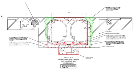
Figure 4 – Existing Twin Tunnels under the Dock Passage
The section under the Dock Passage was built as a brickwork box containing two service tunnels to the west and one to the east (ref. Figure 4). The side walls below the level of the service tunnel are approximately 1.6m thick. The crown brickwork thickness was reduced from 1.35m to 0.45m during the Dock Passage deepening works of 1933 -1937, in preparation for which the existing brick tunnels were reinforced with a bolted cast steel lining.
The north dock wall above the tunnel is a substantial gravity retaining wall of mass concrete constructed at the same time as the tunnel. The south dock wall directly over the tunnel consists of an earth berm (or limpet) at the toe of a shallow sheet pile wall with a suspended deck structure above[3].
3.4 Headhouse, Pumpshaft and Drainage
The original track system was ballasted. A gravity drainage pipe was installed within the ballast. The pipework drained towards the tunnel nadir which was located in the Central Single Track Twin tunnel section beneath the dock passage. The nadir was connected to the pump shaft by a horseshoe shaped brick culvert. The pump shaft provided the sole drainage pumping facility for the tunnel and approaches with the discharge being pumped into the adjacent Royal Albert Dock. The existing Headhouse consisted of single storey single leaf brick building with a timber roof, built over the pumpshaft.
4. Design
The C315 Connaught Tunnel works package includes all the works required to render the existing Connaught Tunnel structure suitable for use as part of Crossrail. This includes modification and strengthening of the approach ramp structures on either side of the tunnel, renovation / reconstruction of the tunnel sections, provision of drainage systems and a deepened pump sump shaft.
4.1 Functional Requirements
The relevant Stakeholders concerned with the Connaught Tunnel are Network Rail, London Underground and Rail for London. The Crossrail Programme Functional Requirements outlines the basic Stakeholder requirements for the new railway which are a) to ensure a minimum line speed of not less than 65 kph using the CRL Gauging Standard and, b) to provide safe evacuation routes. Surveys carried out during the preliminary design phase demonstrated that the existing tunnel has insufficient headroom to accommodate the proposed design swept envelope and OHLE train systems even after the removal of the track ballast. Therefore at best the existing brickwork / mass concrete invert has had to be lowered and in some sections broken out and replaced with reinforced concrete.
4.2 Crossrail Engineering Design Standard (CEDS) Requirements
The purpose of the Crossrail suite of standards is to ensure that a consistent design approach is taken throughout the project. The basis of the standards is provided by Eurocodes or other recognised Codes of Practice. The Design Life of the permanent structure is 120 years. The structural grade of concrete used for new works is C32/40. Micro synthetic fibres have been incorporated in the concrete mix to reduce the likelihood of spalling, and an assessment carried out on the new concrete has confirmed that the requirements of RABT-ZTV (EUREKA) fire resistance profile curve would be met. Railway loads based on BS EN 1991 Part 2, load model LM71, have taken into account longitudinal distribution and dynamic effects. A construction load allowance of 20 kPa has been assumed throughout. Flotation checks have been based on a flotation factor of 1.1 using a concrete density of 23 kg/m3. The design limits for crack widths for new works and water ingress above axis level have been set respectively at 0.3 mm and 0.13 l/day/m2 overall or 0.24 l/day/m2 below axis level.
4.3 Approach Ramps
4.3.1 New Invert Structure
The proposed direct fix track system requires a track support slab. The first 107 lin.m and 122 lin.m of the Eastern and Western approach ramps respectively consisted of ballast on Fill which required replacement. The maximum allowable settlement of the slab under LM71 rail loading could not exceed 15 mm without compromising the rail fixings. The new track support slab is formed of 450 mm thick reinforced concrete providing a 500 mm deep zone above for the new track system. The slab to the Western Approach was originally to have been founded on 600 mm of compacted 6N granular fill but as a result of value engineering – following additional ground investigation – it was determined that the slab could be founded directly on the insitu dense sands and gravels of the River Terrace Deposits. Apart from the resulting cost and programme benefits, this had the additional technical merit of not having to undermine (albeit sequentially) the existing gravity retaining walls which would have necessitated slow (therefore costly) “hit-and-miss” construction including the provision of extensive propping. Ground investigation on the Eastern Approach proved that the ground had a lower bearing capacity than the Western Approach and it was necessary therefore to install 600 mm diameter CFA piling at grid spacings of 1800 mm to support the track support slab here. Anti-flotation weepholes through the new invert slab are provided at 1800 mm centres along the centreline of the invert to relieve groundwater pressures.
4.3.2 Appraisal of existing structure
The existing walls were appraised for resistance to earth and water pressures due to external flooding. Trial pits demonstrated that the mass concrete walls are embedded approximately 3m below the existing track level and core results demonstrate a thickness of 1.2 m to 2.2 m. It was determined that while the walls could resist existing earth pressures they would fail if floodgates were to be placed across the approaches. Strengthening works would have required a new structure to be placed outside the line of deviation set by the Crossrail Act of 2008. It was subsequently determined therefore, that the walls would remain stable provided that floodwater could be allowed to overtop the rail levels at the commencement of the approaches.
The existing ballast and drainage system was removed following the installation of a temporary drainage system. The existing concave invert has been trimmed to suit the requirement for the new track system and vertical clearance for the OHLE under the arches. The walls and residual invert were appraised on the basis that the latter provided a prop at the base of the walls. The existing invert, in conjunction with the retaining walls, was checked for flotation and it was concluded that no weep holes were required to ensure long-term stability against uplift.
4.4 Single-arched Brick-lined Twin-track Single Tunnels
4.4.1 Investigation and appraisal
The existing invert slab has to be partially trimmed to accommodate the final alignment, design train envelope with OHLE and a new invert track slab. A series of cores at 20 m centres was drilled adjacent to the centreline of the existing tunnel, avoiding the existing drainage system. These were used to determine the thickness of the existing invert and material strengths. The minimum core compressive test result recorded for brickwork was 16 MPa and following the application of material and partial load factors the working capacity was determined to be 3.2 MPa. Core compressive test results from concrete samples were assessed on the basis of BS EN 13791 and BS EN 1992 and a working capacity of 10.3 MPa was established.
The analysis of the existing tunnel was based on the use of a pole and ray force diagram and funicular polygons to establish viable compressive thrust lines throughout the masonry tunnel structure and to establish the compressive stresses. The model assumed a vertical half arch hinged about the centrelines of the invert and crown (see Figure 5). A spreadsheet was developed for this non stiffness based analysis and largely replaced the need for hand calculations. The appraisal was carried out using LUL Engineering Civil Engineering- Bridge Structures Standard 1-051 (as required by the notes under LUL Standard 1-053 Section 1.6). The initial checks were carried out on a 1m length of tunnel.
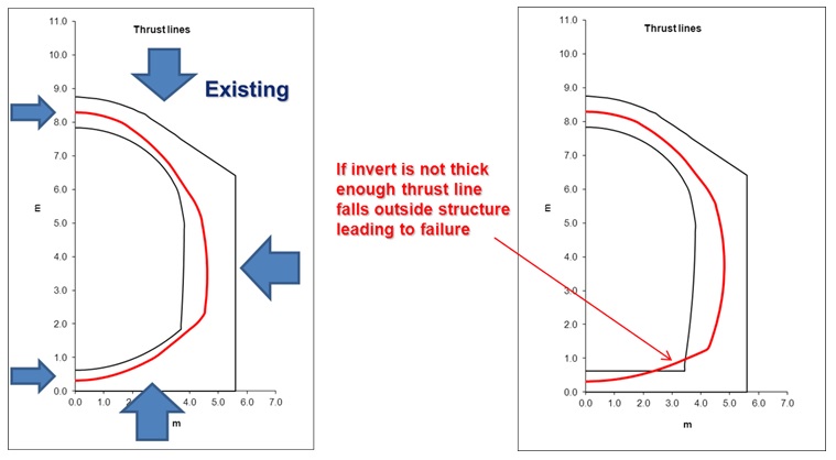
Figure 5 – Thrust line model for existing structure
Based on this initial analysis, it was determined that the re-profiled invert would have had insufficient capacity for 40 m from the western end of the Central Section and 135m from the eastern end. These lengths therefore required replacing. Where the invert did not require replacement, the existing brickwork was trimmed to the designed profile using a roadheader.
The extent of the invert replacement in the eastern single tunnel was later decreased from 135m to 76m by raising the vertical track alignment and altering the permanent way form to maintain the thrust lines within the existing brickwork.
4.4.2 Invert replacement
The reinforced concrete replacement consisted of 700 mm thick invert slabs with approximately 900 mm thick side walls. The thickness of the side walls corresponded to the thickness of brickwork to be removed whereas the invert thickness was reduced as far as possible to minimise excavation and the extent of dewatering required. In order to minimise the temporary works and therefore the risk of collapse during construction, the invert was built in 2.5 m bays with waling beams and horizontal props on both sides of the bays.
4.4.3 Bomb damage
The strength of the concrete originally used to repair the bomb damage exceeds that of the brickwork therefore only local repairs are required. These will consist of the local removal of the concrete and corroded reinforcement and replacement with new concrete. Grouting will also be required at locations where water ingress is occurring. The works will be carried out in bays to avoid the need for temporary propping.
4.4.4 Ventilation shafts
Ventilation in the tunnel is currently achieved through two existing brick lined ventilation shafts. The shafts are centrally positioned along the tunnel at the end of each bell mouth. They are located 107 m apart at either end of the former twin tunnel section and are approximately 2.4 m ID. These will remain as part of the refurbished tunnel as no forced ventilation is envisaged. With a length of 550 m, the Connaught Tunnel is not considered a ’long tunnel’ and therefore falls within exceptions for forced ventilation. The ventilation shafts are also to be used to accommodate ducts for low voltage electrical supplies and communications cabling. Access is required for maintenance and this will be achieved from the top of the shaft during Engineering Maintenance hours to minimise the impact on the operation of the railway below. The shafts have been inspected and repaired as part of the contract.
4.5 Central Single Twin-track Tunnel Section under Dock Passage
The new central section tunnel comprises a single twin-track reinforced concrete box to accommodate the design train envelope plus OHLE. This is the most complicated section of the project requiring a variety of construction techniques to realise the final product. Although the design of the end product is common, there are two basic sub-sections defined by their construction method (ref Figure 6): 1) beneath the dock walls where mining methods were required, and 2) beneath the Dock Passage where temporary cofferdams were installed to enable the existing tunnels to be broken out and the roof of the new structure to be built conventionally.
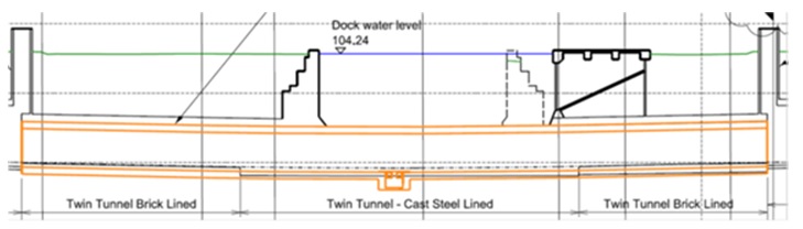
Figure 6 – Central Tunnel – Longitudinal Section
4.5.1 Loading
The box was designed to accommodate lateral soil, groundwater and superimposed pressures which are accommodated in bending by the tunnel walls. The roof and invert slabs act as struts to resist the forces at the top and bottom of the side walls. Vertical soil, groundwater and superimposed live loads due to access and OHLE etc. are supported by the roof and the roof support forces are transferred in compression through the walls and onto the invert slab where they are dispersed into the ground. The walls also support line-wide services. The invert slab is also required to accommodate uplift due to water pressure, superimposed dead loads due to the trackform and superimposed live loads from trains.
The CEDS requirement for possible future development of a minimum surcharge load of 75 kPa has been incorporated in the design. This exceeds the construction load allowance of 20 kPa above the below ground sections of tunnel both sides of the dock passage.
The roof structure of the dock passage has been checked with a superimposed load of 50 kPa in addition to the dock water to allow for the possibility of a ship sinking in the passage.
4.5.2 Water-tightness
Construction joints were detailed in accordance with CEDS for watertightness and were provided with hydrophilic strips, re-injectable water stops and water bars.
4.5.3 Flotation
The below-ground structure on both sides of the Dock Passage was checked at flood levels and the structure performed satisfactorily. The structure below the docks was checked on the basis that the Royal Albert Dock gates failed accidentally and the dock water level dropped by 7.1 m in line with the lowest tide level of the River Thames. In this case the structure had insufficient dead weight and it would be necessary to mobilise the existing brickwork structure on both sides of the box, which proved adequate.
4.5.4 Design Constraints
The walls are 1 m (nominal) thick and the roof and invert slab are 800 mm thick throughout. The top corners of the box are haunched to remain as far as possible within the confines of the existing twin tunnel brick-lined structure where the alignment passes beneath the dock walls. Regardless of location, all side walls were installed in situ (ref Construction Sequence shown in Figure 7) incorporating couplers to facilitate reinforcement continuity with the roof and invert sections.
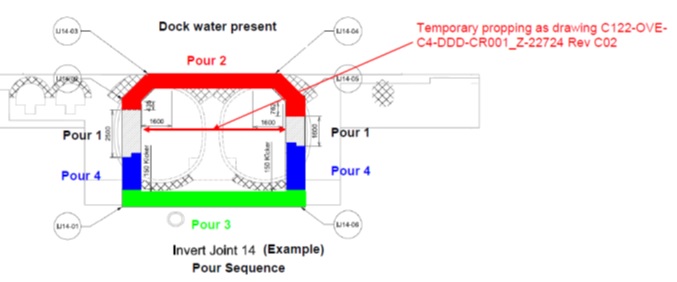
Figure 7 – Central Tunnel Typical Section
4.5.4.1 Beneath Dock Walls
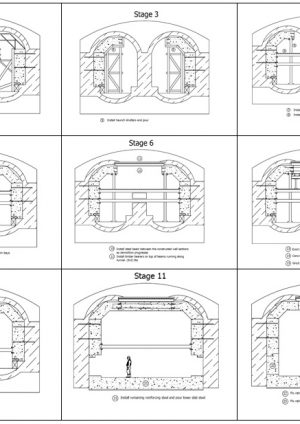
Having cast the side walls of the new box structure, it was necessary to install temporary propping between them which in turn necessitated coring through the existing central load-bearing brick wall. The crown could then be broken out piecemeal and the new tunnel roof cast in sections. This work has been carried out using crown bars and temporary props to support the dock wall structure during breakout of the existing masonry / brickwork. The invert had to be lowered throughout the central section of the tunnel and this was achieved in bays of 4.3 m width on a hit-and-miss basis to preserve lines of thrust through existing invert brickwork and mass concrete (ref Figure 8).
4.5.4.2 Beneath Dock Passage
The scheme designed was based on the requirement to maintain shipping access through the dock passage, therefore it was envisaged that the existing twin tunnels would be modified by temporarily infilling them with foam concrete then mining out an enlarged profile tunnel between the ventilation shafts, to install a pre-cast “binocular” lining that would accommodate twin tracks. The lining was to be protected from shipping in the dock passage using a 1m thick reinforced concrete slab cast on the dock bed. Subsequent investigations revealed that the thickness of the existing twin tunnel crown brickwork been reduced in the 1930’s to a far greater extent than shown on archive drawings which posed a greater safety risk. The requirement to maintain shipping access was therefore reviewed and a limited closure period was negotiated with stakeholders to enable the construction of a cofferdam and the construction of an alternative form of tunnel lining. The cofferdams enabled break-out of the crown from the top and construction of the roof of the new tunnel more conventionally and in larger bays than would have been possible from inside the existing tunnel. This resulted in real benefits to the programme. Once the roof was closed and sealed against the existing dock wall structures, the Dock Passage was reinstated and re-opened to shipping. The inverts were then lowered piecemeal beneath the newly constructed roof in sequence with the adjacent Dock Wall invert-lowering operations.
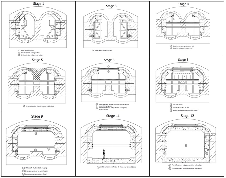
Figure 8 – Central Section Construction Sequence
4.6 Drainage, Pump Shaft and Headhouse
4.6.1 Drainage
The new drainage system was designed to accommodate surface run-off from the ramps due to rainwater, groundwater leakage, and discharge from the fire hydrants. The scheme was designed for storm rainwater flows based on a 1 in 1000 year return period. Channels are to be incorporated into the second stage trackform concrete to discharge the flows from the commencement of the approaches to a new nadir sump in the Central Section under the dock passage. The Central Section nadir sump is connected to the pump shaft by means of 600 mm internal diameter concrete pipe adit which was jacked from the pump shaft. The pipes incorporated stainless steel reinforcement and collars in order to comply with the 120 year design life requirement.
4.6.2 Pump Shaft
The existing pumpshaft needed to be deepened by 7m in order to provide sufficient capacity to cope with peak rainfall conditions. This required the removal of the existing Headhouse, shaft access steelwork and base. New 4.5 m diameter 200 mm thick precast concrete segments were installed by underpinning methods. The base of the shaft comprises a 600 mm minimum thick reinforced concrete slab.
4.6.3 Headhouse
The existing Headhouse – an octagonal Victorian brickwork structure – provided insufficient space to accommodate the requirements of a modern pumping facility. It was therefore, surveyed before being removed piecemeal for reconstruction elsewhere. Not all the materials were salvageable however as there were a number of defects within the masonry construction. There were also planning restrictions on the size of the new Headhouse due to the potential loss of visual amenity between the two Royal docks (i.e. Victoria and Albert). A single storey but larger 8 m internal diameter circular plan form of building was adopted to reflect the previous prominence of the original building. The building is founded on a 1m thick reinforced concrete base supported by the existing Pumpshaft lining brickwork. The walls of the new building are loadbearing and comprise 215 mm thick normal weight blockwork which support a 400mm thick reinforced concrete roof slab.
In addition to the requirement for an uninterrupted power supply for the pumps there is also the need for housing low voltage power supplies for the tunnel lighting and communications equipment. A separate Support Building to accommodate these facilities is located nearby on Dockside Road. The building is L-shaped in plan and incorporates a secure external parking and maintenance area and toilet facilities. The building substructure consists of 600 mm diameter CFA piles supporting a 450 mm thick raft along 1m thick edge strips. The superstructure is similar to the Headhouse with the exception that 250 mm thick precast prestressed concrete roof units have been used in conjunction with a structural screed.
5. Conclusions
The C315 team has successfully and sensitively rehabilitated this impressive example of a Victorian cut-and-cover tunnel by a combination of clever design and innovative construction practice, in the process rendering it suitable for incorporation into the state-of-the-art piece of the capital’s infrastructure that is Crossrail. The major challenge has been to not only adapt this existing piece of railway infrastructure but to render it fit for purpose for the 21st century and beyond. The invert of the existing brick-lined tunnel has had to be lowered to accommodate the OHLE for the new railway which required meticulous observance of the defined construction sequence in order to avoid overstressing the existing brick lining and to minimise ground movements especially where the alignment passed beneath the existing 19th century dock walls. Automated survey monitoring was carried out to ensure that movement trigger levels (notably for the adjacent DLR structures and utilities) were not breached.
As well as the permanent works described here, significant temporary works have had to be designed by the Contractor notably the installation of temporary sheet-piled cofferdams to facilitate the reconstruction of the central tunnel section where it crosses beneath the Dock Passage (ref section 4.5.4.2).
References
[1] Anon (29 March 1878) The Victoria Dock Extension. Engineering An Illustrated Weekly Journal pages 246-7
[2] Liddell RR (1939) Port of London Authority: Improvements at the Royal Docks. Proceedings of the Institution of Civil Engineers Paper 5184
[3] Glover DE, Newton E, Dale HM and Brown TR (1959) Port of London Authority: Development of two dock areas. Proceedings of the Institution of Civil Engineers Paper 6436
-
Authors

