SCL Primary Lining Interactions with Concrete Backfilled Temporary Tunnels
Document
type: Technical Paper
Author:
Dr Chin-Kang Shen MSc DIC PhD CEng MICE, ICE Publishing
Publication
Date: 30/09/2017
-
Read the full document
Notation
Cu Undrained strength of the soils
E SCL concrete stiffness
E2D SCL concrete stiffness account for plane-strain condition
Eu Undrained stiffness of the soils
εa Current strain state of the soils
ν Poisson’s ratio
SCL Sprayed Concrete Lining
SFRC Steel-fibre Reinforced Concrete
Introduction
Using foam concrete or steel fibre reinforced concrete (SFRC) to backfill temporary underground space is a convenient practice for contractors in the tunnelling industry. In the past the SCL primary lining is normally treated as ‘temporary design’, and also possibly because of its difficulty to install monitoring instruments, there is a lack of long term monitoring data. By the advance of modern computational techniques, the experience from Crossrail sprayed concrete lining design for Farringdon, Liverpool Street and Whitechapel stations has shown us many issues that need to be carefully considered before filling voids with mass concrete and building the tunnel partially through it. A summary of Crossrail tunnels being involved adjacent to other concrete backfilled temporary tunnels in Farringdon, Liverpool Street and Whitechapel stations is listed in Table 1.
Table 1: Lists of tunnels adjacent to other concrete backfilled temporary tunnels
Station Tunnel Backfills at Invert Backfills at Crown Backfill Materials Farringdon ES1 Yes (CP1) – Foam concrete Liverpool Street ES2 Yes for lower section (AP1d) Yes for all section
(pilot tunnel)
Foam concrete (Invert)
SFRC (crown)
ES3 Yes for lower section (CH5) Yes for all section
(pilot tunnel)
Foam concrete (Invert)
SFRC (crown)
AP6 Yes (access tunnel) – Plain concrete CH6 – Yes
(pilot tunnel)
SFRC Whitechapel ES1 – Yes
(pilot tunnel)
SFRC 1. Modelling methodology
A finite difference program FLAC 2D (version 6.00.401) was used to access the impacts of concrete backfilled temporary tunnels to the permanent SCL primary linings. In this two-dimensional numerical analysis plane-strain condition was assumed to save the computation time and capacity required. An example of numerical analysis mesh geometry before the tunnel excavation is shown in Figure 1.
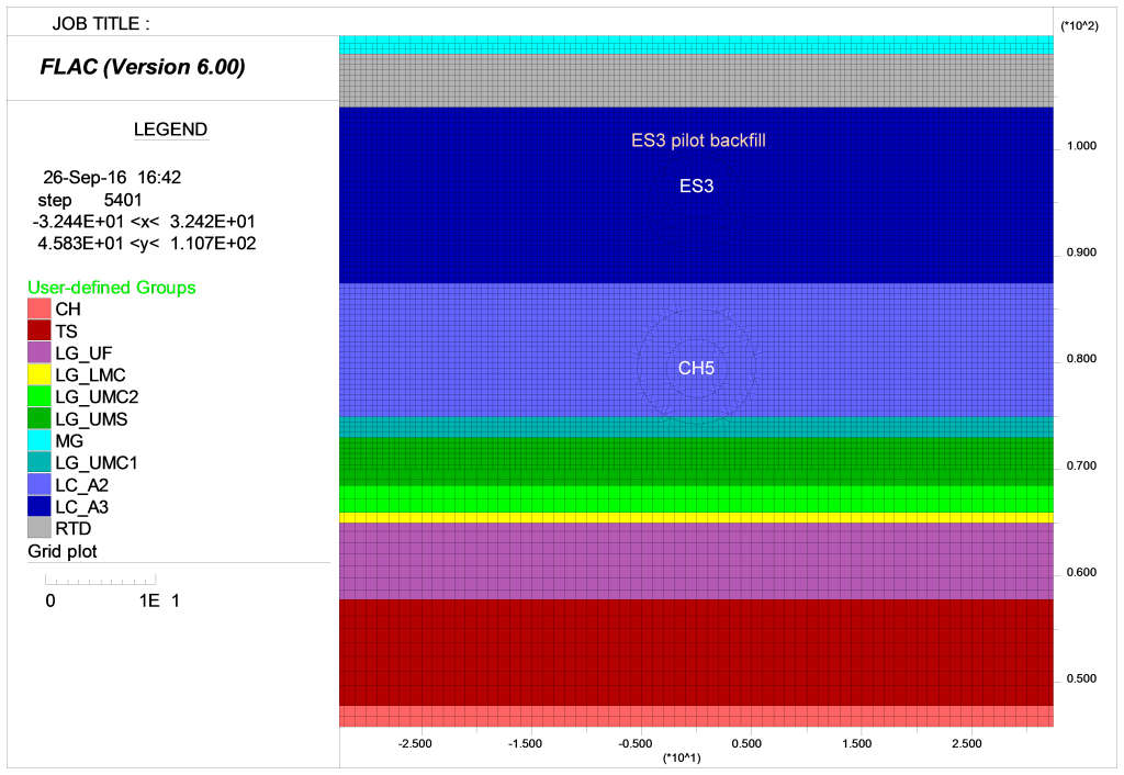
Figure 1: An example of numerical analysis mesh geometry before tunnel excavation
The sprayed concrete lining has been modelled using linear elastic beam elements attached to the periphery of the excavated grids. Full moment connections have been modelled at the nodes shared by adjacent beam elements. In order to estimate the properties of the sprayed concrete lining, a modified version of the J2 curve[1] has been used for concrete of age up to 24 hours and the Chang and Stille (1993)[2] approach has been used for concrete of age over 36 hours and up to 28 days. The concrete properties for age between 24 and 36 hours were interpolated from the above two approaches. The stiffness has been set according to the age of the lining as defined. A correction of lining stiffness (E2D) has been used in FLAC 2D analysis In order to account for the plane-strain condition.
Equation 1

Where E is the stiffness reading from J2 curve[1] and Chang and Stille (1993)[2], and ν is the poisson’s ratio taken as 0.2. An example of the sprayed concrete lining properties used in the design are summarised in Table 2.
Table 2: Example of sprayed concrete lining properties
Tunnel Type Grade of concrete
at 28 daysGrade of concrete
at 32 daysThickness ST and LT Stiffness Moment of inertia Density (mm) (GPa) (m4/m) (kN/m3) LIS-ES3 SFRC C28/34 C32/40 300 17.11 (17.67*) 0.00225 25 *17.11 is for short term stage after 28 days, while 17.67 is for long term stage after 90 days.
1.1 Age of sprayed concrete lining
The time dependent concrete stiffness has been taken into account for the tunnel lining based on the advance rates of excavation. The age of concrete for each stage has been calculated based on the previous experience in tunnel excavation and the maximum advance rate specified on the drawings provided by the tunnel excavation contractors. The SCL lining structural capacity considers not only the age of the concrete but also the beneficial effects of steel fibres contribution where applicable on the sprayed concrete tensile strength. The strength capacity of plain concrete which is less than 28 days aged has also been estimated from the reading of J2 curve[1] and Chang and Stille (1993)[2] corresponding to the associated ages.
1.2 Geological stratigraphy and geotechnical ground conditions
In Crossrail project the geological stratigraphy taken from the ground surface downward are generally started from Made Ground (MG), River Terrace Deposits (RTD), Upper London Clay Unit A3 (LC-A3), Lower London Clay Unit A2 (LC-A2), Lambeth Group – Clay above MLGH (LG-UMC), Lambeth Group – Sand above MLGH (LG-UMS), Lambeth Group – Clay below MLGH (LG-LMB), Lambeth Group – Upnor Formation (LG-UF), Thanet Sand (TS), and finished in Chalk (CH), also shown in Figure 1. Where Upper London Clay Unit A3 (LC-A3), Lower London Clay Unit A2 (LC-A2), Lambeth Group – Clay above MLGH (LG-UMC), and Lambeth Group – Clay below MLGH (LG-LMB) are clayey materials which have significantly low permeability and undrained strength and condition need to be considered in the short term stage. In the long term as the groundwater transports and groundwater pressure starts to apply on the SCL linings these layers are converted to the drained strength and condition. Not every layer has solid evidence of presence and depends on the sedimentary locations. Most SCL tunnels in Farringdon, Liverpool Street, and Whitechapel stations are excavated within Upper London Clay Unit A3 (LC-A3), Lower London Clay Unit A2 (LC-A2), and Lambeth Group – Clay above MLGH (LG-UMC) layers. Some of them have encountered localised sand channels and/or Lambeth Group – Sand above MLGH (LG-UMS) layer where a groundwater depressurisation treatment was needed to be arranged to reduce the impacts from the excess groundwater pressures.
The ground levels are varied from station to station and in Liverpool Street station 114mATD is used for most tunnels’ assessments. The geotechnical parameters and strata levels used in the Liverpool Street station were adopted from the ‘C121 Stage E – Liverpool Street Station – FLAC Parameters’ and similar procedures have used for other stations respectively. These geotechnical properties were determined from the ground investigations and laboratory testing results which an example is summarised in Table 3.
To account for the soils’ stiffness behaviour which is strain dependent, especially in the initial small strain region, a non-linear strain dependent Jardine[3] or Jardine A*[4] stiffness model has been used for soils except for the Made Ground (MG) and Chalk (CH), where the linear elastic perfectly plastic stiffness model has been used. The Jardine[3] non-linear soil stiffness model has the original equation as below:
Equation 2
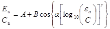
Where Eu is the undrained stiffness of the soil, Cu is the undrained strength, εa is the current strain state, and A, B, C, α and γ are the empirical constants which can be quickly determined from soil mechanics testing data. The Jardine A*[4] stiffness model is a modification of the Jardine[3] non-linear soil stiffness model in terms of initial soil stiffness condition. An example of Jardine and Jardine A* parameters are listed in Table 4.
Table 3: Geological stratigraphy and geotechnical ground parameters
Soil stratum Bottom level Unit Weight Cohesion Friction Poisson’s Ratio Porosity Dilation K0 Undrained Shear Strength Wet Dry – – – – – – – g g’ c’ m n r f’ Cu mATD kN/m3 kN/m3 kN/m2 Deg – – Deg – – Made Ground 109 20.0 16.5 0 25 – 0.35 0 0.5 – River Terrace
Deposits
104 20.0 17.0 0 38 0.3 0.30 6 0.5 – London Clay [A3] 87.5 20.0 15.5 10 22 0.1 0.45 0 1.2 70+11z* (above 98m)
120+5z*
(below 98m)
London Clay [A2] 75.0 20.0 15.5 15 26 0.1 0.45 0 1.2 110+7z* Upper Lambeth Group – Clay1 73.0 21.0 16.5 25 27 0.1 0.45 0 1.2 110+7z* Upper Lambeth Group – Sand 68.5 21.0 17.5 0 37 0.2 0.35 8 1.2 – Upper Lambeth Group – Clay2 66 21.0 16.5 25 27 0.1 0.45 0 1.2 110+7z* Lower Lambeth Group – Clay 65 21.0 16.5 25 27 0.1 0.45 0 1.0 45+7.5z** Lambeth Group Upnor Formation 57.8 21.0 17.5 0 37 0.2 0.35 8 1.0 – Thanet Sand 47.8 21.0 17.5 0 39 0.2 0.35 10 1.0 – Chalk 30 20.0 16.5 30 30 0.25 0.35 0 1.0 – z* is depth below surface of London Clay
z** is depth below 110mATD
Table 4: Jardine and Jardine A* parameters used in Liverpool Street Station
Soil Type (Abbr.) A*hh0 A B C a g Gmin
(kPa)
esmin esmax (MPa) London Clay (A3) (LC-A3) 5+0.04z* 0.42 0.28 5.0E-05 1.76 0.79 4000 5.0E-05 2.0E-03 London Clay (A2) (LC-A2) 3.2+0.14z* 0.42 0.28 5.0E-05 1.76 0.79 4000 5.0E-05 2.0E-03 Upper Lambeth Group Sand (LC-UMS) – 2185 2066 7.0E-06 1.37 0.685 10000 7.0E-06 1.95E-03 Upper Lambeth Group Clay (LG-UMC) 8.5 0.42 0.28 5.0E-05 1.76 0.79 7000 5.0E-05 2.0E-03 Lower Lambeth Group Clay (LG-LMC) – 1500 1389 2.3E-05 1.61 0.69 7000 2.3E-05 2.23E-03 Lambeth Group Upnor Formation (LG-UF) – 2404 2320 7E-06 1.38 0.7 10000 7.0E-06 1.95E-03 Thanet Sand (TS) – 2938 2837 7E-06 1.35 0.735 10000 7.0E-06 1.95E-03 z* is depth below London Clay surface
An example of groundwater pressure profile is also listed in Figure 2, where the dotted line represents the current groundwater pressure profile from geotechnical ground investigations, and the solid bold line and dashed line are an expectation for Crossrail’s design life (120 years) in the future.
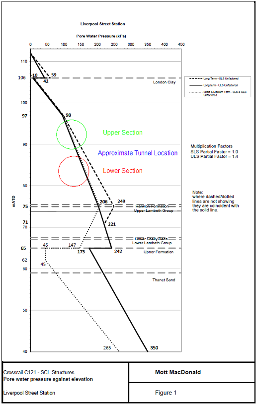
Figure 2: An example of groundwater pressure profile used in Liverpool Street station
1.1 Construction sequences
The numerical analysis follows the construction programme and the excavation peak advance rate. This rate is reflected not only on the sprayed concrete stiffness (used in the analysis) but also on the strength (applied in the design capacity checks). The pilot tunnel lining when installation is calculated as 4.5 hours aged in most cases as the average of the first advance (6 hours) and the second advance (3 hours) is taken for consideration. It is then developed to certain aged when the excavation of permanent tunnel is commenced, based on the assumption of average advance rate and the total numbers of advances required plus the preparation time if known. The backfills of temporary tunnel with concrete have been considered as a separate concrete block as it ages and carries partial of the ground loading before the permanent tunnel excavation and permanent lining is in place. The age of the top heading lining of the permanent tunnel when installation is calculated based on the separate top heading advance rate if a top heading-invert two stage construction method is adopted. It is then developed to certain aged when temporary invert is removed and the construction of the final invert enlargement if the temporary invert exists. The age of the final invert lining is also calculated from a separate advance rate when installation. All lining properties are set to 28 days aged for short term analysis and 90 days aged for long term analysis.
2. Tunnel built on the top of backfill
This design normally encounters when an earlier access tunnel was built in need beneath the permanent tunnels, to transport the equipments or the tunnelling staffs. For example at escalator tunnel ES1 at Farringdon station, escalator tunnels ES2 and ES3 and northern line link tunnel AP6 at Liverpool Street station.
2.1 Backfilled with foam concrete
Foam concrete has the benefit of light-weighted, however it will be degraded with time and both the degraded stiffness and strength are difficult to predict. Table 5 compares the key properties of the different concretes being used and the surrounding London Clay- A2 soils in the analysis.
Table 5: The comparison of different concrete properties being used in analysis
SFRC Foam concrete Foam concrete degraded London Clay A2 Density (kN/m3) 25 16 21 (saturated) 20 (saturated) Stiffness (GPa) 16.96 5 0.2 Varies with depths and strain levels (0.02~0.05) Poisson’s ratio 0.2 0.2 0.2 – Strength (MPa) 32 20 – Drained cohesion: 0.015 Friction (degree) – – 35 26 Short term behaviour
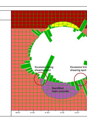
In the short term the backfilled foam concrete has significant strength and stiffness before degradation, and is considered as impermeable where the groundwater cannot flow through it. The strength and stiffness difference between the SFRC and foam concrete at the underneath backfilled temporary tunnel (the temporary tunnel was also built with SFRC lining first and then backfilled with foam concrete) will however create excessive shearing spots on the permanent tunnel invert lining above it due to differential settlements. The excessive shearing spots induced by the broken SFRC lining of the temporary tunnel below protruding the upper tunnel invert lining and creating excess bending moments and localised shear stress on the above lining. Figure 3 shows an original analysis for Liverpool Street station escalator ES2 tunnel primary lining before taking remediation actions. The green bars show the shear forces on tunnel linings. The excessive shearing spots are highlighted by red circles where present the influence by the bottom backfilled temporary tunnel.
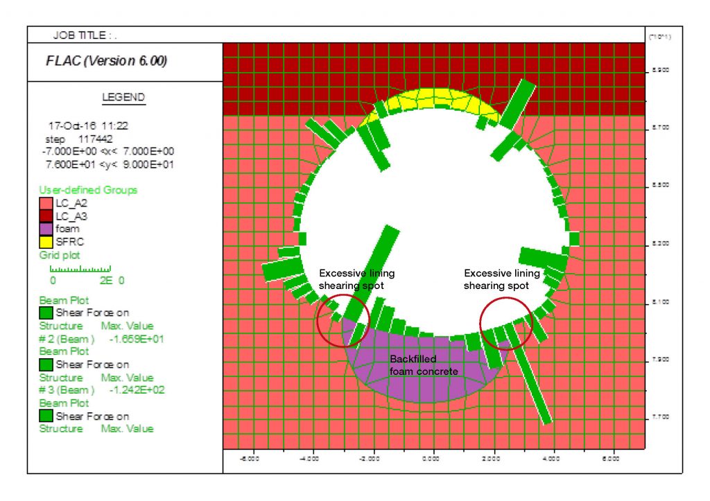
Figure 3: Foam concrete backfills induced excessive shearing spots at the invert lining
Long term behaviour
The long term strength and stiffness difference between the backfilled foam concrete and the adjacent broken remaining SFRC lining is even more prominent because of the degradation of the backfilled foam concrete. The stiffness degradation of foam concrete is from 5 GPa originally down grade to 0.2 GPa in the long term case. The groundwater is assumed to be able to flow through the degraded foam concrete and groundwater pressure applies on the permanent tunnel linings. The surrounding London Clay in general has less strength from undrained to drained condition and due to the compressibility of the clay the permanent tunnel linings have carried bigger bending moment and shear force. The recovery of the groundwater pressure has promoted the floating up of the tunnels, and the permanent tunnel invert lining itself has heaved up a bit in the centre towards inward of the tunnel due to the presence of groundwater pressure. Both sides of the invert lining are therefore bending outward to balance the forces as shown in Figure 4. In Liverpool Street station escalator ES2 tunnel primary lining, due to the limitation of movements at the crown by another SFRC backfill, the bending moment does not develop as much at the inward face of the top heading lining underneath the crown backfill, however the moment does build up at the edges where the crown backfill ends to the top heading lining. The backfilled concrete on the crown case will be discussed later in Section 3 of this article.
The axial force in the long term shows reduction in those excessive shearing spots where the SFRC lining of bottom backfilled temporary tunnel protrudes the above permanent invert lining. The axial force distribution for the rest part of the lining does not have significant impacts due to the backfilled temporary tunnel, and similar results have also been observed in shear force distribution on the permanent tunnel linings.
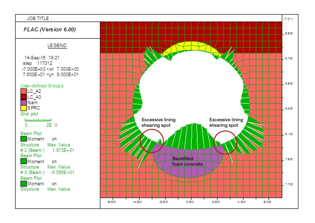
Figure 4: Bending moment distribution after foam concrete degraded in long term
Remediation methodology
In order to remove the excessive shearing spots on the permanent invert lining caused by the bottom backfilled temporary tunnel, due to the temporary tunnel SFRC lining is much stiffer than the degraded foam concrete, a minimum thickness of foam concrete and temporary tunnel SFRC lining are required to be removed and replaced with the same SFRC materials used for the above permanent tunnel linings. This replacement should provide a uniform, sturdy, and flat foundation to support above permanent tunnel linings and act as a partition layer to preclude the influence from the degradation of bottom backfilled temporary tunnel.
2.2 Backfilled with plain concrete
Similar to the backfills of foam concrete, however the plain concrete has closer properties to the above permanent tunnel linings and normally would not be expected to have significant degradation in terms of concrete properties, especially the strength and stiffness in the long term. This type of temporary tunnel backfills provide better consistency to the above permanent tunnel linings however the gap of the stiffness difference between the backfilled plain concrete and the surrounding soils is inevitably increased. The position of the permanent tunnel invert lining and the backfilled concrete becomes prominent to the impacts of the invert lining capacities. To avoid the sharp transition between the backfilled tunnel and the adjacent soils, the selection of the permanent tunnel to be excavated closer to the backfilled temporary tunnel axis level may be preferred, to have a sufficient contact area between the permanent tunnel invert lining and the backfilled concrete beneath.
Short term behaviour
The analysis found that in the short term undrained condition as an example of AP6 tunnel at Liverpool Street station in Figure 5, the bottom plain concrete backfilled temporary tunnel helps to reduce the majority of the bending moments acted on the permanent invert lining compares to the foam concrete backfills, as well as reducing the shear forces induced at the edges of the backfilled concrete. However the axial force which helps the invert lining capacity also drops at this area, especially closer to the edges of the backfilled concrete and the surrounding soils. If counting the backfilled concrete and the permanent tunnel SFRC lining as a whole integrity lining this may not be a significant problem because the lack of axial force will induce cracks at the inner face of the permanent lining and the thickness of the backfilled concrete plus SFRC lining has more than the capacities required.
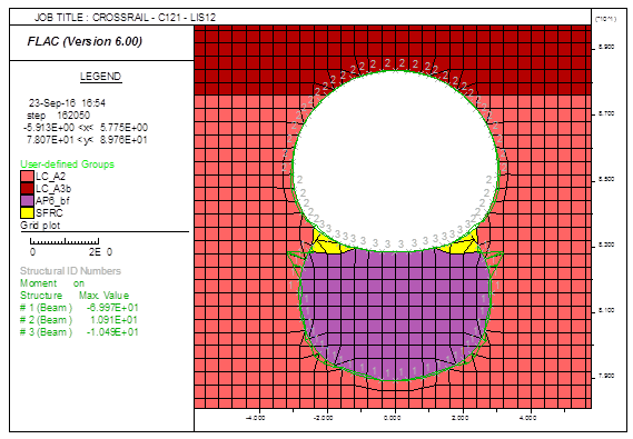
Figure 5: Bending moment distribution at short term stage of a tunnel built on the top of plain concrete backfills
Long term behaviour
In the long term drained condition as an example of the same AP6 tunnel in Figure 6, because of the assumption that the groundwater pressure will apply on the permanent invert lining due to lack of water-proof system in the backfilled temporary tunnel, the bending moment grows most on the permanent invert lining at the backfilled concrete edges, however the axial force which helps the concrete lining capacities also increases due to the presence of groundwater pressure which applies on the permanent SFRC linings. The design lining capacities need to consider the combination effects of bending moment, axial force, and shear force specifically for every location of the permanent tunnel linings. Note that the maximum bending moment at the permanent linings does not necessary locate at the same location where has the lowest or biggest axial force/stress and shear force/stress.
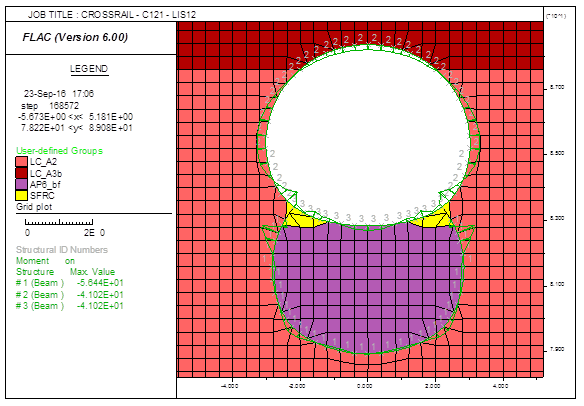
Figure 6: Bending moment distribution at long term stage of a tunnel built on the top of plain concrete backfills
3. Tunnel built on the base of backfill
This situation normally encounters when the pilot tunnel’s axis is much higher than the enlarged permanent tunnel axis and it intrudes the top heading of the permanent tunnel. Plain concrete or SFRC is used to fill the voids left between the pilot tunnel and the top heading lining of the permanent tunnel because of the difficulty to stabilise the foam concrete on the crown. For example at escalator tunnel ES1 at Whitechapel station, and escalator tunnels ES2 and ES3 at Liverpool Street station.
Short term behaviour
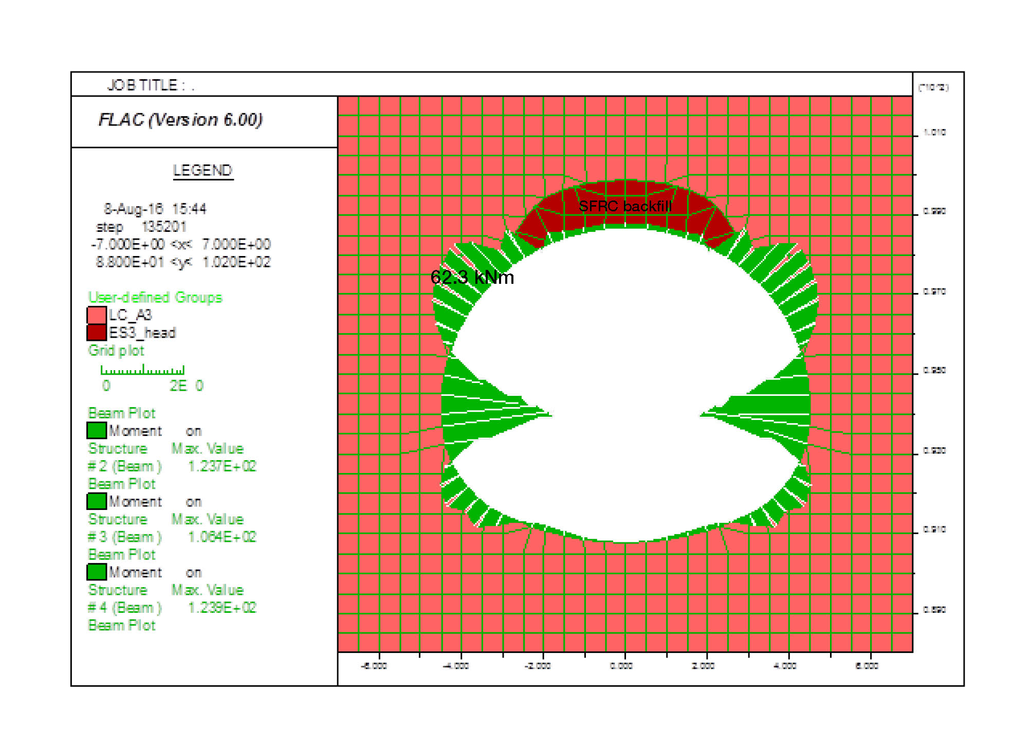
In the short term as an example of ES3 tunnel original design in Liverpool Street station in Figure 7, the groundwater pressure cannot access to the crown backfilled concrete and neither does the rest part of the permanent linings if the tunnel is fully located in London clay layers. The loading difference induced by the backfills on the permanent tunnel lining at the crown is insignificant in most cases because of the density of both the concrete and the surrounding soils are quite similar to each other and assuming that the crown backfilled concrete is not very thick.
The bending moments of the permanent tunnel linings at bench and at invert show mostly insignificant difference to the tunnel linings without adjacent concrete backfills, however the shoulders where nearby the backfilled concrete edges have significant bending moment increase, and nearby the same spots the shear force also increases. The axial force under the backfilled concrete is much smaller compared to other parts of the tunnel linings, especially close to the edges where the backfilled concrete ends. These results are explained by the sharp decrease in stiffness and strength from backfilled concrete to London Clay, where the edges of the backfilled concrete transfer localised pressures to the permanent tunnel linings and release nearby axial force while increasing the shear force and nearby bending moments. The tunnel deflection shape is believed to be influenced by the crown concrete backfills as shown in Figure 8. Although the shape of the permanent tunnel linings itself does not look vertically ellipse (egg shape), the overall tunnel deflection shape behaves so. The excavation of the pilot temporary tunnel has contributed to the final deflection shape of the permanent tunnel linings, no matter if it has been backfilled before the permanent tunnel excavation, if no debonding layer is installed in between.
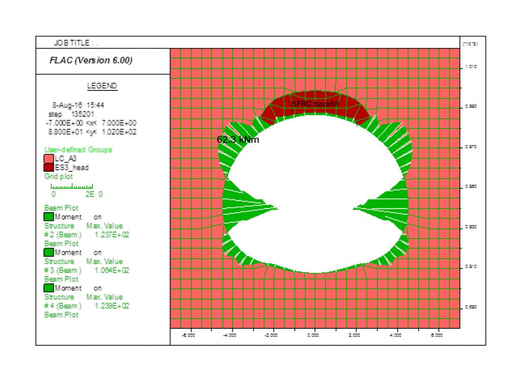
Figure 7: Bending moment distribution at short term stage of a tunnel built beneath SFRC backfills
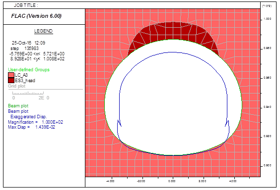
Figure 8: The crown concrete backfills have affected the permanent tunnel lining deflection as shown in blue line (exaggerated) where flatter deflection shape was expected if without the backfills
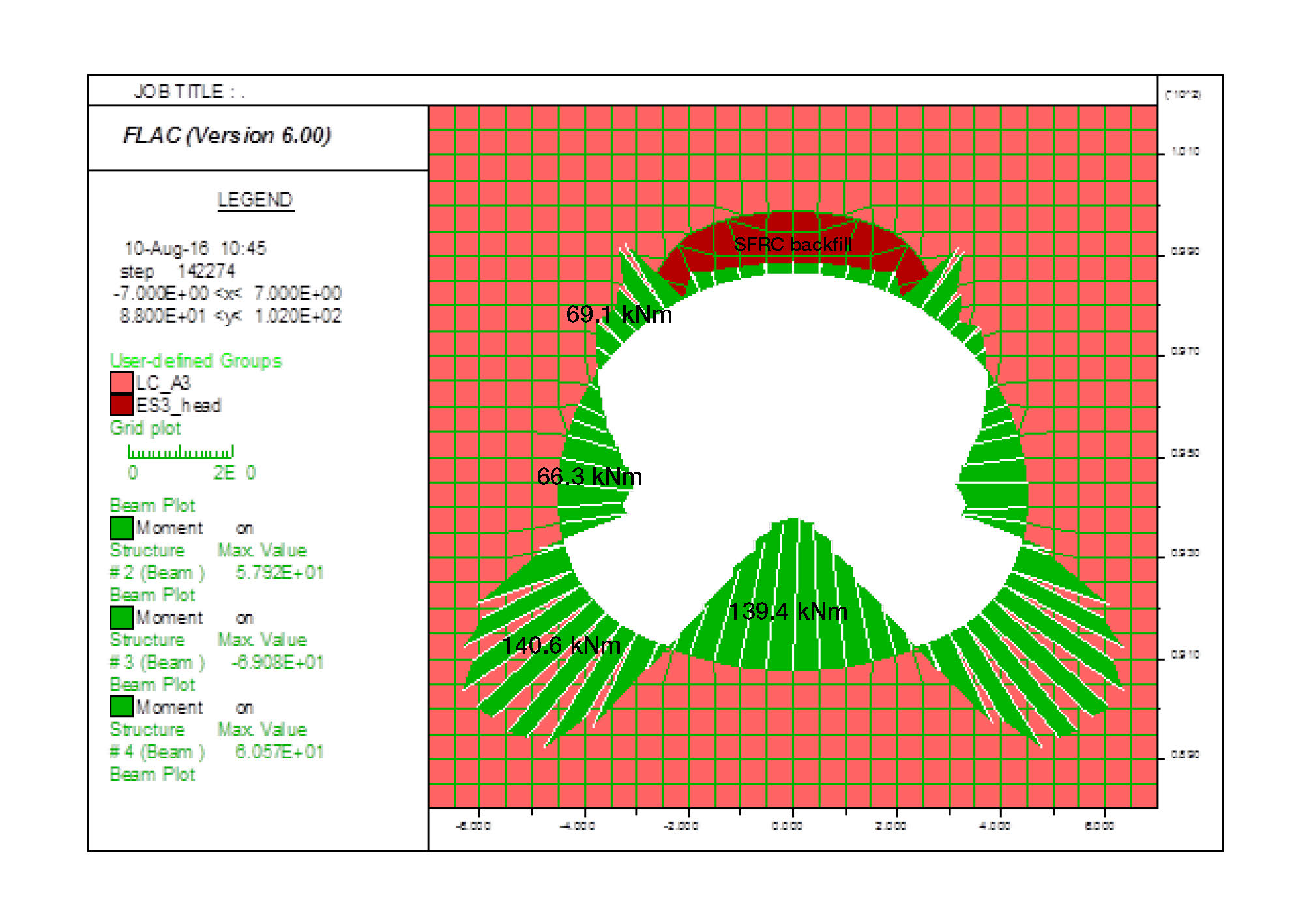
Long term behaviour
In the long term the groundwater pressure is assumed to apply on the tunnel linings. Figure 9 presents an example of the same ES3 tunnel original design in Liverpool Street station. The backfilled concrete on the crown limits the deflection of the permanent tunnel lining at top heading towards upward and therefore generates more beading moments on the shoulders. The centre of the bottom invert lining generally heaves up due to the effects of groundwater pressure applying on the permanent tunnel linings. To counterbalance this, both sides of the lower benches have developed bending moments outward at the outer-face. The bending moments developed much larger at lower benches than the rest parts of the permanent linings is suspected that due to the effect of the limitation of the permanent tunnel moving upward after groundwater pressures applied. The axial force in the long term generally increases due to the groundwater pressures apply on the permanent tunnel linings. Similar to the short term case, the top heading lining of the permanent tunnel close to the edges of the crown concrete backfills has significant less axial force due to the stiffness and strength difference between the surrounding soils and the concrete backfills. The shear force also increases at nearby spots on the top heading lining in the long term and additional shear force has induced at the invert lining due to the heave of the invert by groundwater pressures.

Figure 9: Bending moment distribution at long term stage of a tunnel built beneath SFRC backfills
4. Debonding layer and reinforcement
A debonding layer may be recommended to install between the backfilled temporary tunnel and the permanent tunnel’s outer-face of linings, if the backfilled concrete is known to have complicate effects to the permanent linings. This is normally to associate with an unusual lining shape which causes structural unstable of the linings, or the backfilled material itself is unstable and degraded with time. In either case a sufficient thickness of SFRC lining is still required after the debonding layer, which helps the two concrete materials behave separately and work in its own capacities.
Reinforcements are normally needed at the edges above or beneath of different backfill materials, either in primary or secondary lining or both if primary lining is considered as a permanent structure to carry the loads in the long term. This is to prevent the long term damage to the linings caused by the degradation of the backfilled concrete and the consolidation of surrounding soils. Additional reinforcements are required at the locations where bending moments are outside of the capacity. These arrangements are depended on the construction sequence, tunnel shape and location, and surrounding geological and groundwater conditions. Individual study may be required for specific tunnel reinforcements design.
5. Conclusions
The impacts of SCL primary lining interactions with concrete backfilled temporary tunnels have been studied by using numerical analysis FLAC 2D finite difference program. The results prove that the stiffness difference between the backfilled concrete and nearby soils could potentially affect the permanent SCL primary lining by generating excessive shearing spots on the tunnel lining at the edges of the backfills, especially in long term condition with groundwater pressure applies on the linings and backfilled concrete is partially degraded. This excessive shearing spots on the lining will induce excessive bending moment and shear force along the lining and may exceed the SCL lining strength capacities. The excessive shearing spots on the lining will be exaggerated when backfilled foam concrete in the middle degraded much more than the enclosure temporary tunnel SFRC linings.
A remediation method is usually recommended if the backfilled concrete is thick enough to have significant impacts to the outside shape of the permanent tunnel, normally happened below the invert of the permanent tunnel linings. This remediation requires the cutting back of the concrete backfills and temporary tunnel SFRC linings to an appropriate thickness, and replaced by a uniform material which will be used for permanent tunnel SFRC linings, to provide a rather stable and flat foundation for permanent tunnel construction.
From the 2D study it seems that the backfilled temporary tunnels on the crown is less detrimental to the permanent tunnel linings beneath it. This probably is on the assumption that the backfilled concrete has similar materials’ density to the surrounding soils hence the permanent tunnel linings react indifference to the ground or to the backfilled concrete loads. Similar results may be expected for extension longitudinally, as long as the backfilled concrete does not have sharp end finishes. However the backfilled concrete does affect the predictions of tunnel lining deflection shape if no debonding layer between the backfilled temporary tunnel and the permanent tunnel is used. The area of the backfilled concrete has contributed to the final shape of deflection in addition to the permanent tunnel linings.
For the backfilled temporary tunnels beneath the invert of the permanent tunnel linings a debonding layer and/or reinforcements may be considered, to alleviate the overstressed spots on the permanent tunnel linings or to enhance the SCL lining capacities in terms of bending moment and shear force. The locations of overstressed bending moment may be shifted to the shoulders or to the lower side benches if both crown and invert have concrete backfilled temporary tunnels. It is important to consider each case individually for reinforcement designs, especially to account for geological and groundwater conditions, geotechnical parameters, permanent tunnel shape and location, and backfilled concrete materials and location.
Acknowledgements
The author acknowledges the advice given by Mr Chris Pound, who provided magnificent opinions on the numerical modelling as well as the SCL behaviours in soil-structure interaction. The author also likes to express the gratefulness for many useful discussions among Crossrail C121 SCL design team for concrete structure properties.
References
[1] British Standard (2006) Sprayed concrete – Part 1: Definitions, specifications and conformity (BS EN 14487-1:2005) – BSI Electronic Catalogue
[2] Chang, Y and Stille H (1993). Influence of early-age properties of shotcrete on tunnel construction sequences. Shotcrete for Underground Support VI – American Society of Civil Engineers
[3] Jardine, R.J., Potts, D.M., Fourie, A.B. and Burland, J.B. (1986). Studies of the influence of non-linear stress-strain characteristics in soil-structure interaction. Geotechnique 36, No. 3, 377-396.
[4] Eadington, J. and O’Brien, A.S. (2011). Stiffness parameters for a deep tunnel – developing a robust parameter selection framework. Proceedings of the 15th European Conference on Soil Mechanics and Geotechnical Engineering, 531-536.
-
Authors

Dr Chin-Kang Shen MSc DIC PhD CEng MICE - Mott MacDonald
Dr Shen gained extensive geotechnical and tunnel experience prior to joining Crossrail C121 as the lead design engineer of sprayed concrete primary lining designs. He has been awarded both MSc and PhD degrees of Civil Engineering from Imperial College London, and is a chartered engineer of ICE and a specialist of RoGEP. He worked in Los Angeles before moving to London where he made significant contributions to earthquake dynamic designs. His expertise and interests are applying numerical analysis to solve practical engineering challenges, fluent in finite element, finite difference, and discrete element methods and he has published several papers throughout his PhD works.