Site installation practices for mechanical systems in Crossrail
Document
type: Technical Paper
Author:
Wing Fung PhD MSc BSc(Eng) CEng MCIBSE, ICE Publishing
-
Read the full document
Introduction
A good level of consistency in mechanical system design and construction is achieved at Crossrail stations, shafts and portals. This has been possible through implementation of a set of generic material and workmanship specifications, technical assurance procedures and guidance notes. Contractors at different worksites might take different approaches on design or adopt different sets of construction details on the installation works. This will result in minor variations in deliverables from one worksite to another, although they all satisfy the performance criteria stipulated in the works information. These diversities are deemed acceptable in consideration to the nature of work and impact on service.
The collection of site photographs presented in this paper will help illustrate installation work practices adopted at various worksites with a view to highlight their commonalities and differences. The photos are snap shots of the work in progress as of the time of publication of the paper. Many of the photos show temporary works, protection and tools which do not form part of the finished installation. Furthermore, they are not meant to cover all aspects of installation. Some of them represent good installation practices and should be adopted in other worksites and future projects.
The purpose of this paper is to encourage quality and consistency of installation work through the application of an appropriate quantity of documentation. This could be applied to similar projects.
1.1 Air cooled chiller (1 of 3)
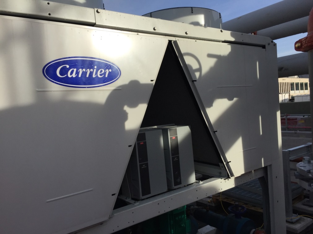
A space saving proprietary design with the variable speed drive in between the condenser coils.
Photo taken at Tottenham Court Road Station
1.2 Air cooled chiller (2 of 3)
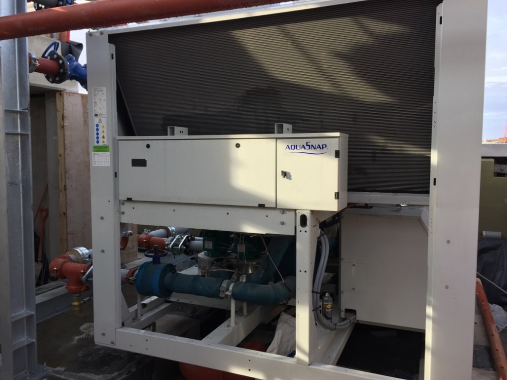
The control panel of the compressor and circulating water pumps are mounted inside the chiller unit, accessible from the side.
Photo taken at Tottenham Court Road Station
1.3 Air cooled chiller (3 of 3)
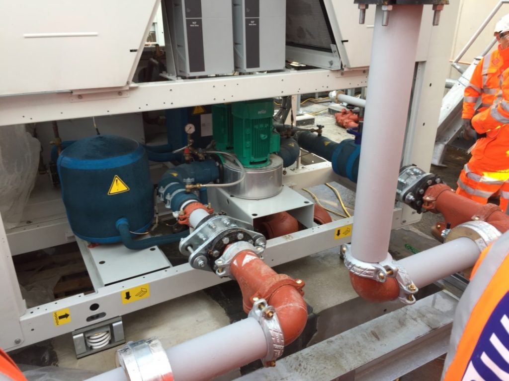
Primary chilled water pumps, evaporator and compressors (behind the pump) at the lower chassis. UV-stabilised insulation is used for chilled water/ evaporator pipes that are exposed to outdoor conditions (alternatively a UV shield is provided).
Photo taken at Tottenham Road Station
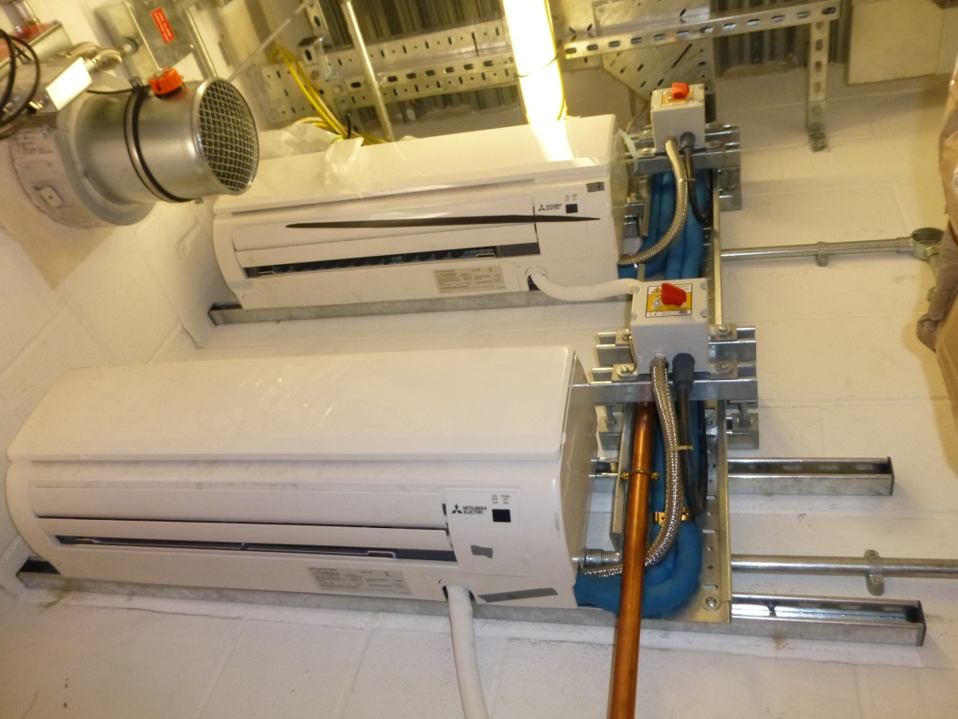
1.4 DX (indoor) units
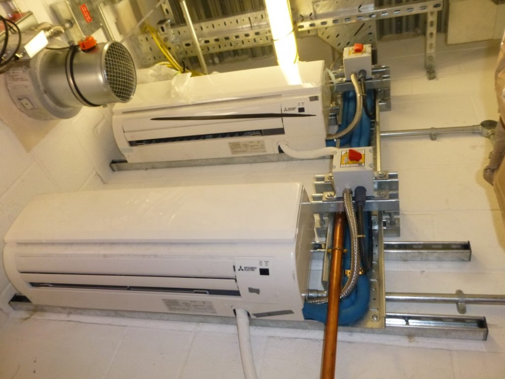
Wall mounted duty and standby indoor cooling units with a common condensate drain pipe.
Photo taken at Whitechapel Station (Temporary Ticket Hall)
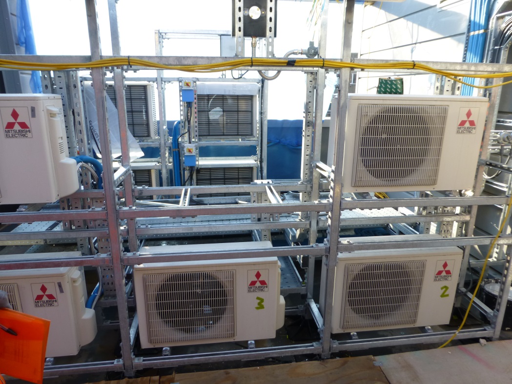
1.5 DX (Outdoor) units
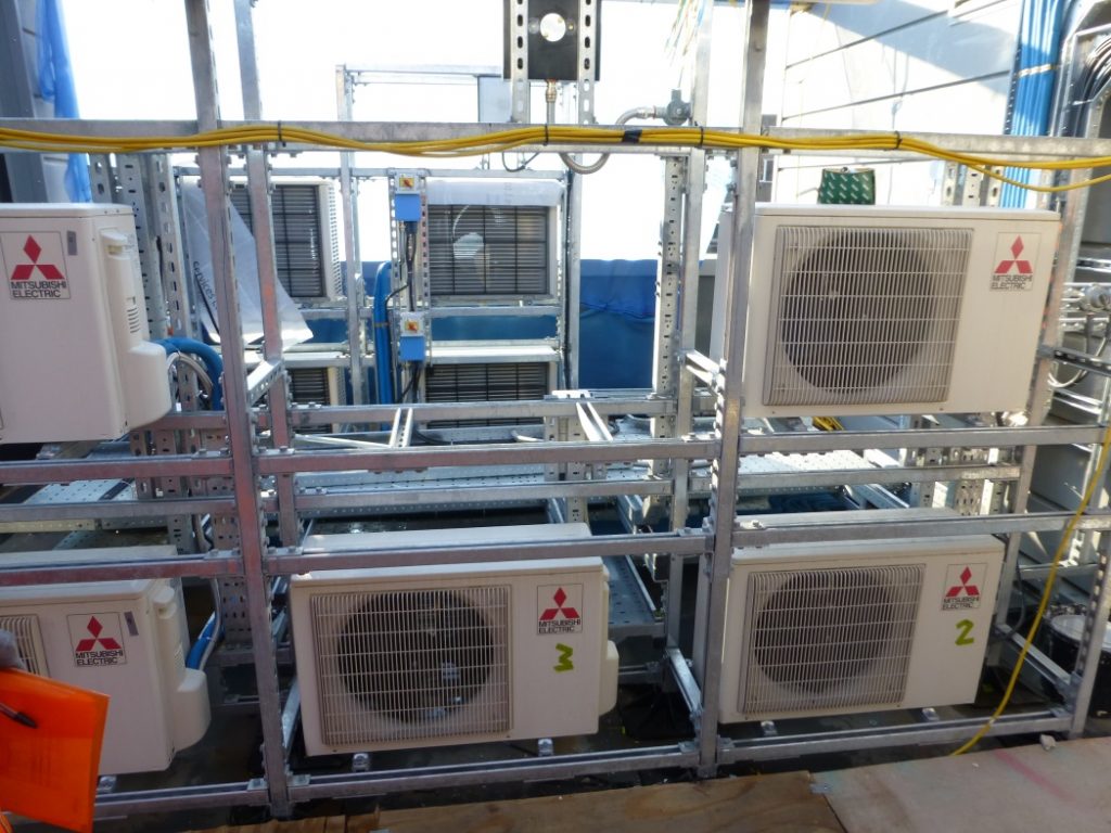
Banks of outdoor heat rejection units mounted on a steel chassis. Effectiveness of heat rejection, noise impact and access/ maintainability were some of the considerations for their location and orientation.
Photo taken at Whitechapel Station (Temporary Ticket Hall)
1.6 Air handling unit
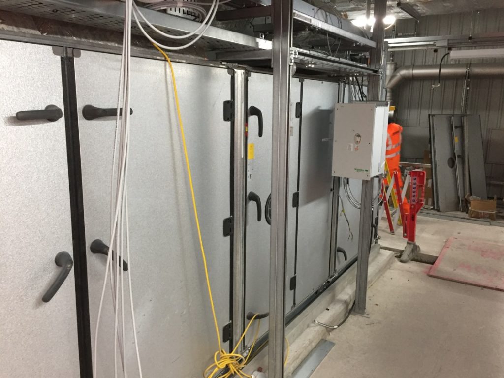
Side panels allow every section of the AHU to be fully accessible. Variable speed drive of the panel is mounted next to the fan chamber.
Photo taken at Liverpool Street Station
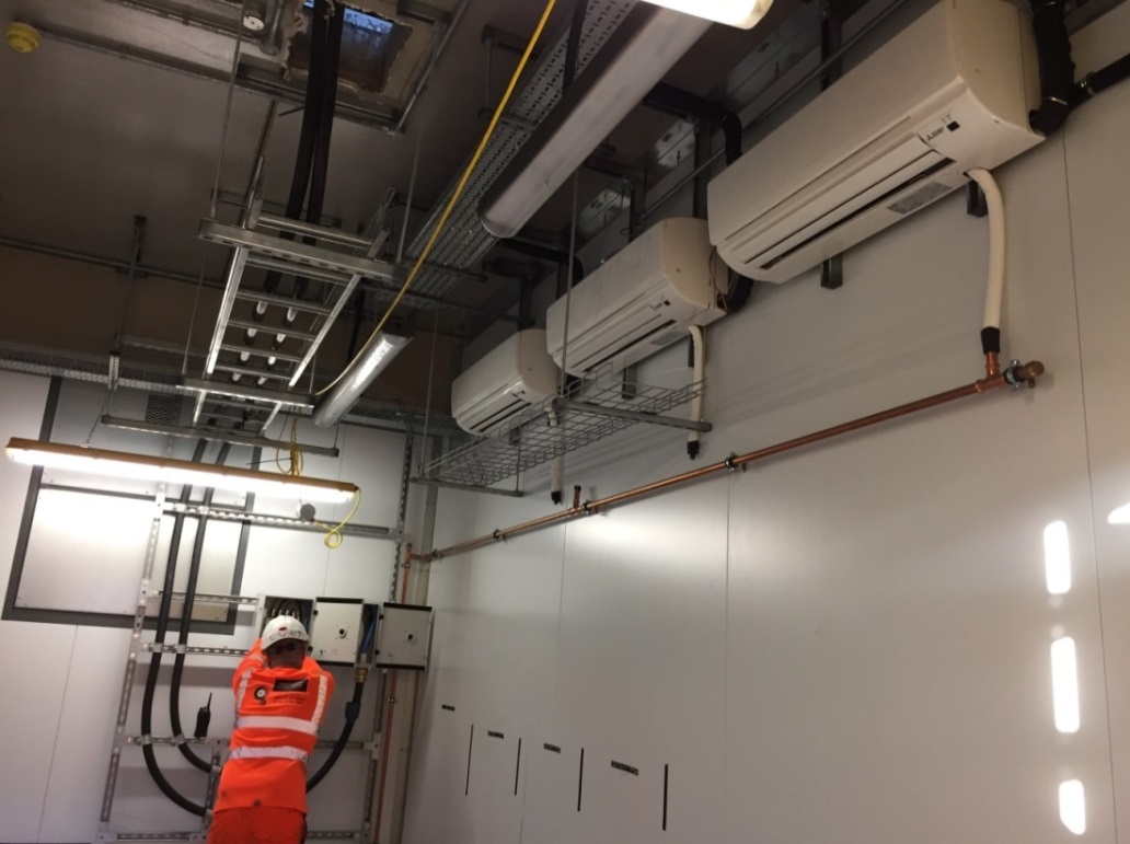
1.7 Fan Coil Units
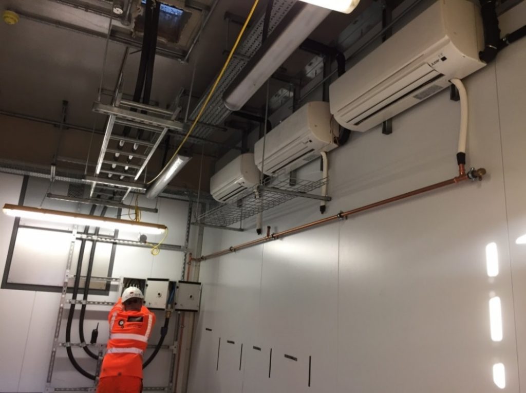
Three fan coils mounted on the side wall (N+1 configuration). Access is provided at the common copper drain pipe to clear any pipe blockage.
Photo taken at Custom House Station
1.8 Close Control Units (CCU)
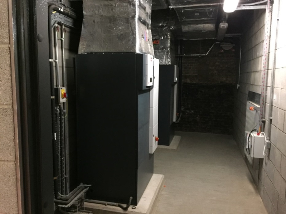
Two CCUs (sometimes referred to as Comfort Cooling Units) are installed in a dedicated plant room suppling cooling to the adjacent equipment room. The CCU is provided with in built process controller and interfaces.
Photo taken at London Bridge Station, Network Rail (London Bridge Station Improvement Project)
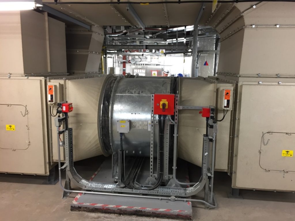
1.9 Ventilation Fans (1 of 2)
Duty and standby fans connected in parallel. Each fan set consists of contra-rotating two stage fans. Connection pieces are yet to be installed. The photo shows how steelwork/struts, conduit, isolators and VSDs should not obstruct duty/Standby fan removal.
Photo taken at Whitechapel Station
1.10 Ventilation Fans (2 of 2)
Electrical isolation switches are provided to the fan motor and the driving motors of the isolation dampers. In Crossrail, a motorised isolation damper is provided to one end of the fan assembly only (manual damper on the other end).
Photo taken at LUL Bond Street Station (Bond Street Station Upgrade Project)
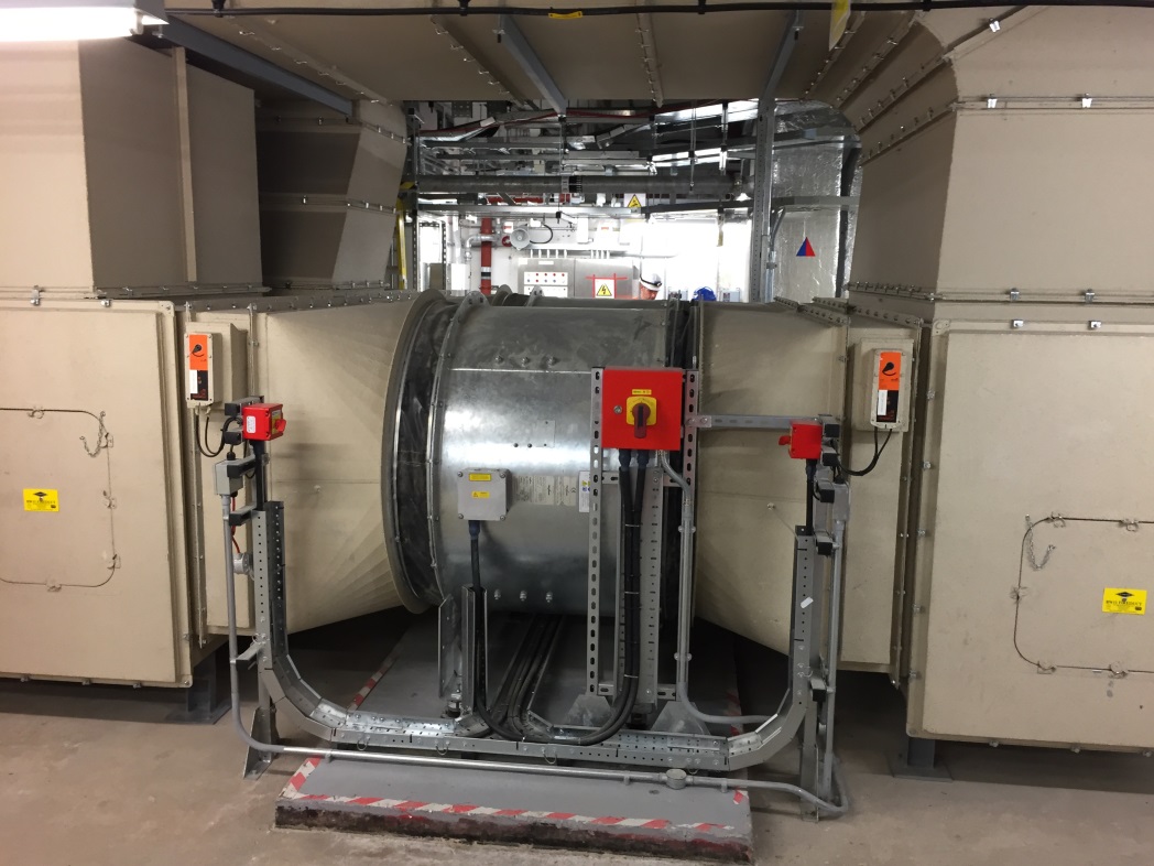
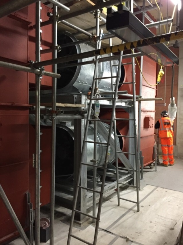
1.11 Tunnel Ventilation Fans
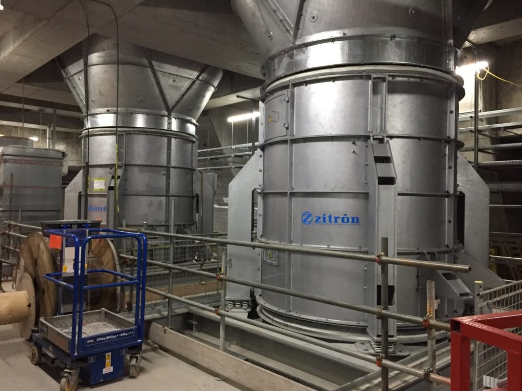
The fan support structure, maintainability and delivery of key components and mitigation of breakout noise are some of the important issues to be addressed on the installation of tunnel ventilation fans.
Photo taken at Bond Street Station
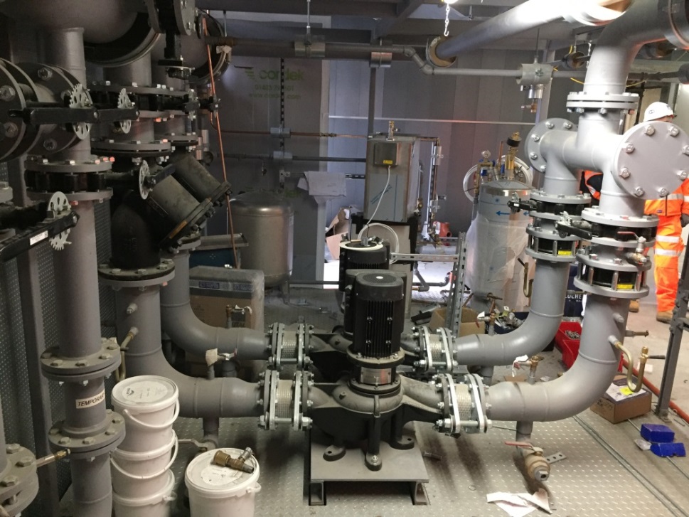
1.12 Water Circulation Pumps (1 of 2)
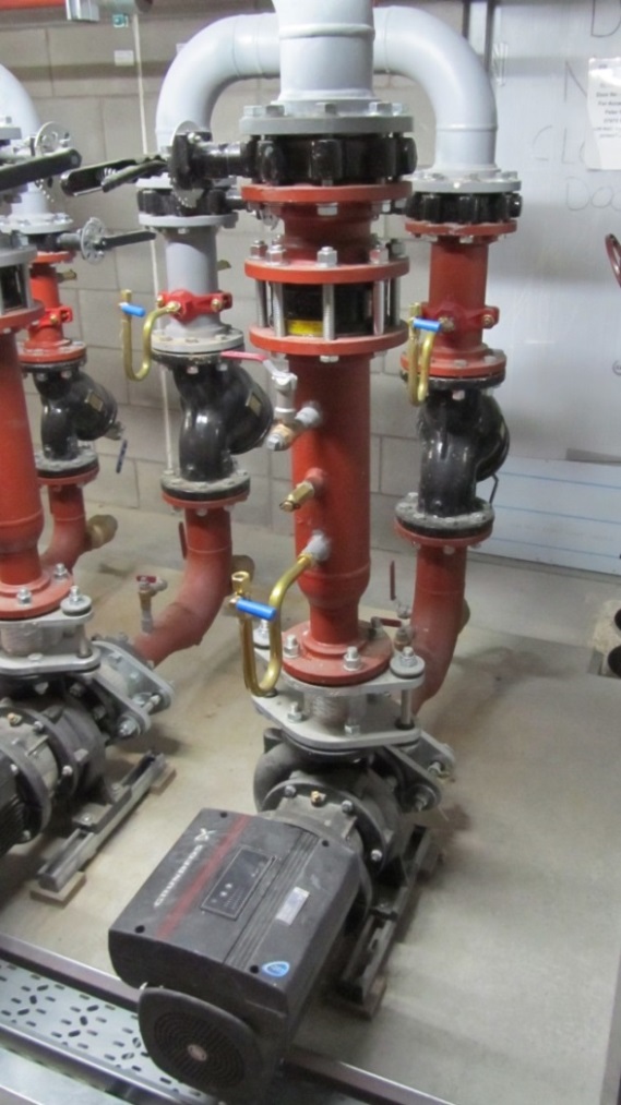
End suction pump. Variable speed drive forms an integral part of the motor assembly.
Photo taken at Liverpool Station
1.13 Water Circulation Pumps (2 of 2)
Secondary chilled water pumps and variable speed drive.
Photo taken at Bond Street Station
1.14 Side stream filter

The side stream filter maintains total iron levels of the water circuit < 1.0 mg/l, removes excess hardness by pH elevation and allows automatic backwash.
Photo taken at Tottenham Court Road Station
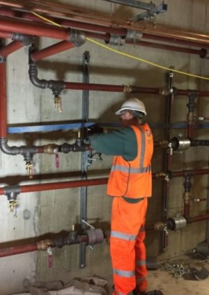
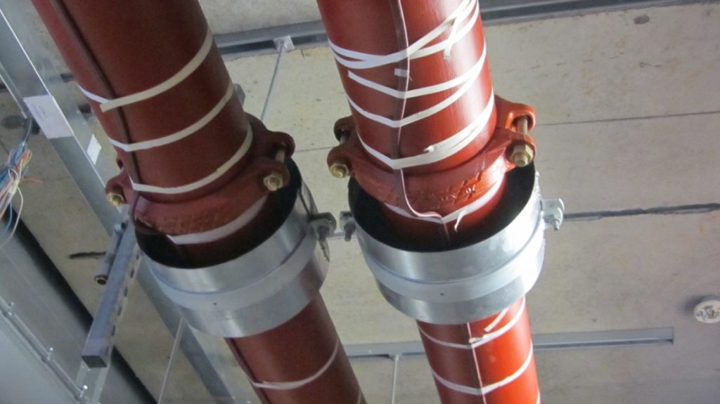
1.15 Pipe joints
Primary chilled water pipes for the cooling system. Insulation and mechanical protection are yet to be installed.
Photo taken at Farringdon Station
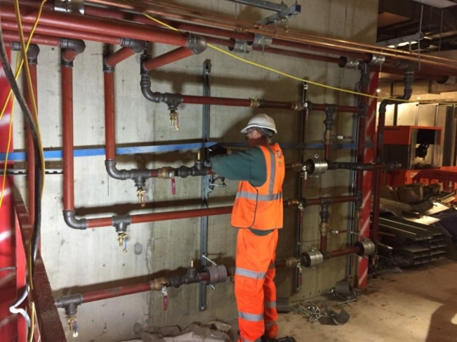
1.16 Pipework supports
Regulating valves installed for water balancing.
Photo taken at Liverpool Street Station
1.17 Expansion Joints
Flexible connector is provided at the Insulated air duct and multi-channel cable trunking at the building expansion joint.
Photo taken at Bond Street Station
1.18 Trace Heating
Trace heater is provided for water pipes exposed to outdoor condition. Thermal insulation is yet to be installed to the pipes.
Photo taken at Liverpool Station
1.19 Support for insulated water pipe
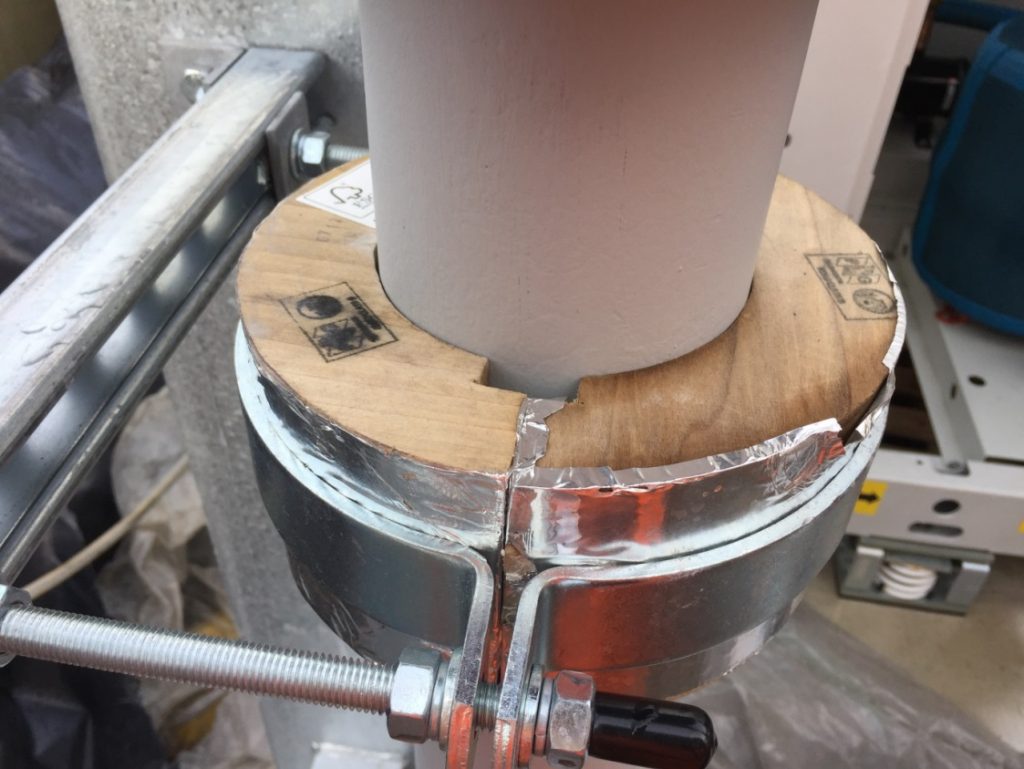
Certified wooden blocks used as a part of the pipe insulation design. Thermal insulation is yet to be installed to the pipe.
Photo taken at Tottenham Court Road Station
1.20 Supports for Air ducts
Duct routes, supports and maintenance access set out neatly.
Photo taken at Woolwich Station
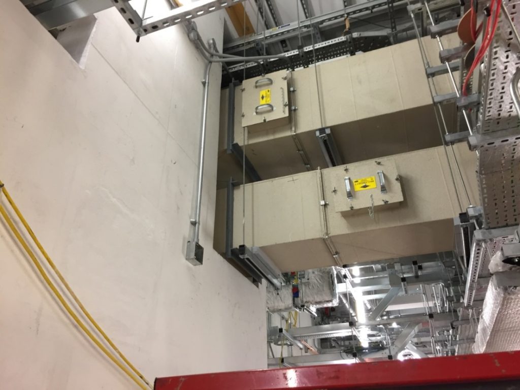
1.21 Sound Attenuators
Acoustic assessment is an important part of the design exercise to minimise environmental impact to the surroundings.
Photo taken at Woolwich Station
1.22 External Intake/ Exhaust Air Louvres
Attention was made in the design on the position and orientation of the outdoor louvres to address issues like break out noise and environmental impacts.
Photo taken at Woolwich Station
1.23 Vibration Isolator
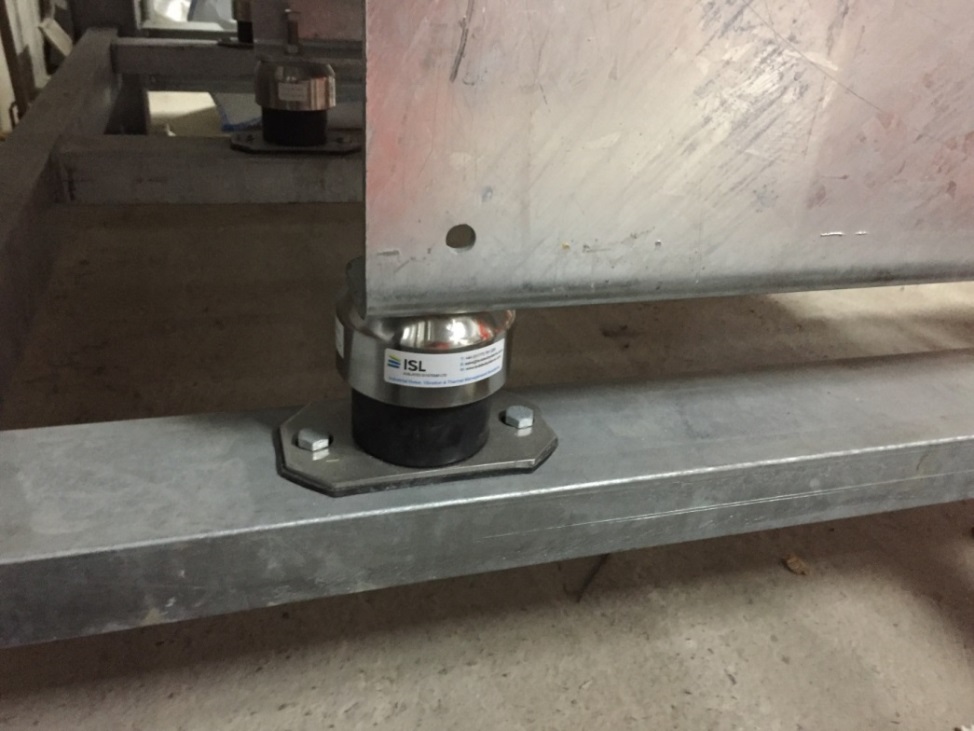
Structure borne noise and vibration are part of the MEP service design.
Photo taken at Whitechapel Station
1.24 Air Duct
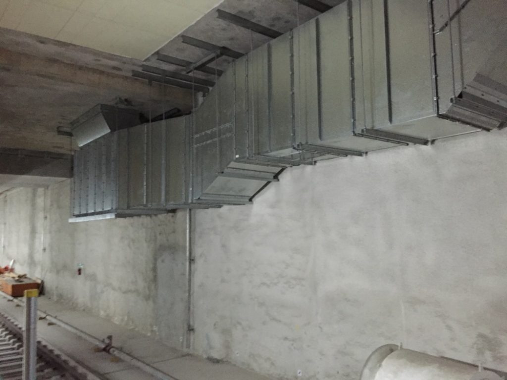
Provision for air balancing, accessibility for maintenance and duct cleaning and breakout noise are some of the important considerations on design and site co-ordination work for ductwork.
Photo taken at Bond Street Station
1.25 Insulated flexible air ducts
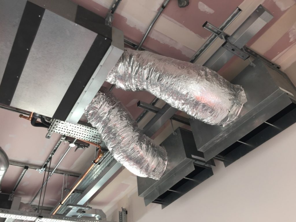
The use of flexible air ducts is kept to short lengths to minimise duct pressure loss.
Photo taken at Custom House Station
1.26 Access panel for air duct

Access panels are installed to facilitate maintenance and inspection access to ductwork and equipment.
Photo taken at Farringdon Station
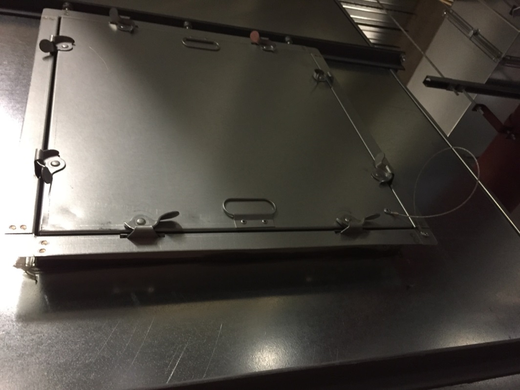
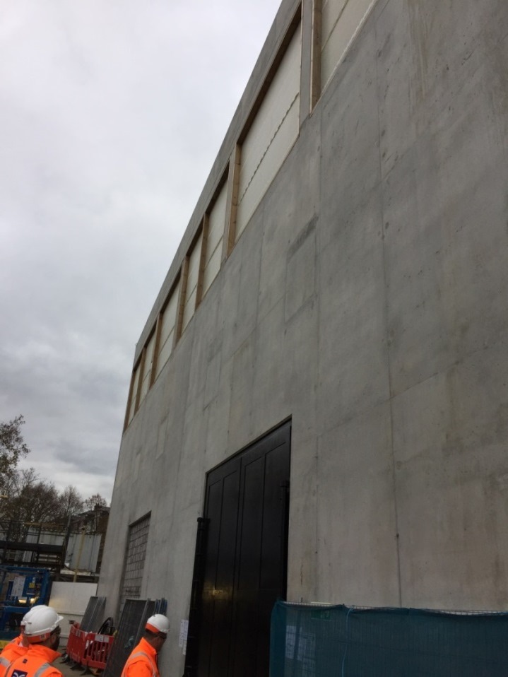
1.27 Access panel for fire rated reinforced concrete service plenum
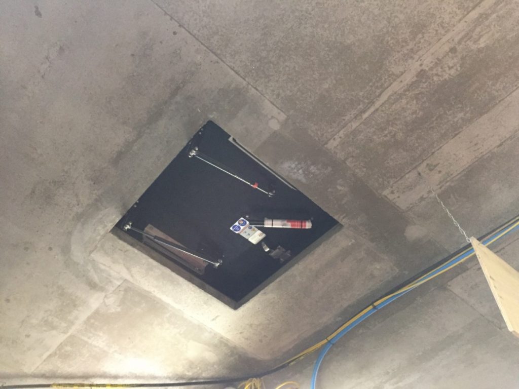
Proprietary fire rated door with hydraulic door gears is provided for maintenance access to the overhead service plenum.
Photo taken at Liverpool Station
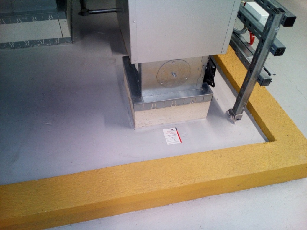
1.28 Floor mounted motorised fire and smoke damper

All floor fire stoppings were installed by specialist contractor and clearly labelled.
Photo taken at Canary Wharf Station
1.29 Wall mounted Fire and Smoke Damper and support
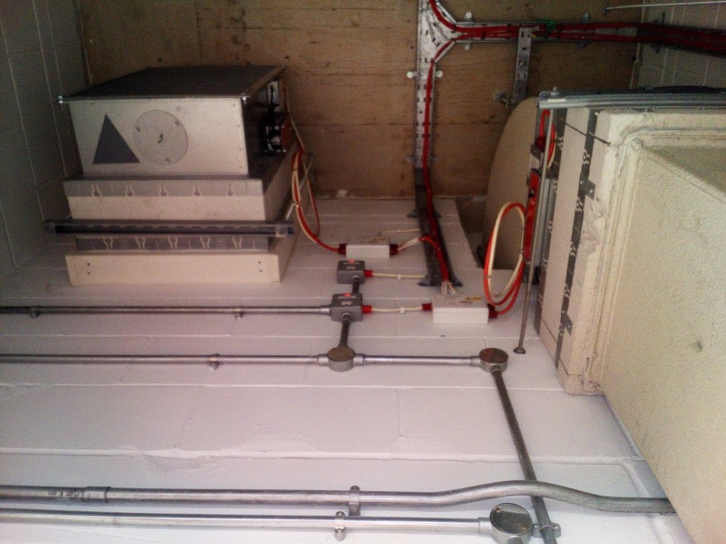
Photo taken at Canary Wharf Station
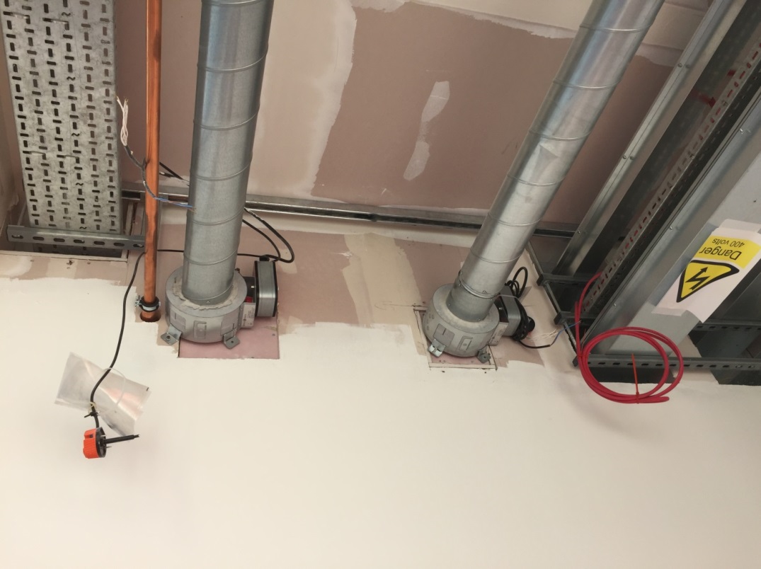
1.30 Motorised Fire and Smoke Dampers and Supports for circular air ducts
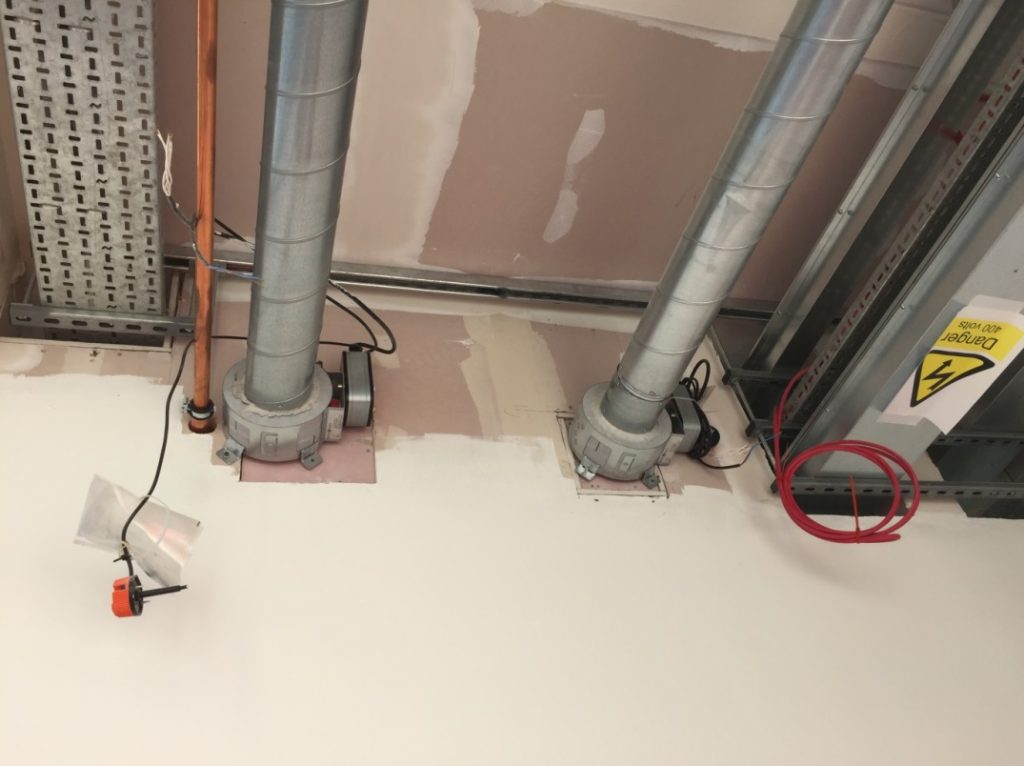
Wall mounted in accordance with supplier installation instructions. Temperature probe shown here is yet to be installed.
Photo taken at Custom House Station
1.31 MEP Service Riser (1 of 2)
There are two types of service risers in Crossrail: (a) Open type- the entire riser is a single fire compartment. (b) Closed type- a separate fire compartment is provided at each floor. An open type riser is shown here.
Photo taken at Tottenham Court Road Station
1.32 MEP Service Riser (2 of 2)
There is no fire barrier between floors. The riser walls form the fire barrier.
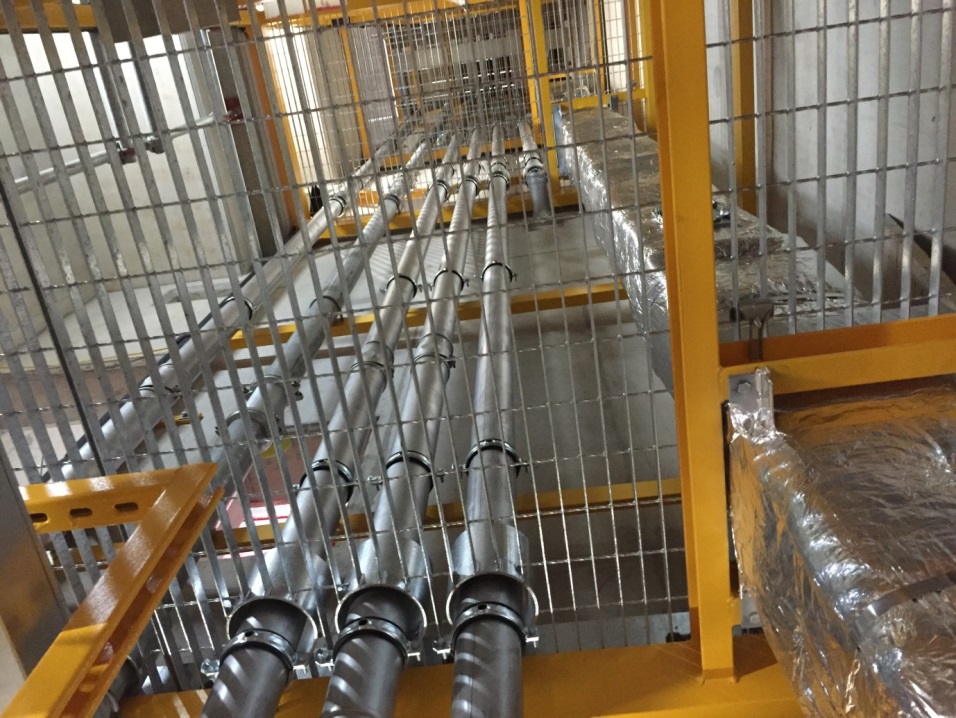
Photo taken at Tottenham Court Road Station
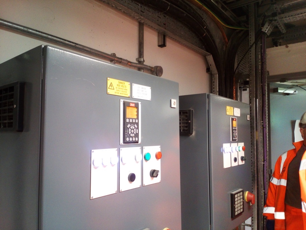
1.33 Motor Control Cubicle (1 of 2)
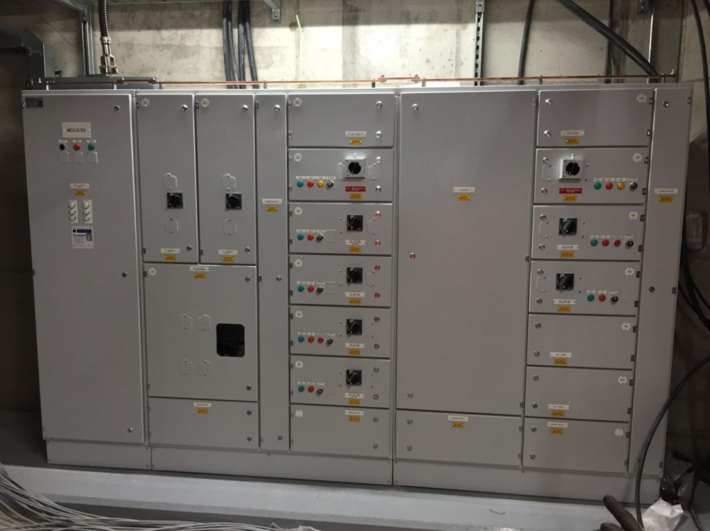
In Crossrail stations, all of the motor control cubicles and control enclosures are of front access design. Attention was made in the construction design to ensure that maintenance access is provided to key components of the panel and that thermal scan, as an inspection tool, is possible to the bus bar chambers.
Photo taken at Liverpool Street Station
1.34 Motor Control Cubicle (2 of 2)
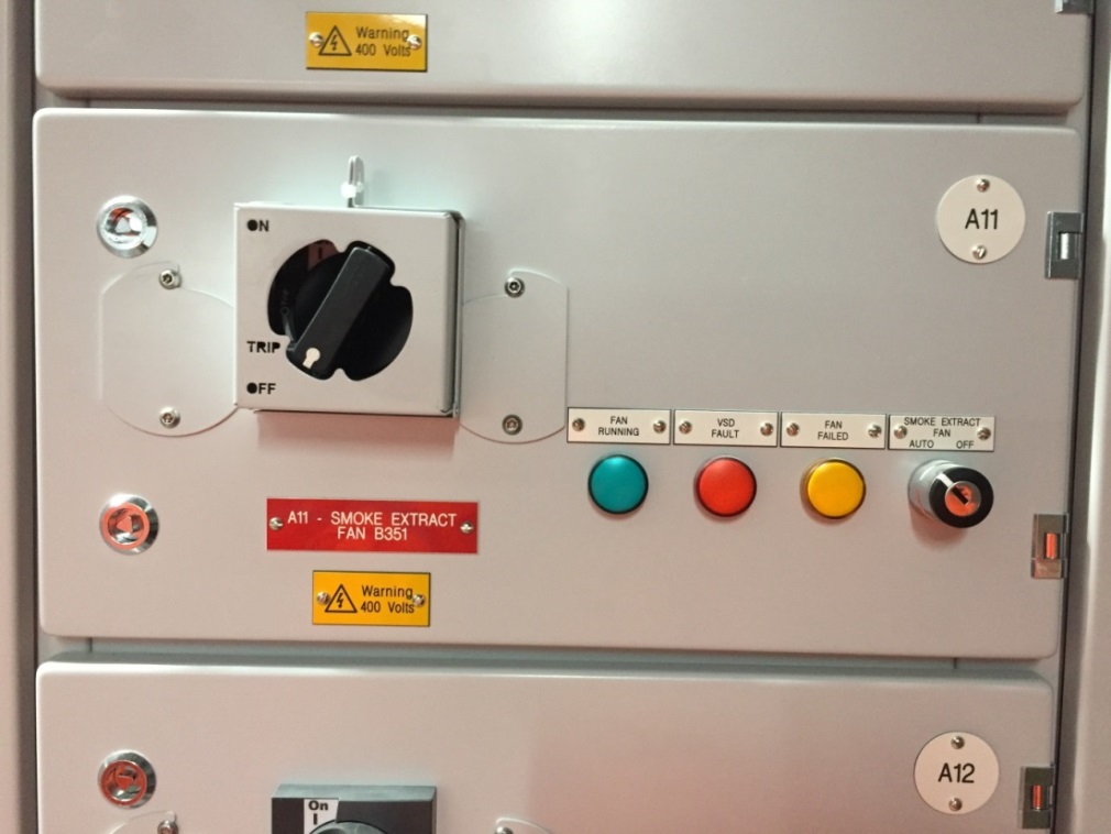
A separate compartment is maintained for each motor assembly. The compartment contains isolator switch, control switch (auto-off) and indication lights. The variable speed drive is not part of the cubicle for this installation.
Photo taken at Liverpool Street Station
1.35 Motor Control Panel
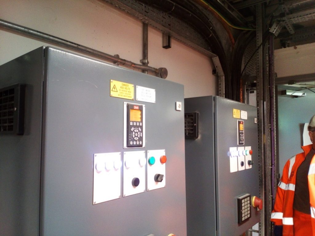
Wall mounted motor control panel.
Photo taken at Canary Wharf Station
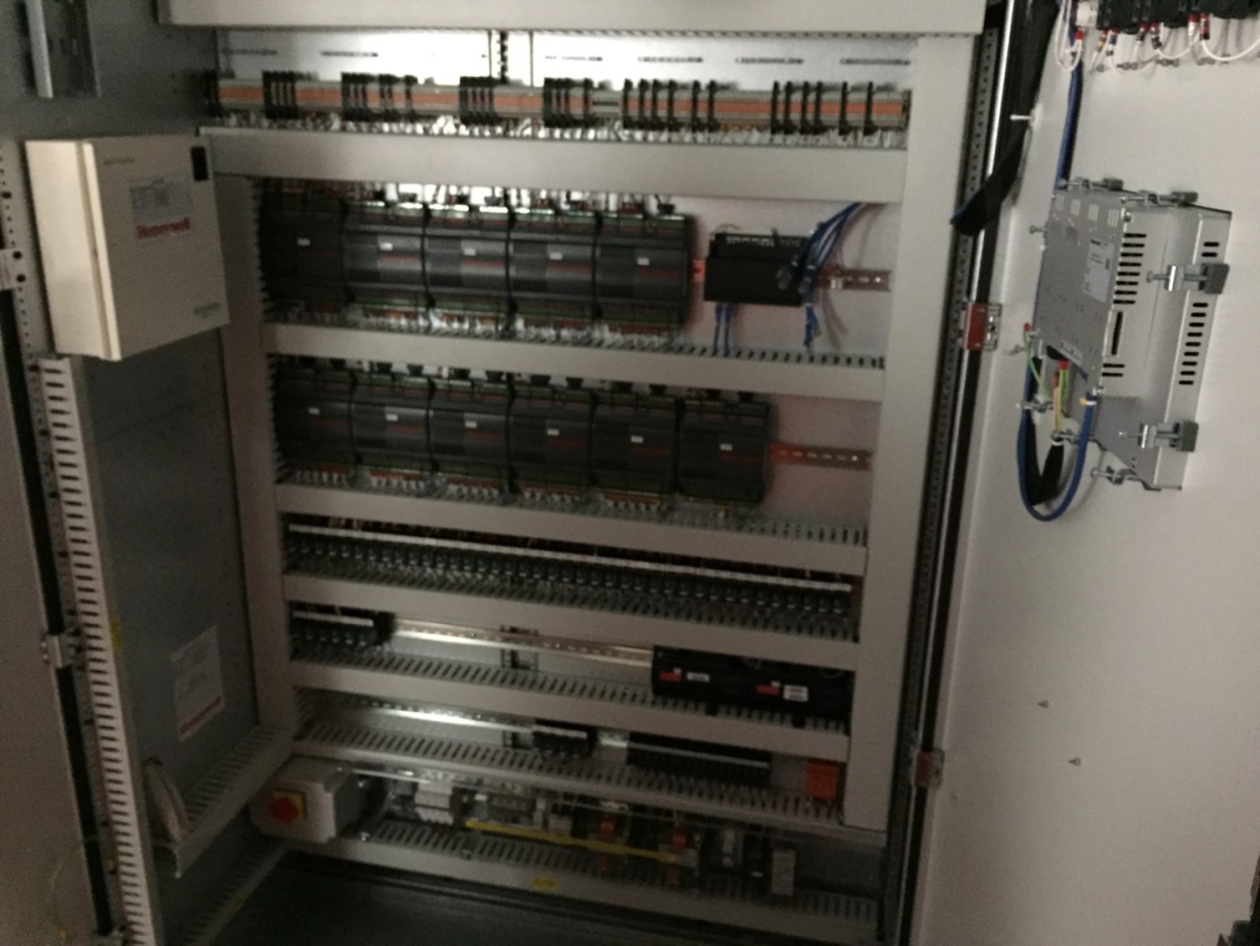
1.36 Control Enclosure

The control enclosure houses the process controllers, control relays and input/ output ports for the mechanical system.
Photo taken at Liverpool Street Station
1.37 Concealed control panel in public areas
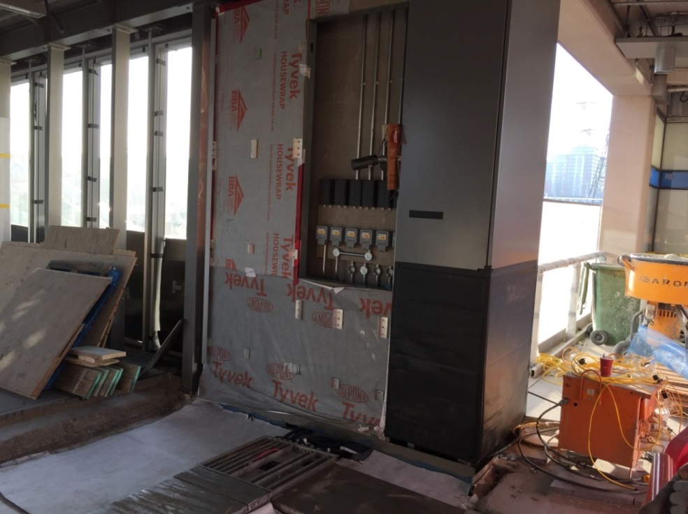
The panel provides access to local switches and connection boxes.
Photo taken at Custom House Station
1.38 Air relief damper at the pressurised fire brigade intervention staircase
The air relief damper is an integral part of the pressurisation system for the intervention staircase to control the pressure level in the stairwell.
Photo taken at Canary Wharf Station
1.39 Sump Pump assembly
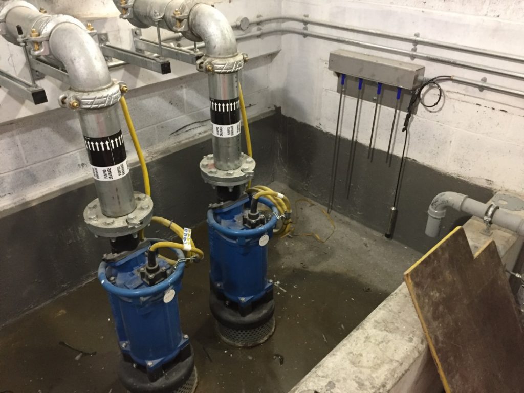
Photo taken at LUL Bond Street Station (Bond Street Station Upgrade Project)
1.40 Sump Pump control panel

The control panel houses the motor control and process control (pump change over and sump level control) elements of the sump pumps. Remote condition monitoring is provided by the station building management system or SCADA system.
Photo taken at Liverpool Street Station
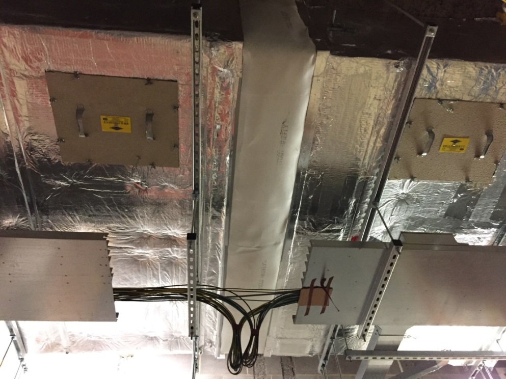
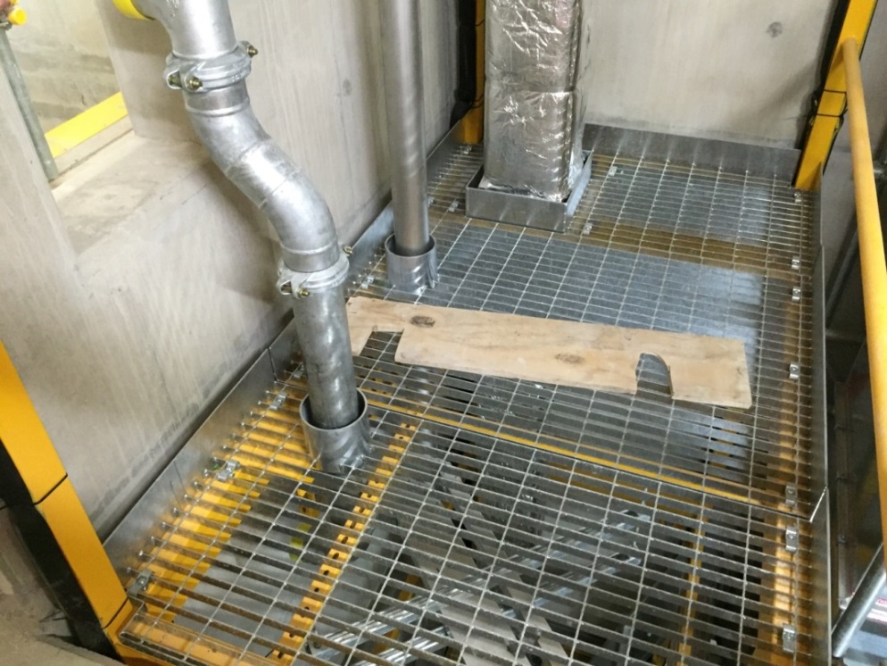
1.41 Earth gap (duct)
The earth gap is provided to ensure positive segregation of the part of the air duct which is connected to the traction earth system and the remaining section which is connected to the station earth system.
Photo taken at Liverpool Street Station
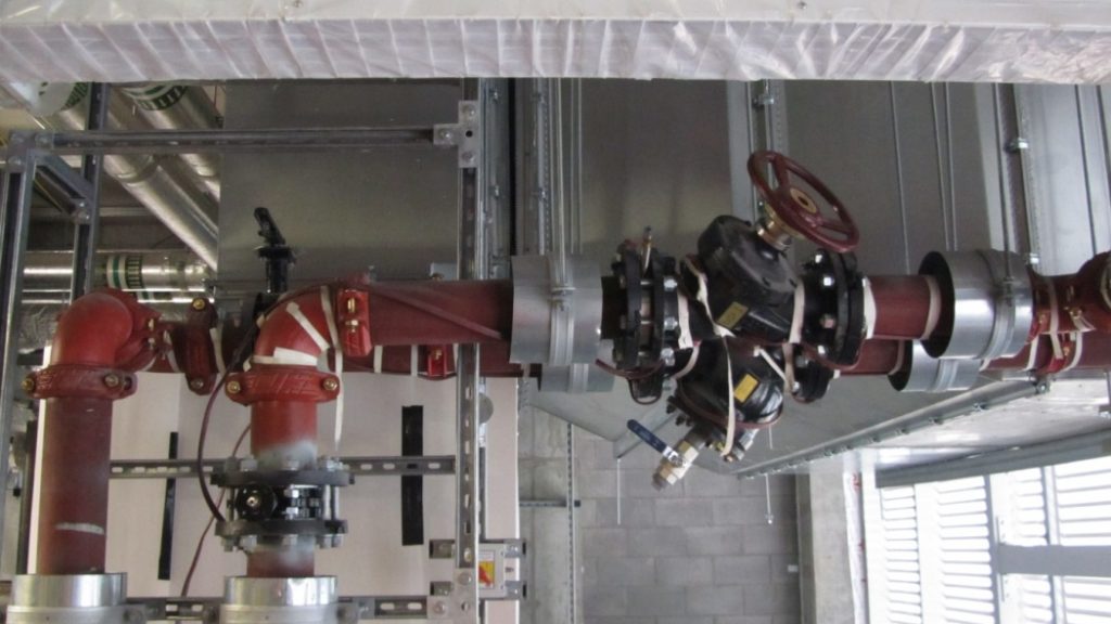
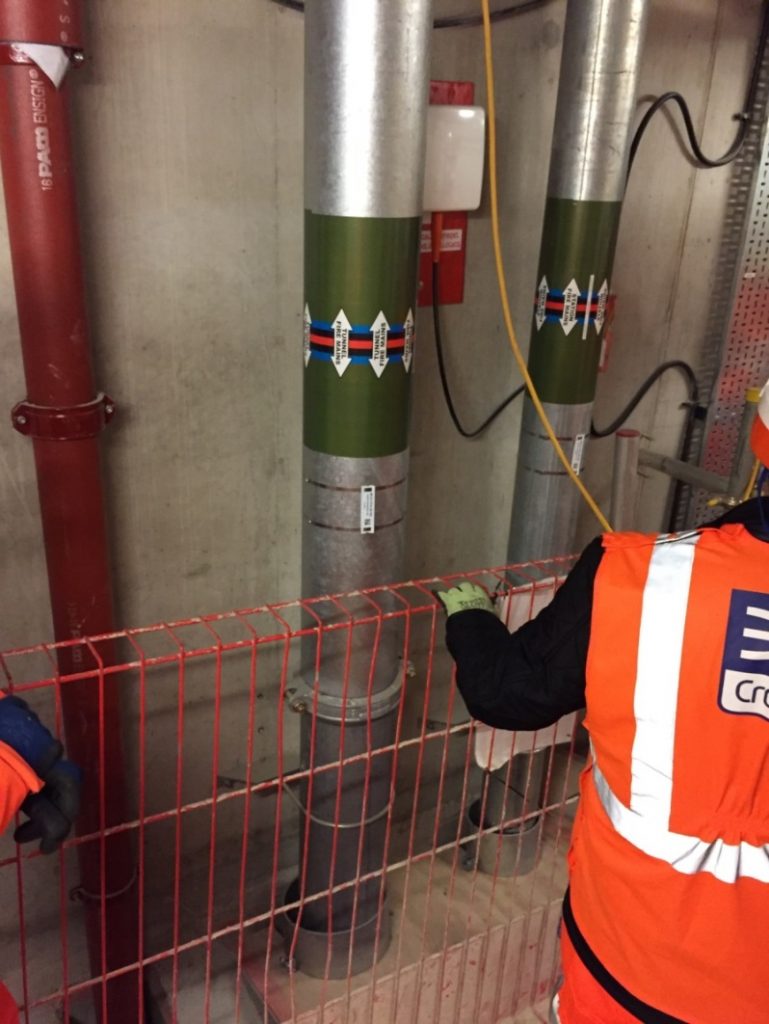
1.42 Earth gap (pipe)
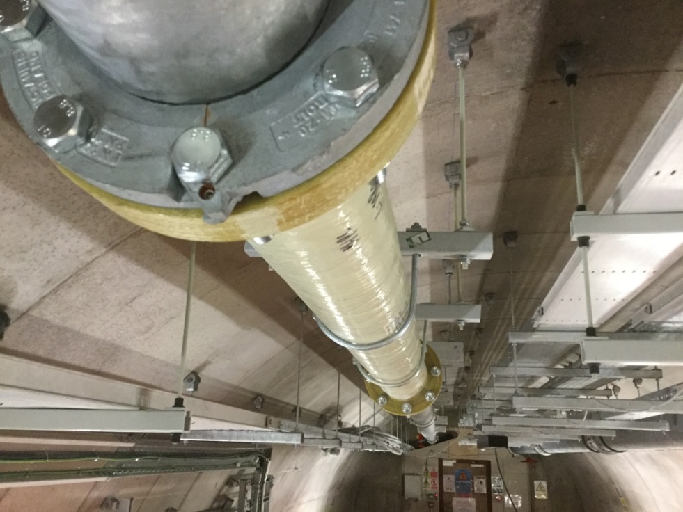
The non-conductive earth gap is provided to ensure positive segregation of the part of the fire hydrant pipe which is connected to traction earth system and the remaining section which is connected to the building earth system. The top support rods are also of non-metallic construction.
The adjacent cable trunking is also provided with similar non-conductive earth gap section.
Photo taken at Eleanor Street Shaft
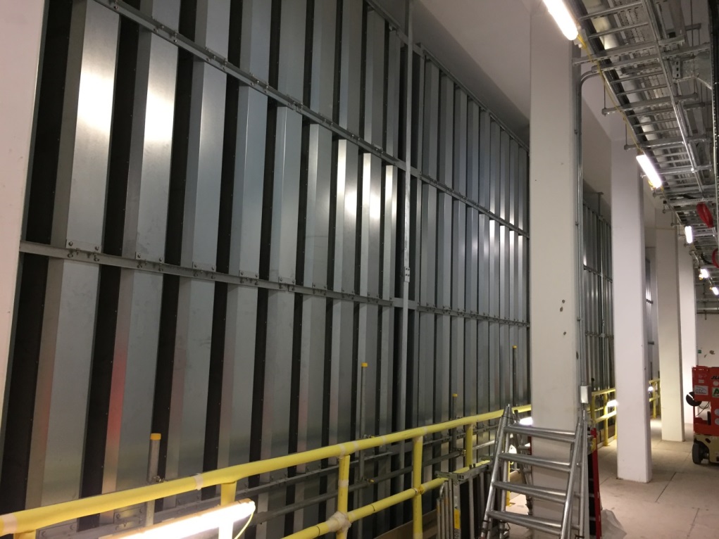
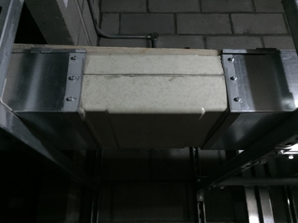
1.43 Air plenum
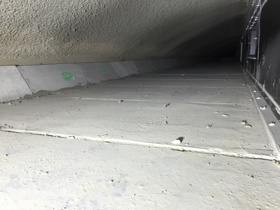
Part of the building structure is sometimes enclosed to form an airway for ventilation. Air leakage and frictional losses are some of the primary concerns on the effectiveness of the airway. The photo shows part of the over-track platform smoke extract plenum. Sealing of joints and pressure tests were carried out to ensure the airway is fit for use.
Photo taken at Bond Street Station
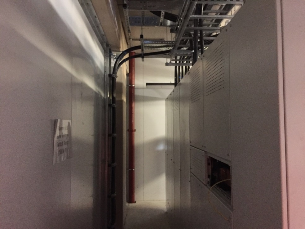
1.44 MEP Maintainability and Accessibility (1 of 4)
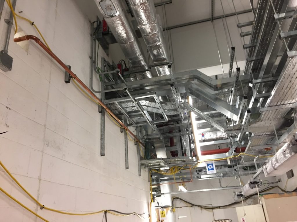
Because of design requirements, it is inevitable that mechanical, electrical and public health services have to share a common service corridor. Detailed design and site co-ordination have to be made to ensure that adequate maintenance access is provided and that operational safety issues are addressed (e.g. any leakage of water pipes will not be detrimental to the nearby electrical services).
Photo taken at Woolwich Station
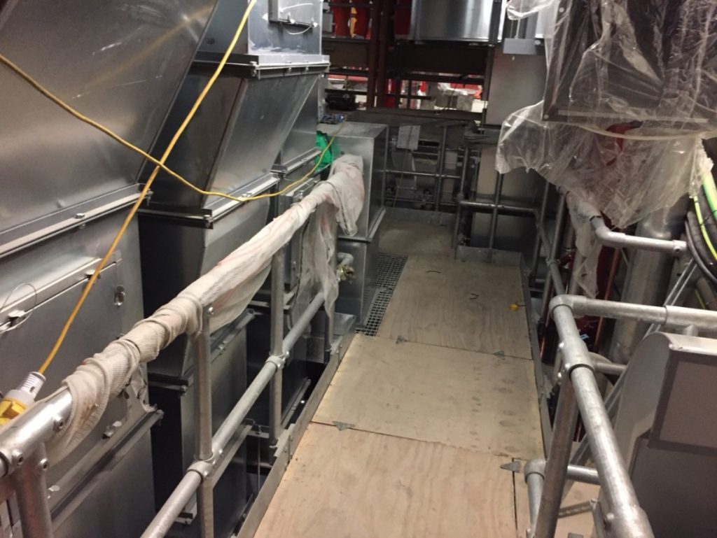
1.45 MEP Maintainability and Accessibility (2 of 4)
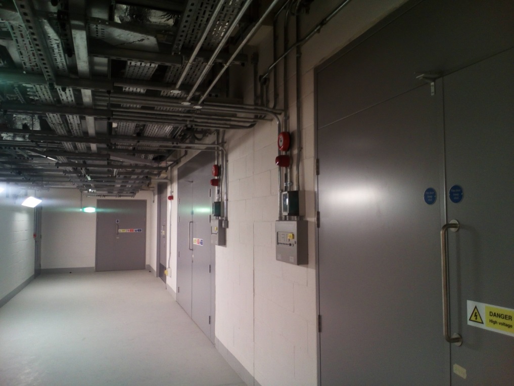
Adequate width of the service corridor in the back of house areas is needed for delivery of equipment and accommodation of MEP services in the area.
Photo taken at Canary Wharf Station
1.46 MEP Maintainability and Accessibility (3 of 4)
Maintenance access space is allowed for back access to the electrical cubicle.
Photo taken at Farringdon Station
1.47 MEP Maintainability and Accessibility (4 of 4)
Elevated maintenance walkway is provided to facilitate access to equipment at height that requires regular access.
Photo taken at Farringdon Station
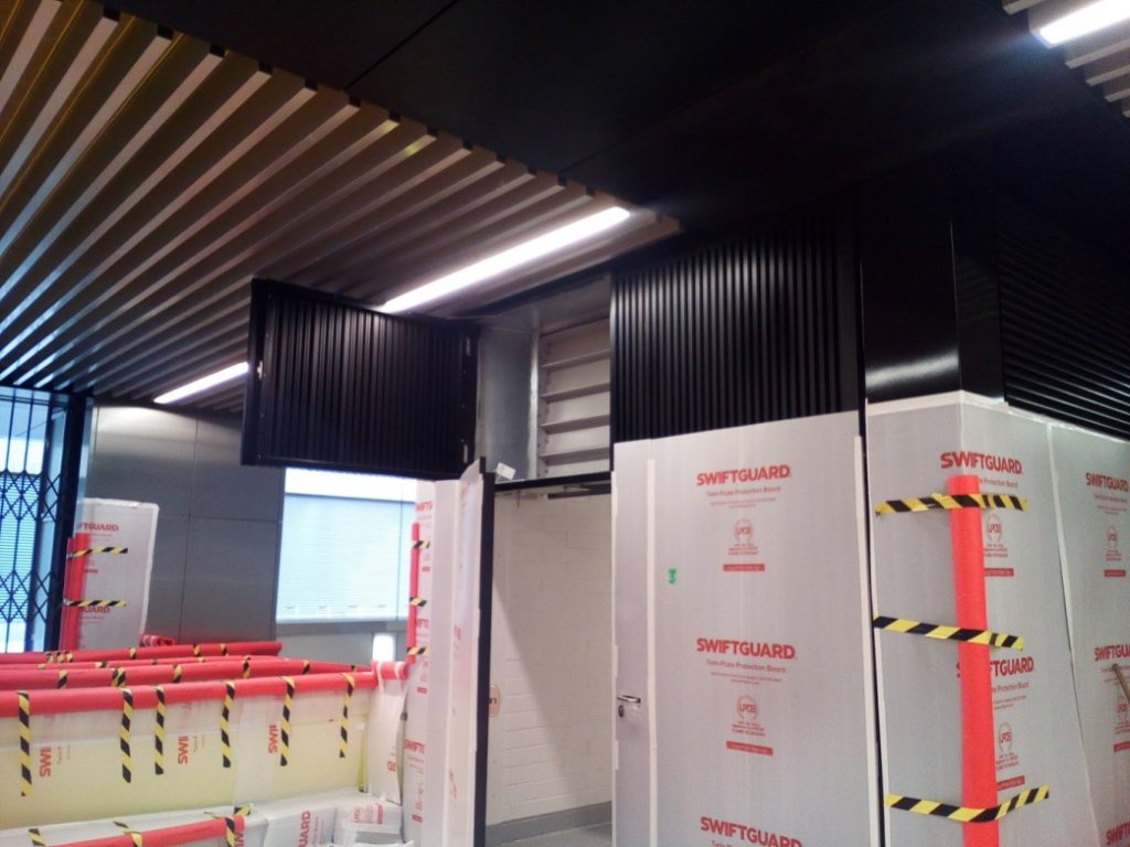
1.48 Temporary Protection of equipment

An acceptable fire safety material (to LPS1207) is used for temporary protection of site equipment.
Photo taken at Tottenham Court Road Station
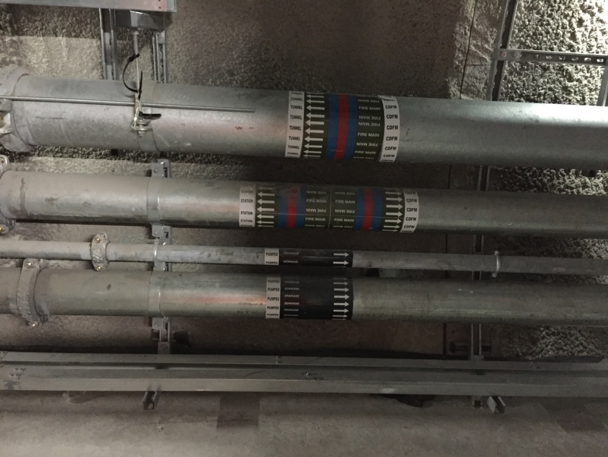
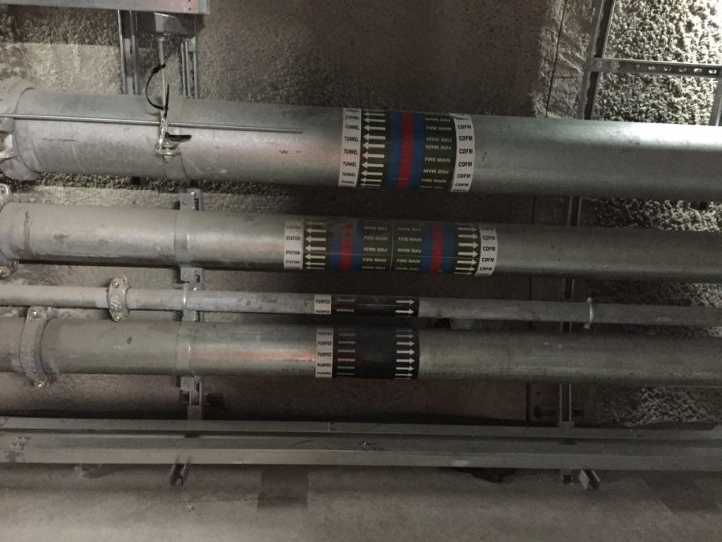
1.49 Service Labels (1 of 2)
Standardised labels provided for pipe services to show the type of service and flow direction.
Photo taken at Farringdon Station
1.50 Service Labels (2 of 2)
Standardised labels provided for pipe services to show the type of service and flow direction.
Photo taken at Liverpool Street Station
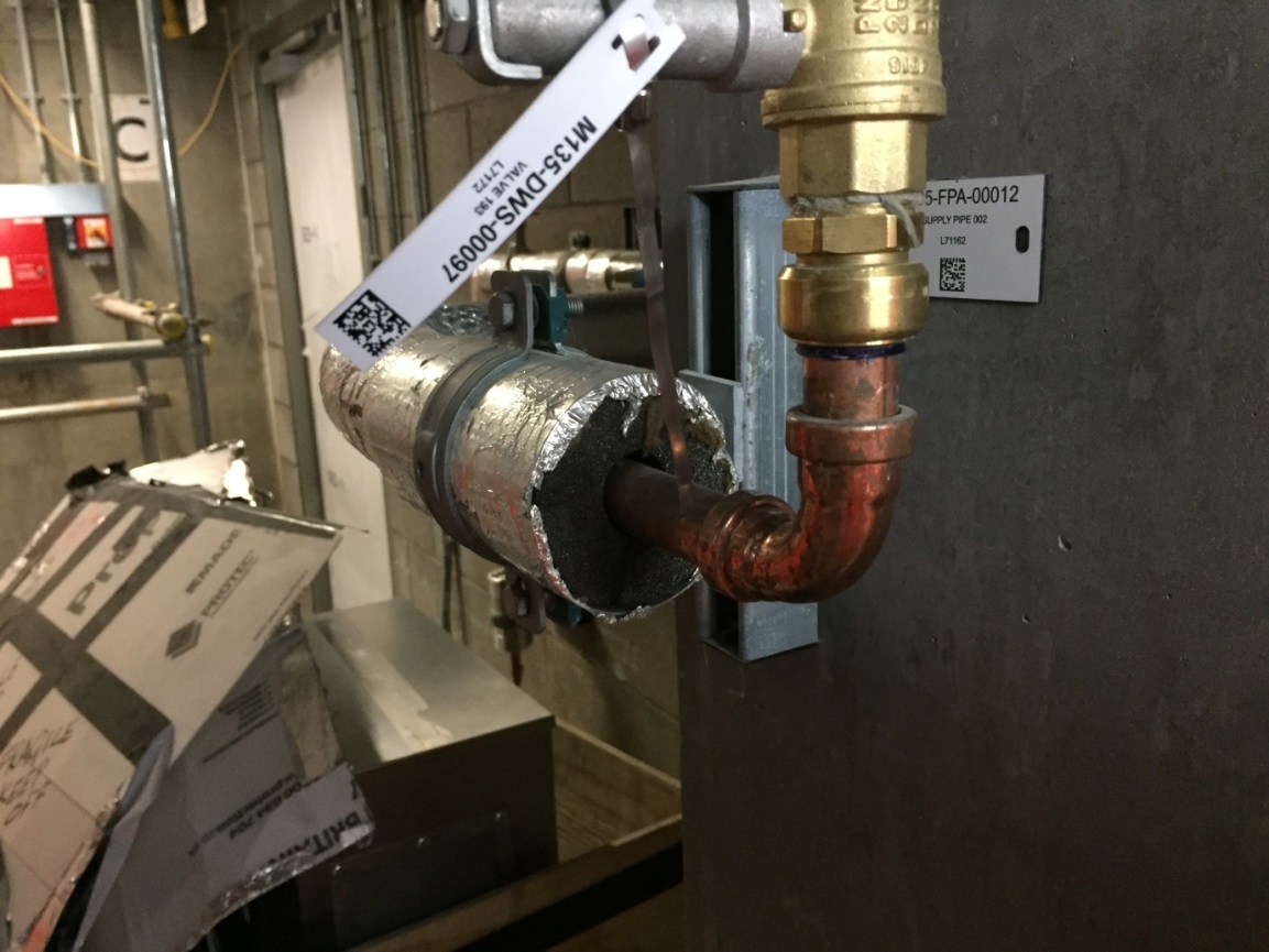
1.51 Asset Tags

Standardised labelling system provided for asset identification. In Crossrail, the asset identification system is linked up to the O&M manual and maintenance management systems.
Photo taken at Liverpool Street Station
-
Authors
Wing Fung PhD MSc BSc(Eng) CEng MCIBSE - Arcadis
Technical Director (MEP), Arcadis
Wing is is a Chartered Engineer with over 30 years’ experience as a technical specialist engaged in mass transit system planning, design, project management, technical assurance, commissioning, energy management, operation and maintenance, and asset renewal. Wing has been with the Crossrail project in the CRL Chief Engineer Group since 2013, overseeing mechanical design, systems integration and T&C.
Specialties: Building Services, Mechanical Engineering, Computational Fluid Dynamics, RAM studies, Systems Integration, Requirement Management, Testing and Commissioning.