Specification & standard implementation across Crossrail contracts
Document
type: Technical Paper
Author:
Chris Robinson
Publication
Date: 10/11/2015
-
Read the full document
Introduction
Through their involvement on a significant number of Crossrail contracts involving construction of embedded retaining walls, Cementation Skanska Limited (CSL) have had the opportunity to experience a variety of approaches adopted across these works, and compare good experiences with those which were, perhaps, rather more challenging.
This paper will describe the principal areas where greater consistency and communication across the entire project may have enabled more effective sharing of best (and emerging) practice across all parties involved in the project, from the Client to material suppliers, and afforded the project enhanced quality of delivery and greater economies.Reinforcement cage detailing
General considerations
Details for reinforcement cages such as anchorage projection length, lap lengths, location of lapped bars & couplers (staggered or otherwise), and bond condition, was one area where considerable discussions were had with the Design Engineer on most of the contracts on which CSL worked (although the Crossrail Civil Engineering Design Standard is explicit on some of these points). When CSL undertook their first Crossrail contract works at Royal Oak Portal, the majority of the UK construction industry had relatively little implementation of Eurocode requirements (BS EN 1992-1-1: 20041) for these reinforcement details.
One of the more contentious issues was that of the definition of “good” bond conditions (although the Crossrail Civil Engineering Design Standard is explicit on this point). On the early contract works undertaken by CSL there was an assumption that for any element constructed under bentonite support fluid then “good” bond conditions did not apply and therefore a greater lap / anchorage length was required. This is contrary to previously published guidance e.g. codes of practice BS81102 and BS54003, and also guidance within published papers, e.g. Jones & Holt 20044, although there was also existing published information agreeing with the adoption of “poor” bond conditions when designing to EC 2 (BS EN 1997-1-1: 20041) since EC2 explicitly considers the potentially beneficial effect of enhanced cover to the lapped reinforcement bars. The situation was therefore somewhat confused. An additional detail to consider is the magnitude of bar stress at the level of the lap (or anchorage length) which could potentially significantly reduce the lap length if this were to be calculated rather than a generic “worst case” multiplier being adopted (although this is arguably significantly less burdensome to the designer / detailer). EC2 (and relevant execution standards) does state that laps should not be located in zones of high moment (Cl 8.2.2), lap lengths derived assuming fully stressed bars together with partial factors such as a material factor, c, for concrete of 1.65 (for foundations) could be adding considerable conservatism into the reinforcement detailing solution.
Below is a typical extract from a Crossrail “General notes” drawing. This states the required number of bar multiples depending on the vertical location within the element (pile / panel) and also differentiates between bar sizes of 32mm or smaller, or 40mm. This is at variance to the guidance contained within the UK national annex (NA to BS EN 1992-1-1: 20045) Table NA.1 subclause 8.8(1) which states large bars are those bars which are greater than 40mm diameter. The value of η2 adopted will affect the design values of ultimate bond stress and therefore the lap or anchorage length required.
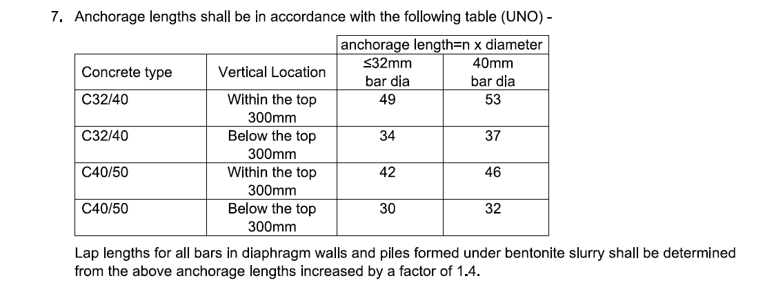
Figure 1 – Extract from typical Crossrail “General notes” drawing
Where 50mm diameter reinforcing bars were used these were required to be coupled rather than being spliced, with the coupler levels being staggered, although it should be noted that EC2 (cl 8.8) does make provision for lapping of “large bars” (i.e. >40mm as defined by NA to BS EN 1992-1-1: 20045) where the section has a minimum dimension of 1m or the reinforcement stress is less than 80% of the design ultimate strength.
Diaphragm wall reinforcement cages
The reinforcement cage detailing for diaphragm wall panels needs to consider many aspects including the main (longitudinal) reinforcement requirement, shear links, inclusion of couplers or other slab connection details (e.g. Kwikastrip / pull-out bars), bar congestion (to facilitate flow of fluid concrete / “clean” bentonite), cage assembly methodology, couplers / splices for connecting sections of reinforcement cages within individual panel). Many of these factors can be in conflict to each other and all must be considered to derive the optimal solution to achieve the design requirements together with the required level of quality.
On the diaphragm wall works undertaken by CSL there were differences in how the Design Engineer communicated reinforcement requirements. On the one hand fully detailed reinforcement cage drawings were provided which, in principal, could have been sent for fabrication with no further input from the specialist contractor. The contrasting scenario was where design intent reinforcement drawings were provided with the detailing to be undertaken by the specialist contractor.
Whilst the former situation sounds more attractive for the specialist contractor, CSL’s experience is that there was generally insufficient consideration of the fabrication process (in terms of the approach preferred by CSL) for this to represent a sufficiently safe proposition. Consequently, in the cases where CSL were provided fully detailed reinforcement drawings, these were re-detailed principally to suit the fabrication processes being adopted, although there were situations where cage congestion could be alleviated through factors such as re-locating laps /splices.
The detailed design of diaphragm wall reinforcement cages should consider how the cages are to be fabricated including consideration such as whether closed or open shear links are more appropriate (Ref. ICE Temp works: Principles of design and construction, Chapter 136).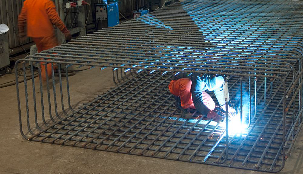
Figure 2 – Historic image showing closed link diaphragm wall cage fabrication
As is illustrated in Fig 2 above, adoption of closed links makes the fabrication process significantly more onerous for the operatives involved.
An additional consideration is whether the reinforcement cages are to be fabricated off site and transported to site (which will significantly constrain the maximum length and width of the diaphragm wall cages), or if on-site fabrication is possible, which will facilitate construction of diaphragm wall panels up to 7m long, and significantly longer reinforcement cages (further reducing risks associated with splicing cages, although there may be increased lifting risks associated with tandem lifts). Both situations were encountered across the works undertaken by CSL, typically the portal structures were located on larger sites which could accommodate on-site fabrication, whereas the station boxes and access shafts were located on sites with a much smaller footprint.
BS EN 1538: 20107 does state minimum clearances between adjacent reinforcement bars in the vertical and horizontal planes. One area which can often appear to be overlooked however, is the effect on cage congestion through the introduction of additional reinforcing elements such as lacer bars for couplers at the location of slabs / skin (liner) walls. These can locally significantly increase the reinforcement cage congestion which potentially can have a significantly detrimental effect on the quality of the finished product, e.g. mattressing of concrete due to inadequate flow through the reinforcement (typically manifesting at the near face of the diaphragm wall panel) or inclusions within the body of the panel due to inadequate displacement of the bentonite support fluid.
Rotary bored piles –“super-reinforced” cages
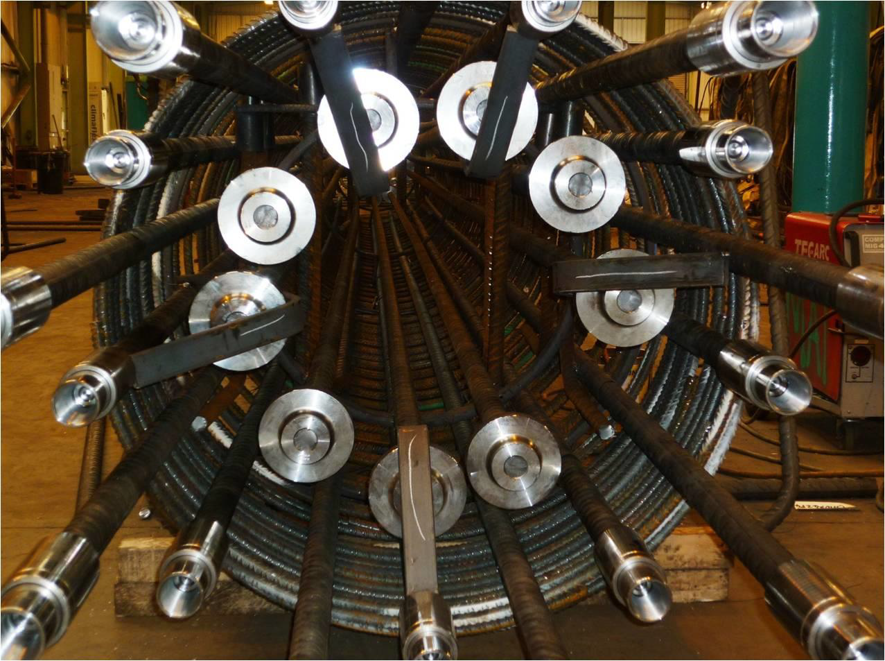
The Bond Street Eastern ticket hall required male secant piles to be reinforced over part of their length with a double layer of longitudinal reinforcement. The detail was referred to as the “super-reinforced” section. This detail pushed the limits of CSL’s reinforcement fabricators and required careful consideration of how to effectively enable the sections of pile cage (overall pile cage lengths were up to around 40m long) to be spliced together at / over the super-reinforced section. The detail that was developed involved the use of terminator couplers at the top and bottom of the internal reinforcement cage (See Fig. 3 below). This detail negated the requirement for complicated double staggered laps at the top and bottom of these cage sections which would have been exceedingly difficult to connect and would have introduced significant additional risks to the operatives involved in the splicing process.

Figure 3 – “Super-reinforced” secant pile reinforcement cage
An additional consideration when detailing the “super-reinforced” section of the secant pile reinforcement cage was to ensure that the risk of snagging the tremmie pipes during the concreting process was minimised. The use of terminator couplers, whilst negating the requirement for the double staggered laps, introduces a greater risk of snagging the tremmie pipes since by their very nature of providing a mechanical anchorage for the internal cage creates an effective lip which could catch on the joint of the tremmie pipes. A simple solution was adopted whereby a shaped flat steel “bar” was installed over sufficient terminator couplers to effectively guide to tremmie pipe around the terminator couplers when they were installed or extracted during concreting. This simple solution proved to be highly effective.
Cased CFA piles
The reinforcement cage lengths required for a cased CFA secant wall at Plumstead portal (part of the C310 contract) pushed the limits of what would be considered within the normal range. At Plumstead 18.5m were detailed which needed to be plunged full length into the fluid concrete forming the male piles immediately following the concreting process. This requirement within bearing piles would have presented a much lower risk profile for two principle reasons; 1) the 300mm cut into the female piles would create significant heat which could cause an increased rate of concrete hydration, and 2) bearing piles typically give more scope for remedial measure either through design review or, at worst case, introduction of replacement / additional piles.
There were two additional factors which further increased the risks associated with constructing the cased CFA secant piled wall, 1) slab couplers were specified to tie the base slab into the secant wall, and 2) the reinforced pile length was 18.5m. At 18.5m length the reinforcement cages would have needed to be spliced since the maximum stock length of reinforcing bar is 18.0m which when combined with the requirement for slab couplers would have increased the resistance to plunging the cages to the required level significantly.
CSL therefore requested a change to the design requirement to limit the reinforced pile length to 18.0m and to replace the cast in slab couplers with a drill and fix solution following excavation of the portal. These changes were ultimately adopted. Out of around 300 No. male cased CFA secant piles installed at the Plumstead Portal, all except two successfully had the 18m long reinforcement cages installed. The two pile which experienced issues with plunging the cages were the first two male piles to be constructed, and modifications to the concreting process, essentially to control the age and therefore stiffness of the “fresh” concrete, lead to the successful construction of all remaining male piles.
At 300mm the size of the cut into female piles required for the cased CFA secant wall at Plumstead portal was beyond the conventional norm for rotary piling, and was certainly greater than had been previously undertaken by CSL using cased CFA techniques. Using a Bauer BG40 rig fitted with Bauer’s DKS cased CFA equipment the cut was successfully achieved with a lower rate of wear on the segmental casing than had been anticipated from experience.
Integrity testing of embedded retaining wall elements
Across the contracts on which Cementation Skanska worked, there was a lack of consistency in the approach taken for integrity testing of embedded retaining walls elements, in particular diaphragm wall panels. This very much depended on the Design Engineer for each contract, rather than the particular characteristics of the contract (e.g. ground conditions or construction methodology). Extreme examples would be a diaphragm wall box to the West of London constructed almost entirely within London Clay which was required to have sonic logging tubes installed in every panel compared to a diaphragm wall portal to the East of London constructed through soft alluvial deposits, peat, river terrace gravels and chalk for which no sonic logging tubes were required (indeed no integrity testing at all was specified or required to be undertaken).
The inclusion of sonic logging tubes within reinforcement cages is potentially problematic, particularly from a safety perspective where sections of reinforcement cage need to be connected together, since operatives have to place their hands within the reinforcement cages, the upper section of which is of necessity suspended from a crane and therefore potentially subject to unplanned vertical movements. Where this risk can be eliminated it is incumbent upon all those involved in such works to ensure that this is achieved.Alternatives to sonic logging are increasingly being adopted due to their inherent safety advantages as well as there being greater industry confidence in these alternatives. The principal alternative is a technique known generically as thermal integrity testing. This is a method whereby the heat of hydration is measured at various points within the cross section of the element (e.g. pile or diaphragm wall panel). The quality of the constructed element is assessed from the temperature across the section, with greater temperature consistency being indicative of a high quality defect free (or low defect) product. Areas of lower temperature would tend to indicate inclusions or a reduction in cross sectional geometry local to the monitoring location, whereas areas of higher temperature would indicate areas of increased cross section (e.g. significant overbreak).
Due to the method relying on the heat of hydration, there is clearly a greater time constraint when adopting this method than with sonic logging or low strain techniques, but this constraint should be easily managed though a well developed and implemented planning process. This technique also enable early results to be obtained, typically within 48 hours of pile concreting being completed.
Headwall details
The tunnel portals constructed as part of the C310 contract (Plumstead and North Woolwich) required soft panels to be constructed behind the main structural headwalls to assist the TBM launch processes, in particular to improve “watertightness” to reduce the potential for water / slurry ingress through the headwall as the TBM’s launched through the headwalls.
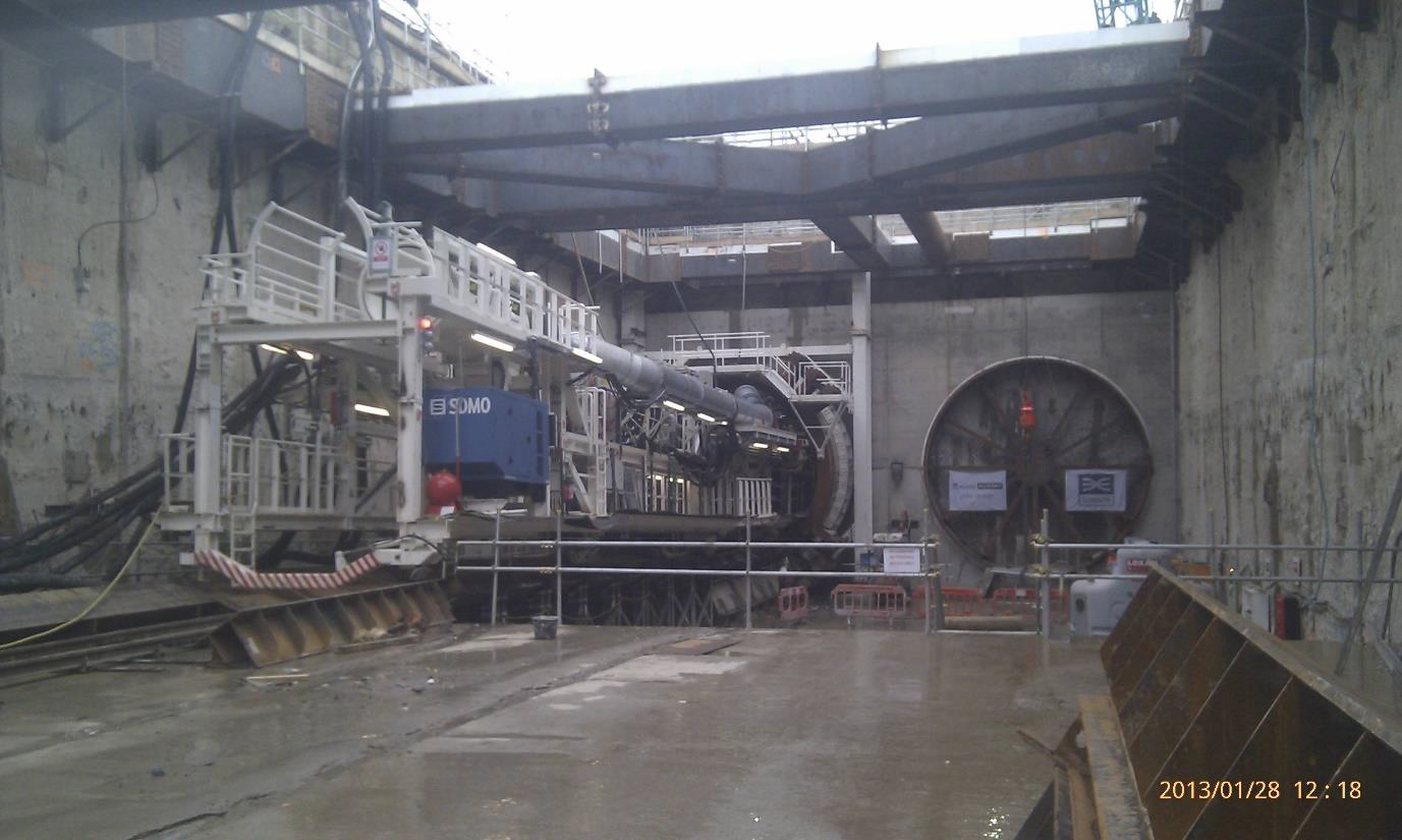
Figure 4 – C310 Plumstead Portal / Headwall
At the Plumstead portal “soft” panels behind the headwall were constructed prior to the main structural headwall. These “soft” panels were located such that there was around 50mm overbreak into structural panel zone (ostensibly to allow the structural panel to be in intimate contact with the “soft” panel to reduce the risk of groundwater flow between the two panels). However the “soft” panel exhibited a much greater strength gain than planned (as validated by early trial mixes), which when combined with the deliberate over break / encroachment into the main structural headwall zone, caused some difficulties with maintaining correct panel (grab) alignment.
At the North Woolwich portal the “soft” panel behind the headwall were constructed after main structural headwall panels. CSL used a brush arrangement to clean the back of the main structural headwall panel to ensure there was intimate contact between the two panels. This approach worked well and with less issues than experienced at Plumstead.
The requirement or otherwise, for the construction of soft panels immediately outwith the main structural headwall will depend on a number of factors, not least, the prevailing ground conditions, the tunnelling method being adopted, and the risk management strategy being employed by the tunnelling contractor.
Soft eye details
Generally the soft eye details adopted were simply a replacement of the conventional steel reinforcement with glass fibre reinforced polymer (GFRP) with temporary works steel to facilitate lifting and placing. GFRP was adopted over the soft eye zone since this can be readily cut through by the TBM when exiting or entering the portals, boxes or shafts. This is a relatively standard process common to these types of infrastructure schemes.
However, on the Paddington station box contract the requirements were quite different. At Paddington the TBM drives were to be undertaken prior to the box being excavated and fully formed (a function of the scheme TBM drive programme in relation to the station box construction). The original concept adopted by the Design Engineer was to install a “soft” secant wall at each of the four entry / exit locations within end walls of the station box (to provide ground support to allow the tunnel eye structure to be constructed when the station box was excavated) with diaphragm walls being constructed to form the main structural box.
The “soft” secant wall was proposed to be located part over the plan position of the diaphragm wall (see Fig 5 below for the general configuration), with the secant wall being constructed prior to the diaphragm wall. The diaphragm wall at the secant wall positions was to be of limited depth, around 16m, the box excavation being around 25m deep) such that the TBM would pass beneath the toe of the diaphragm wall panels and pass relatively unimpeded through secant wall which was to have similar strength characteristics to the in-situ London Clay. In essence the “soft” secant wall was to allow the TBM’s progression to be unaffected but to provide a greater consistency of material than the in-situ London Clay may have had.
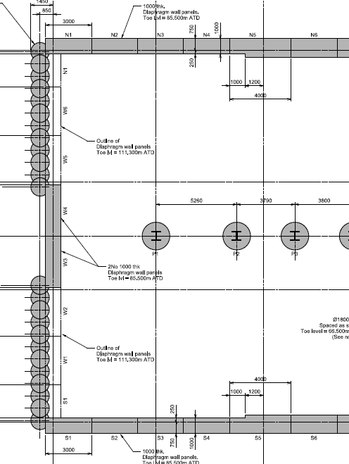
Figure 5 – “Soft” secant wall / diaphragm wall arrangement
The “soft” secant wall’s position relative to the immediately adjacent diaphragm wall panels was of concern to CSL since there was considered to be a high risk of the diaphragm wall panel kicking off the secant wall into the station box. An alternative solution was therefore proposed, whereby “soft” diaphragm wall panel would be installed at the four TBM entry / exit locations at the exact location where a structural diaphragm wall would subsequently be installed (again to a limited depth of around 16m). The general configuration of the “soft” panel and structural panel are indicated in Fig. 6 below with the “soft” panel section shown in orange and the structural panel shown in grey.
This alternative proposal was adopted, however only one such configuration was constructed before a significant re-sequencing of the station box construction was required. As one method of reducing the critical path elements of the station box construction, CSL proposed that the remaining three soft panel construction zones be omitted in entirety, with only the relatively shallow structural diaphragm wall being formed. Since the “soft” panels were designed to give similar properties to the in-situ London Clay, there seemed to be little benefit from installing these if a sufficiently robust risk management plan could be introduced (e.g. use of the observational approach with sufficient mitigation measures such as temporary shoring, grouting etc. being put in place). This proposal was ultimately adopted and enabled the diaphragm wall construction works to be reduced by around one – two weeks.

Figure 6 – “Soft” panel / structural panel headwall configuration
Where similar construction details and ground conditions apply, this methodology should be considered from the outset rather than introducing complicated and relatively onerous construction details.
Conclusions
Whilst early contractor engagement was undertaken on the Crossrail project, one area which could be improved would be to ensure that the information received through this process does not get “muddled” or misinterpreted. In CSL’s experience there are some factors which can relatively easily be taken slightly out of context and be presumed to co-exist with others, rather than being mutually exclusive. An example would be the maximum length of reinforcement which has been / can be plunged within a CFA pile in one set of ground conditions say for bearing pile, and translated to equal that achievable for cased CFA secant piles with slab couplers and inclinometer reservation tubes in a different set of ground conditions.
Additionally each specialist contractor is likely to have slightly different experience, which will inform their attitude towards risk, and also have slightly different plant capabilities. When pushing the boundaries of standard practice, these factors, together with the contractual framework, will determine what differing organisations view as being practically achievable, and possibly desirable to strive to achieve.
In terms of improving health and safety practices a significant yet simple change would be to specify alternative integrity testing techniques to sonic logging, e.g. thermal integrity profiling. For reinforcement cages in excess of 15 – 18m length this would then negate the requirement to splice reservation tubes within reinforcement cages with the associated risk of operative entrapment.
For further information on lessons learnt with regard to reinforcement cage fabrication on the Crossrail scheme, the reader is referred to other papers within the conference proceedings.
References
1 BS EN 1992-1-1: 2004; Eurocode 2: Design of concrete structures – Part 1-1: General rules and rules for buildings. BSI London, 2014
2 BS 8110-1: 1997 Structural use of concrete – Part 1: Code of practice for design and construction. BSI London, 2002
3 BS 5400 Part 4:1990 Steel, concrete and composite bridges – Part 4: Code of practice for design of concrete bridges. BSI London, 1990
4 Jones, A.E.K and Holt, D.A; Design of laps for deformed bars in concrete under bentonite and polymer drilling fluids. The Structural Engineer pp32- 38, 21 September 2004
5 NA to BS EN 1992-1-1: 2004; UK National Annex to Eurocode 2: Design of concrete structures –Part 1-1: General rules and rules for buildings. BSI London, 2014
6 Temporary works; Principles of design and construction: ICE Publishing London, 2012
7 BS EN 1538: 2010; Execution of special geotechnical works – Diaphragm walls. BSI London, 2010
-
Authors