Steel Yourself
Document
type: Technical Paper
Author:
Graeme Mitchell
Publication
Date: 10/11/2015
-
Read the full document
Engineer’s Requirements
The Engineer’s requirements for a structure are primarily driven by those of their Client and the operational demands for whatever is being built. The Engineer has also to take into account location, environment, ground conditions and proximity to other buildings and structures. Additionally, the Engineer clearly has to take into account the overall principals of how a structure has to be built and hence loadings in the temporary condition during construction.
On the Crossrail project these structures were most obviously associated with an operational railway and comprised access/ventilation shafts, tunnels and stations. The Engineer has to consider fundamentals of the operational requirements such as the length of trains and platforms, the number and location of access points combined with the anticipated volume of passenger traffic from which the number of turnstiles can be calculated. These factors are considered to develop the overall structure dimensions and geometry required. This overall footprint has then to be considered against that of the available land-take at surface to determine likely construction techniques and structural solutions.
Design sections are developed based on ground conditions, geometry and the loadings of adjacent buildings. The sensitivity of adjacent structures to settlement is also considered and these lead to the overall selection of toe levels and cut-off levels for embedded elements. The requirements for longitudinal and shear reinforcement is developed and specified along with slab connections and any other considerations.
The sensitivity of adjacent structures and ground conditions are considered and may influence specification of panel sizes. Additionally testing and future monitoring requirements have to be taken into account. Traditionally this will require sonic logging tubes, inclinometer reservation tubes and potentially grouting tubes. There may even be requirements for geothermal pipes for ground source heating and cooling.
Another key area for consideration for the Engineer will be provision for connection for other structural elements into the vertical wall: slabs, walls, lining walls etc.
The pressures and demands on the Engineer always tend to lead towards maximising bar diameters and minimising bar spacing and therefore increasing overall reinforcement densities. This inevitably leads to complex reinforcement cages which are not conducive for the flow of concrete and efficient displacement of bentonite.
Contractor’s Considerations
Before progressing to the detailing of reinforcement cages a contractor has a different set of constraints and considerations to take into account. Key is the available site area which will fundamentally dictate whether the cages are fabricated on site or off-site and delivered to the work site. On-site fabrication requires a large working area for storage of steel, fabrication of the cages and potentially storage of completed cage sections.
Panel construction sequence also has to be considered to accommodate starter, intermediate and closer panels, and also any overall construction sequence requirements that dictate sections of wall being completed ahead of others.
Ground conditions and equipment availability can dictate choices between rope or hydraulic grabs or indeed mill selection. These will have notional excavation sizes that will impact on the individual panel sizes. This has to be balanced with any overall dimensional constraints required by the Engineer to try and rationalise and minimise the number of different panel sizes and hence cages.
The panel layout, sizes and bite sequences have to be considered against the Engineer’s requirements for corner panels, direction changes or differences in toe level. Consideration also needs to be given to the numbers and placements of tremie pipes and this is of particular importance where significant densities of steel across the thickness of the panel are required for slab connections.
Cage Detailing
The reinforcement cage detailing process has to take into account the main reinforcement diameters and spacing with possible multiple levels on each face of the panel. Along with the diameter and spacing of links, depending upon the method of fabrication, decisions have to be taken on whether to use open or closed link sets.
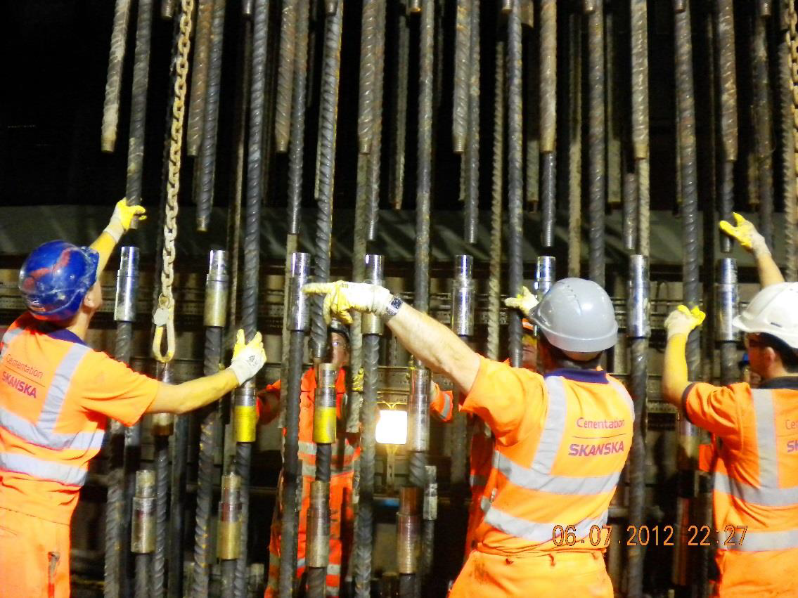
If panels are deep, there are restricted headroom requirements or transport requirements for off-site fabrication dictate multiple cage sections within a panel then the method of cage connection/continuity has to be determined. This can either be spliced or coupled joints or indeed a combination of both. The difficulties of joining cage sections by couplers should not be underestimated – it is both time consuming, frustrating for site teams and more significantly presents a significant safety risk as operatives have to place their hands amongst bars within a suspended load. (See Figure 1) Quick splice systems are available that reduce these risks significantly and are easier and quicker to install and join.

Figure 1. – Site operatives aligning couple cage section.
Particular attention needs to be paid with cage joints when there are multiple layers of main reinforcement. The choice of joint location needs to be selected carefully with respect to bar curtailment positions and also methods of allowing the inner layer of reinforcement to be joined separately from the outer developed.
The requirements for cost effective, stiff structures with minimal section thickness often leads to very high reinforcement densities with large bar diameters in multiple layers being detailed at absolute minimum spacing. It has been well documented for many years (Puller 1996) that this is a significant factor that can have a detrimental effect on the flow of concrete within the panels and hence panel integrity, waterproofness and finish.
There are also limits to what bending radii can be achieved for given bar diameters and even what former sizes are available to create these bends. Pushing these to the limits and the use of certain shapes can lead to inherent potential inaccuracies on bar lengths and positions. This is particularly relevant when considering slab connections and the positioning of couplers within box-outs. The options and benefits of U or L shaped bars with respect to concrete flow should be considered.
Box-outs for slab connections are common place but it should always be remembered that overall they remain a compromise. Their overall benefit to a project to form a structural connections between the walls and slabs without the need for post-drilling bars is clear but as outlined in the Institution of Civil Engineer’s Specification for Piling and Embedded Retaining Walls 2nd Edition (ICE SPERW) they will compromise the flow of concrete and lead to potential inclusions.
As mentioned previously in relation to couplers the provision and joining of sonic logging tubes and inclinometer reservations carries a significant safety risk for site operatives. At Paddington a number of inclinometer installations within the walls were replaced with strain gauge arrays. Looking to the future technology such as thermal integrity profiling should be exploited to obviate the need for handling and joining sonic tubes on site.
Project specifications tend to apply potentially tighter construction tolerances than dictated within the ICE SPERW often in relation to vertical positioning of reinforcement. With deep panels and multiple cage sections it should be considered whether this is realistic as increasing depth and each cage joint will introduce further challenges with regard to achieving ever tighter tolerances.
Particular advantage was gained from using 3D modelling to produce cage detail drawings. This allowed close examination of cage splices and box-outs to check for clashes and buildability in the fixing and cage assembly process. See Figure 2.
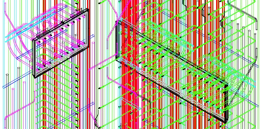
Figure 2. – Sample from 3D CAD model of cages at Paddington showing density of reinforcement and how U-bars for slab connections create a horizontal restriction to the flow of concrete within the panel.
Temporary Works
Various temporary works elements need to be introduced to the reinforcement cages by the contractor. These include longitudinal cage stiffeners to ensure unnecessary cage deflection or damage does not occur during lifting cages in the horizontal position or transitioning them to vertical prior to installation within the panel.
Lifting bands need to be designed and positioned for cage lifting and handling. Trapping bands are required to allow temporary holding of cages over the excavation whilst additional cage sections are added. Finally the top cage section will require a hanging system to allow the cages final position and level to be fixed prior to concreting.
On-Site or Off -Site Fabrication?
As on most infrastructure projects availability of space in city centre sites is sparse, hence opportunities for site fixing of cages is reduced and Crossrail was no different in this respect. Away from the city centre opportunities do exist and Cementation Skanska has experience of both off-site and remote fabrication on the project. Diaphragm walls at Paddington Station, Bond Street Station, Royal Oak Portal and Limmo Peninsular shaft had the reinforcement cages fabricated off site due to space constraints but farther east the portals at Pudding Mill Lane, Plumstead and North Woolwich all had their cages fabricated on-site.
Off-site cage fabrication often becomes a default choice due to the space constraints available at the construction site but, if undertaken by a specialist supplier, also has the advantage of cages being constructed and welded in more controlled factory like environments. To balance these advantages detailing can be more difficult and fabrication has to be much more accurate to allow cages to be joined on site. Even when cages are made in complete coupled lengths and then split the differences in forces between the horizontal factory environment and vertical installation on site means that sections rarely re-align perfectly.
Transport constraints generally limit cage section dimensions to about 18m long and 3.5m wide and there are the obvious additional handling and logistical problems with the potential for damage during transit.
On-site fabrication requires large amounts of space and can require additional lifting details and stiffening requirements but by using lifting/pitching beds increased length cage sections and indeed single piece cages can be constructed. Staggered laps can be used more readily to reduce the reliance on couplers to join cage sections. Cages are generally easier to fabricate and to install within panels.
As well as providing a suitable environment for site welding of reinforcement, an initial challenge to overcome is to gain confidence in site welding and to ensure that adequate supervision and testing is in place along with a stable workforce of qualified and tested welders.
Finally, a key advantage of being able to site fix reinforcement cages is that lines of communication from the construction team to fabrication team are much shorter and therefore improved. Both elements of the operation feel more connected and interdependent and therefore tend to work as a single team helping in regards to safety, quality, production and being able to respond to change.
Rationalisation and Programme Flexibility?
A construction project and programme are rarely completed without the potential for unforeseen problems. Re-sequencing to mitigate programme delay is a frequent possibility. Paddington Station was particularly complex with 165 panels requiring a total of approximately 350 individual cage section drawings that were combined into approximately 60 different arrangements for individual panel types. This degree of individuality to cage types makes for a complex detailing process which then follows for much less flexibility in the construction process on site once committed to a sequence of cage fabrication.
Much thought should be given to minimising the loading cases and minimising and rationalising slab thickness, level changes and voids. Simplification at the design stage can reduce the chances of errors in construction but also liberate flexibility for change as the project progresses. Due thought should also be given to whether additional storage capacity is required to accommodate fabricated cage sections to again give greater flexibility, remove transport delays and ensure that the fabrication facility does not become log jammed.
Health and Safety Considerations
As the Paddington project got underway there were a number of near misses relating to loose bars being found within cages. The presence of tools or temporary bars accidentally being left in cages is not new and can be difficult to manage – particularly with respect to cages pre-fabricated off-site. The risk that these present is that they lie concealed and then fall from the cage when it is pitched from horizontal to the vertical prior to installation in the ground.
Working closely with our specialist supply chain, Cementation Skanska introduced a series of measures that significantly reduced the incidences of loose bars in the cages. (Figure 3)
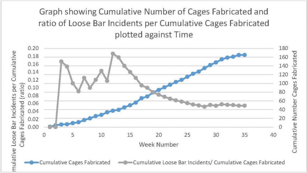
Figure 3. – Graph showing Cumulative Number of Cages Fabricated and Ratio of Loose Bar Incidents per Cumulative Number of Cages Fabricated.
Tools and temporary bars were coloured to make them stand-out from the cages, floors were painted white and lighting improved within the facility to aid checking (Figure 4). The checking regime was improved both in the factory and at site with defined individuals being responsible for signing off cages prior to dispatch and lifting on site.

Figure 4. – Coloured fabrication tools to aid detection during exit checks.
One of the keys to success was improving communications with the fabrication facilities and giving them a better understanding of what happens with the cages once they leave their facilities. Videos of lifting operations were prepared and members of our site team travelled to the fabrication facilities to show how cages were tandem lifted and pitched from a horizontal to vertical orientation. This proved to be a surprise to many of the steel fixers. Site visits were also arranged for key members of the fabrication team.
Conclusions
Extensive use of the diaphragm walling technique in the UK tends to follow with large infrastructure projects (Jubilee Line Extension, Channel Tunnel Rail Link, Crossrail). Shortly after the Jubilee line in the mid-nineties Malcolm Puller wrote about risks of poor concrete as a result of high reinforcement densities. This risk remains and by specifying large bars at minimum spacing these risks should be understood from the outset. Box outs will rarely be perfectly formed due to the restrictions to concrete flow. Indeed, the concrete properties required to maximise flow around bars lead to a higher risk of concrete mix instability and bleed.
Where space is available site fixing reinforcement has many advantages over off-site fabrication. Consideration should be given to rationalising designs to minimise the different numbers of cage types and arrangements. This reduces the chances of mistakes during construction and creates more flexibility for resequencing works.
Safety of the site teams remains paramount. Highly reinforced and coupled cage sections increase the risks of trapping injuries to the site team. Additional measures and checks need to be introduced to minimise the risk of undetected loose bars falling from cages during lifting.
For further details relating to detailing of reinforcement cages for embedded retaining walls the reader is referred to the ‘Specification & standard implementation across Crossrail contracts’ paper also published in these proceedings.
References
Puller M, Deep Excavations: a practical manual, Thomas Telford First Edition 1996.
Institution of Civil Engineers, Specification for Piling and Embedded Retaining Walls, Thomas Telford, 2nd Edition 2007.
-
Authors
