Sub-surface dewatering for an inclined SCL tunnel
Document
type: Technical Paper
Author:
T.O.L Roberts, R. Smith, Dr Alfred Stärk Dipl Ing Dr Ing, W. Zeiszig, ICE Publishing
Publication
Date: 07/09/2015
-
Read the full document
1 Introduction
Crossrail is a major new east-west rail link through central London. The main running tunnels have been driven by TBM with most of the stations and link tunnels constructed using sprayed concrete lining (SCL) techniques.
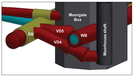
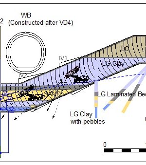
Figure 1 – VD4 tunnel arrangement.
This paper is concerned with the dewatering and depressurisation measures required for VD4 which comprises a 37m long by 6m diameter inclined ventilation tunnel for the Crossrail Liverpool St Station at Moorgate in the City of London. As shown in Figure 1 and 2, VD4 links from the Eastbound Launching Chamber (EB) down below the Westbound Launching Chamber (WB) to an existing shaft. The TBM running tunnels were not constructed at the time of the VD4 works. The shaft was constructed for Crossrail in 2004/5 in the basement of an office development known as Moorhouse. In order to avoid the need to handle potentially large volumes of slurry, the shaft was constructed in ‘dry’ conditions by underpinning. The design and construction of the shaft has been described in some detail in previous publications [1] [2]. The method of shaft construction required depressurisation measures to be adopted to allow excavation through several water bearing horizons including non-cohesive sands (Lambeth Group Laminated Beds and Lower Shelly Beds) present at the level of the connection to VD4. The depressurisation measures required for the shaft construction were successfully achieved using an array of ejector wells installed from surface around the shaft. The wells were operated from the second basement level. The shaft is 8.2m diameter and sufficiently deep (38m below basement level and 50mbgl) that depressurisation wells were also required in the Lower Aquifer (Lambeth Group Upnor Formation and Thanet Sand). Investigations at the start of the VD4 works confirmed that the shaft dewatering wells had been grouted up sometime after the shaft works had been completed.
The purpose of the depressurisation works for VD4 was to reduce pore pressures at the tunnel horizon to zero or below to allow the tunnel to be constructed using SCL techniques.
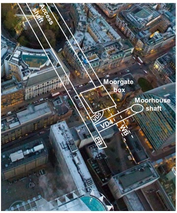
Figure 2 – Aerial view showing location of VD4 below. Pedestrian tunnels and cross passages between the Eastbound and Westbound tunnels beyond Moorgate box not included for clarity. (Photograph courtesy of Crossrail)
1.1 Ground conditions
Information on ground conditions in the vicinity of VD4 was available from a number of sources including:
- Historic boreholes dating from the Moorhouse development.
- More recent boreholes installed as part of the investigations for Crossrail.
- Published records from the construction of the existing Moorhouse shaft.
- Logs of probe holes, piezometer installations and well installations undertaken as part of the Crossrail Liverpool St Station works.
These records have been summarised on the section in Figure 3. This shows that the London Clay (LC) / Lambeth Group (LG) interface is at approximately axis level in the EB tunnel. The top of the Thanet Sand is approximately 7m below invert level for the deepest section of VD4 adjacent to the Moorhouse shaft. It can be seen that the invert for VD4 is entirely in the Lambeth Group with the crown commencing in the London Clay before entering the Lambeth Group.
Figure 3 shows the presence of a channel sand horizon which runs through the inclined invert and axis of VD4. A second water bearing horizon is present at the lowest invert level adjacent to the shaft. The pore pressure profile prior to the start of the works on the new station is given in Figure 4. This is based on monitoring data from approximately twenty piezometers in the vicinity recorded intermittently between 1992 and 2010, and is typical of the prevailing under drained pore pressure profile present in central London.
Over abstraction from the chalk between about 1850 and 1965 has reduced ground water levels in the Lower Aquifer below London comprising the Lambeth Group Upnor Formation, Thanet Sand and Chalk. Groundwater levels had started to rise between 1965 and 1990 but are now maintained by pumping from wells across London to protect the extensive deep infrastructure which was constructed after groundwater levels had been lowered [3]. Groundwater levels in the Terrace Gravels (Upper Aquifer) above the London Clay are largely unchanged. The London Clay and Lambeth Group clays act as a dividing layer between the Upper and Lower Aquifers. Figure 4 shows that the non-cohesive sand and gravel horizons which are intermittently present, mainly in the upper Lambeth Group, have not been fully drained and form an Intermediate Aquifer. The Crossrail site investigation works have shown that the Mid-Lambeth Hiatus (MLH) is the approximate boundary with any non-cohesive horizons below this level generally reflecting groundwater levels in the Lower Aquifer whilst those above can exhibit elevated pore pressure between those in the Upper and Lower Aquifer.
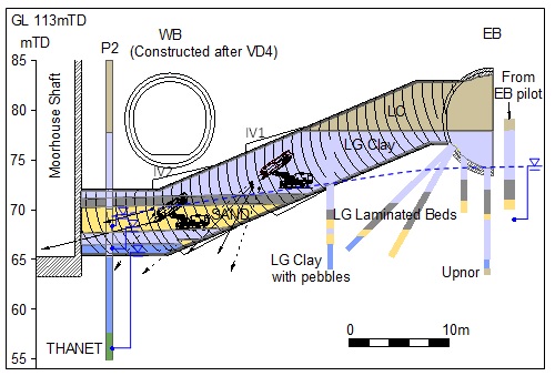
Figure 3 – Long section of VD4 showing ground profile.
The precise explanation as to why elevated pore pressures persist in the Upper Lambeth Group is not immediately clear. It is a common misconception that the elevated pore pressures in the Lambeth Group are relic and once dissipated will not recover. This may be partly true in so far as the highest pressures, those above 100 to 150kPa, have proved elusive to reproducible measurement. Pressures below this do tend to recover, at least partially, when pumping stops. Whilst the vertical permeability of the lower Lambeth Group clays is clearly very low (probably <10-9 m/s) it seems highly unlikely that elevated relic pore pressures could be sustained over more than 100 years without some form of seepage inflow which exceeds the downward leakage outflow. Possible sources of seepage inflow to the Upper Lambeth Group sands include:
- Leakage from the London Clay. The London Clay has a similarly low permeability to the Lambeth Group clays and is significantly thicker. The lowered pore pressure noted in the London Clay on Figure 4 suggests this may provide some contribution.
- Leakage via natural fissures or scour features in the London Clay. Seepage flows are occasionally evident in sand laminations or Limestone bands towards the base of the London Clay. Scour features which penetrate through the London Clay do exist but are relatively rare.
- Seepage from the upper aquifer via un-grouted or poorly grouted boreholes. There are many site investigation boreholes and redundant wells across London but little factual evidence that these provide a significant flow path through the London Clay.
- Horizontal seepage from areas where the Lower Aquifer groundwater levels are above the Mid-Lambeth Hiatus. This could be a factor but the distances involved are several kilometres.
All of the above may have a part to play but their relative significance remains unclear.
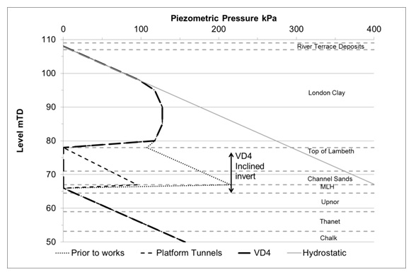
Figure 4 – Pore pressure profile.
1.2 Experience from station tunnels
Access from ground level to the VD4 works was via a temporary shaft in Finsbury Circus and the largely complete station tunnels and pedestrian tunnels. For the most part excavation and SCL primary lining of these had been completed with secondary lining works about to commence. The crown of the station tunnels is in London Clay with Lambeth Group soils, with the potential for water bearing sand horizons, present from approximately axis level.
The station tunnels were constructed in a sequence comprising an SCL pilot tunnel driven full length followed by an enlargement with top heading, bench and invert. An assessment of the SCL works based on the highest credible pore pressures recorded indicated that the required clay cover below invert was approximately 3m for the pilot tunnel and 4m for the enlargement. A careful review of the lithology of the Lambeth Group confirmed that sand horizons were generally sufficiently low that the vast majority of the platform pilot tunnel works could be constructed without the need for active depressurisation.
The depressurisation strategy adopted for the station tunnels was regular overlapping forward inclined auger probe drilling in the advancing face of the pilot tunnel. Vertical probe drilling was then undertaken from the completed pilot tunnel to confirm conditions for the enlargement. Where water bearing channel sands were encountered, the probe holes were then completed as wellpoints and connected to a vacuum dewatering pump. The effectiveness of these measures was monitored by using un-pumped wellpoints as standpipe piezometers. It proved impossible to preserve wellpoints installed in the pilot tunnel through the enlargement sequence. This strategy was generally satisfactory other than the occasional need to re-install wellpoints lost in the course of the enlargement works. This was particularly the case where sand horizons were present above the invert of the enlargement. The proximity of the station tunnels sometimes allowed wellpoints to be installed from a completed tunnel to depressurise an adjacent tunnel under construction. Also, where it was necessary to operate a wellpoint system in a blind pilot tunnel, it was sometimes feasible to install a service connection for power and discharge to avoid passing these services through the advancing enlargement face.
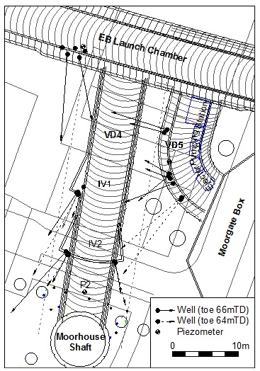
Figure 5 – Plan of installed depressurisation arrangements.
1.3 Access constraints
VD4 is located in the heart of one of the busiest cities in the world and it was immediately apparent that constraints on access would be the primary driver for the depressurisation strategy. Access to the Moorhouse shaft was now in the basement of an occupied office building. In due course improved access from the surface to the basement would be available to allow secondary lining and fit out of the shaft but this was for a separate contract later in the program. In any case headroom in the completed basement was insufficient to reinstate the surface wells around the shaft. The remainder of VD4 was directly below existing occupied buildings or the congested construction site for the adjacent Moorgate Box ticket hall.
Access from the Moorgate Box was not available as it was under construction. Access from the WB SCL launch chamber immediately above VD4 was not available as it had not yet been built. The only remaining available options for installation of depressurisation wells were from the EB tunnel, from the adjacent VD5 tunnel and from the face of VD4.
2 Depressurisation strategy
The central 28m section of VD4 slopes down at an angle of 23o from the horizontal. This is too steep for conventional excavation plant to work safely and the lack of useable access to Moorhouse shaft meant a down slope excavation sequence, using an excavator adapted for the purpose, was required. The in-tunnel wellpoint strategy for the station tunnels had been successful, however it was apparent that the access constraints, geometry and alignment of VD4 plus the expected geology required a modified approach.
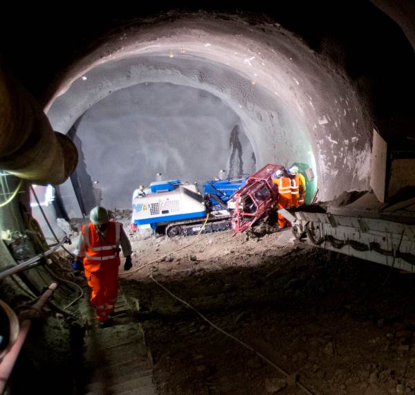
Figure 6 – Photograph of rig set-up at second intervention.
Depressurisation of the first part of VD4 could be achieved using wells installed from the adjacent VD5 tunnel and the end of the EB tunnel. Installation level for these wells was approximately 76mTD (0mOD = 100mTD); over 10m above the lowest invert level for VD4. The required suction was then too great for wellpoint pumps, requiring resort to an ejector scheme. The ejector pumps and recirculating tanks could usefully be accommodated in VD5 without hindering access to VD4, see Figure 5.
One of the piezometers (P2 on Figure 5) installed for the Moorhouse shaft works remained accessible and was recommissioned. The installation comprised a standpipe with response zone at 63.5 to 64.5mTD (at VD4 invert) and two vibrating wire transducers with response zones at 68 to 69mTD (within the Lambeth Group sand channel) and at 56.5mTD (in the Thanet Sand). Monitoring data from this confirmed the pore pressure profile shown in Figure 4. A 24 hour pumping test was conducted on wellpoints installed for the EB Tunnel works at the entrance to VD4. This resulted in a response of just 0.2m in the sand channel at P2 indicating some hydraulic connection but also confirming that pumping in this area would be unlikely to achieve the drawdown required as VD4 approached the shaft. In order to address this two intervention locations (IV1 and IV2, see Figures 3 and 5) were identified for in-tunnel ejector well installation. The face was enlarged at each intervention so that the wells could be drilled inclined down and forward but would not then need to be broken out for the subsequent advance. Pipework was run down the side of VD4 connecting the ejector wells back to the pumping station in VD5. The final well array installed is shown in Figure 5. The planned well array comprised 30 ejector wells; 26 targeting the sand channel on each side of VD4 at 3 m spacing with 4 targeting the lower water bearing horizon present at invert. This was reduced to 15 No. ejector wells plus 6 targeting the lower horizon based on feedback from the monitoring and face logs from the tunnelling. The SCL enlargement at the second intervention and drill rig set up are shown in Figure 6.
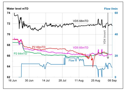
Figure 7 – Selected monitoring results.
3 Monitoring results
Monitoring data from the piezometers installed in VD5 and from P2 is given in Figure 7. Also shown is the discharge flow rate from the ejector system. The upper piezometer in VD5 recorded a significantly higher pore pressure throughout. This piezometer did respond to pumping; see for example the two up spikes in late August when pumping was briefly interrupted due to power outages. No significant seepage flows were encountered during excavation of VD4 suggesting that the high level sand horizons in the vicinity of VD5 and the EB tunnel are not directly connected to the main sand channel in the vicinity of the Moorhouse shaft.
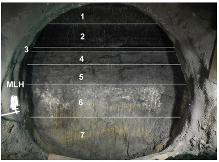
Figure 8 – Photograph of VD4 face 4 m from Moorhouse shaft.
Piezometer P2 69mTD indicated that a vacuum had developed in the sand channel when pumping commenced. This increased when additional ejector wells were installed at the first intervention at the end of July. The additional wells installed at the second intervention did not further improve the drawdown. The piezometers in the lower water bearing horizons were just above invert level which led to a decision to increase the number of wells targeting this horizon.
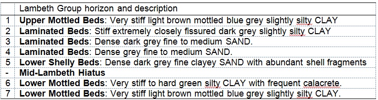
Table 1 – Face log of Figure 8.
The face exposures during the SCL advances gave an excellent opportunity to assess the ground conditions and log the face. The information was used to continuously refresh and update the ground model. An example of the logging of the face exposure is given in Figure 8 and Table 1.
4 Conclusions
The complex stratification and intermittent nature of non-cohesive horizons makes depressurisation of the Lambeth Group often less than straightforward. This was further complicated at VD4 by restricted access and awkward geometry which led to the decision to use an inclined in-tunnel ejector well dewatering system. This allowed maximum use of the limited access available and also allowed the option of close well spacing along both sides of the alignment with just two interventions.
References
[1] McNamara, A.M. Roberts, T.O.L. Morrison P.R.J. & Holmes, G. 2008. Construction of a deep shaft for Crossrail, Proceedings of the Institution of Civil Engineers, Geotechnical Engineering 161, 299–309.
[2] Morrison P.R.J. McNamara, A.M. & Roberts, T.O.L. 2004. Design and construction of a deep shaft for Crossrail, Proceedings of the Institution of Civil Engineers, Geotechnical Engineering 157, 173–182.
[3] Environment Agency. 2014. Management of the London Basin Chalk Aquifer: Status Report, Environment Agency, London.
-
Authors

T.O.L Roberts
WJ Groundwater Ltd
R. Smith
WJ Groundwater Ltd

Dr Alfred Stärk Dipl Ing Dr Ing - BeMo Tunnelling
Dr Alfred Stärk is Chief Geotechnical Engineer and Engineering Manager at BBMV for Crossrail Contract 510 ‘Whitechapel and Liverpool Street Station Tunnels’ since March of 2011. He started his career at the University of Hanover, Germany, where he worked as assistant professor and consultant for 10 years. In 2002 he joined BeMo Tunnelling, Innsbruck, Austria. He now has 25 years of experience in large-scale tunnelling, mainly with sprayed concrete lining in soft ground.
W. Zeiszig
BeMo Tunnelling
