System Integration EMI Issues in Large Complex Installations – A Case Study
Document
type: Technical Paper
Author:
Jimmy James BEng(Hons) MSc CEng MIET MIEEE
Publication
Date: 02/12/2021
-
Read the full document
Introduction and Industry Context
Large infrastructure projects such as Crossrail present significant challenges in managing Electromagnetic Compatibility (EMC) through the design, installation and commissioning stages of the project.
Main Story
During the commissioning of the lighting control system at a ventilation shaft the lighting control contractor found they could not communicate with many of the lighting devices on the system. After going through their usual trouble shooting routine they could find nothing wrong with their system. It was noted that the Tunnel Ventilation System (TVS) was operational due to the proximity to the variable speed drive (VSD) room and they could be heard operating. Further investigation confirmed that it was the TVS system that was causing Electromagnetic Interference (EMI) with the lighting control system.
The lighting control used was a Digital Addressable Lighting Interface (DALI) system. The DALI bus used to control the lighting devices is a two wire system with a nominal 16 V dc that is current limited to 250 mA. This allows small devices such as light switches and presence detectors to be directly powered from the DALI bus. Data is transferred on the bus at a rate of 1200 bit/s and the recommended maximum length of the DALI bus is 300 m in order to limit the voltage drop to an acceptable level.
When the EMC investigation started the first observations made were that the DALI bus wires ran with the low voltage (LV) mains wiring in the trunking and conduits and that the wires for both the LV mains and the DALI bus were ‘singles’ and hence had absolutely no good EMC properties. The DALI contractor stated that this was standard in their industry to wire the DALI system like this.
The Crossrail project required all the stations, shafts and portals contractors to engage the services of an EMC Consultant and to produce an EMC Control Plan for the site. In line with good EMC practices the EMC Control Plans state that power cables should be segregated and separated from other services. Although it is industry standard practice to run the DALI bus wires with the LV mains cables this is in contravention to the Control Plan’s guidelines and no contractor or EMC Consultant raised this as a potential issue or carried out an EMC assessment. This highlights that blind spots do exist among EMC specialist concerning certain systems as none of the EMC Engineers working on Crossrail were aware that DALI bus wires ran in the same containment as LV mains cabling.
Both the lighting control contractor and the TVS contractor claimed their equipment met applicable standards which was correct. However, even experienced EMC specialist seems unaware that certain EMC standards allow some products to produce very large amounts of conducted emissions. Figure 1 shows conducted emission quasi-peak limits used by various EMC standards (average limits are not shown to aid clarity). Table 1 cross references typical standards used in railway projects with the limits shown in Figure 1.
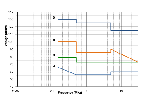
Figure 1. Conducted emission quasi-peak limits used in various EMC standards
Standard
Limit Line A B C D No limit EN 61000-6-3 Y – – – – EN 61000-6-4 – Y – – – EN 61800-3 C1 C2 C3 (<100 A) C3 (>100 A) C4 EN 62040-2 C1 C2 C3 (<100 A) C3 (>100 A) C4 EN 12015 – <25 A 25 – 100 A >100 A – Table 1. Conducted emissions limits used by common standards used in railway projects. See Figure 1 for limit line
Limit line D is used by the VSD standard EN 61800-3[1] category C3 (>100 A), the UPS standard EN 62040-2[2]category C3 (>100 A) and by lifts and escalator standard EN 12015[3] for equipment rated >100 A. Limit line D is 130 dBµV between 150 kHz and 500 kHz. This is 3 V measured in a 9 kHz bandwidth and is comparable to the 3 V conducted RF immunity limit used by the residential, commercial and light industrial (RCLI) standard EN 61000-6-1[4]. In other words there is no margin between the conducted emission limit and the immunity level.
It is also worth noting that the VSD standard EN 61800-3[1] and the UPS standard EN 62040-2[2] has an equipment category C4. There is effectively no conducted emission limit for these devices and, from an EMC perspective, extreme caution should be taken in using this category of equipment.
Figure 1 starts at 9 kHz but the emissions limits start at 150 kHz so there is no limits on the levels of emission between 9 kHz and 150 kHz. For power electronic equipment such as VSDs their peak emissions occurs below 150 kHz where there are no limits.
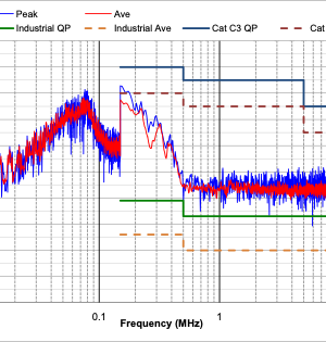
Figure 2 shows EMI measurements were made on the LV mains supply between phase and earth using a high voltage probe according to EN 55016-1-2[8]. The frequency range between 9 kHz and 30 MHz was measured. Between 9 kHz and 150 kHz a measurement bandwidth of 200 Hz was used and between 150 kHz and 30 MHz a bandwidth of 9 kHz was used in accordance with EN 55016-1-1[7]. This change in measurement bandwidth at 150 kHz is why the measure EMI changes level at 150 kHz. The noise floor is high due to the external attenuation added to the spectrum analyser to ensure it was not overloaded. From Figure 2 it can be seen that peak emissions occurs around 80 kHz with significant emissions present up to approximately 500 kHz before it rapidly decreases. The key point to take from this is that peak emissions can occur in the frequency range where there are no limits.
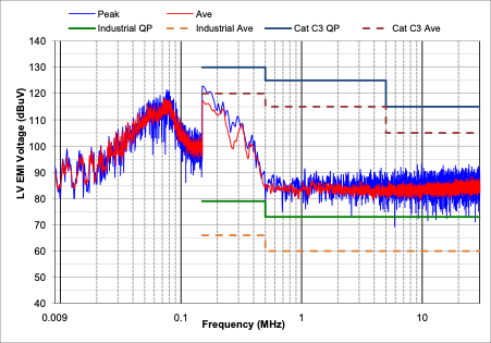
Figure 2. Measured EMI on LV mains supply with TVS VSD operating
In common with many railway projects Crossrail used a zoned approach to defining the immunity requirements of equipment. Zones are defined as being a certain distance from the centreline of the nearest track and equipment installed in zones closer to the track require higher immunity levels. This approach works well for radiated EMI from the railway itself but as the LV mains supply is common throughout the installation and covers all zones it does not adequately address high levels of conducted emissions from equipment connected to the common LV supply.
This EMI issue was only notice because the lighting control contractor was trying to commission their equipment while the TVS was active. When the DALI system loses communication between the controller and the lights the light come on at 100% brightness as a safety feature so it is not obvious that there is an problem and all other sites claimed they had no issues. The contractor of the site where the issue was found was also responsible for another site with TVS installed and carried out a survey at that site which also uncovered the EMI issue. At this point Crossrail instructed all remaining sites with TVS to carry out a specific integration teste between TVS and the DALI systems. Most of these sites showed that, when looked for, these were EMI issues.
The TVS VSDs used on Crossrail where rated as EN 61000-3[1] category C3 drives. They ranged in size from 185 kW to 450 kW and hence all required greater than 100 A supply current. These drives produced high levels of common mode EMI onto the LV mains supply as shown in Figure 2 and this was capacitively coupling to the DALI bus wires that shared the same trunking and conduit. The DALI system used was unbalanced about earth due to the use of singles and the control module also connected one of the DALI bus wires to earth. This unbalance about earth makes the system susceptible to capacitive coupling.
Figure 3 shows the voltage across the DALI buswires with the TVS off and Figure 4 shows the voltage with the TVS on.
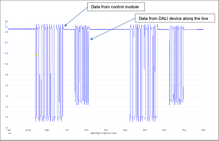
Figure 3. Voltage across the DALI buswires with the TVS off
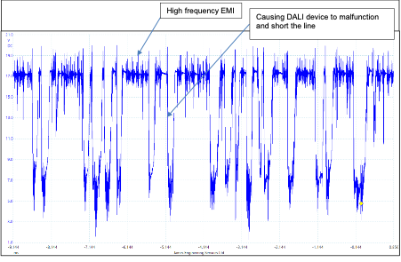
Figure 4: Voltage across the DALI buswires with the TVS on
Mitigations used involved either running the DALI buswires in a separate conduit or filtering the LV supply that ran with the affect DALI lines. This was archived by fitting filters to the relevant distribution board.
Filtering the VSDs themselves was considered but the VSD manufacture would not support this as they were concerned that filters on the VSDs would increase the common current flowing through the VSD which could drive the internal chokes into saturation and also increase the common mode voltage seen that the terminals on the fan motors.
Lessons learned
It is only natural that individual contractors concentrate on their scope or work which is why it is important for a system level view to be adopted. EMC should be specifically considered during the interface workshops held between different contractors.
All loads whose emissions exceed those given in the generic industrial emission standard EN 61000-6-4[6] should be identified and relevant stakeholders notified. It is also important to consider emission below 150 kHz as these are not adequately addressed by product or generic emissions standards. Sources of high level conducted emissions needs to be understood early in the design stage to minimise any impact later in the project.
Programme in reviews throughout the design stage and installation stage to ensure the EMC guidelines in the EMC Control Plans are followed. For any deviation from the guidelines perform an EMC assessment to determine if there will be an unacceptable impact. Identify each interface that a piece of equipment or system uses and understand the type of cable used and where it is runs with respect to other cables. A simple form or checklist could be produced to aid this process.
Ensure specific integration tests between any systems with high levels of emissions and potential victim system are planned into the integration testing stage.
Conclusion
Large multi-discipline infrastructure projects can be challenging to ensure EMC is achieved. It’s important that any high emissions sources are identified early and all stakeholders notified. It is essential that EMC specialist are aware that certain EMC standards allow very large levels of conducted emission to be exported onto the power supply and to ensure all other load connected to that supply are compatible.
EMC reviews during the design and installation stages are required to ensure EMC design guidelines are being followed and any deviations undergo an EMC assessment. Integration tests between high emissions loads and potential victim systems needs to be planned into the integration testing stage.
References
[1] EN 61800-3:2004 Adjustable speed electrical power drive systems Part 3: EMC requirements and specific test methods
[2] EN 62040-2:2006 Uninterruptible power systems (UPS) Part 2: Electromagnetic compatibility (EMC) requirements
[3] EN 12015:2015 Electromagnetic compatibility – Product family standard for lifts, escalators and moving walks – Emission
[4] EN 61000-6-1:2007 Electromagnetic compatibility (EMC) – Part 6-1: Generic standards – Immunity for residential, commercial and light-industrial environments
[5] EN 61000-6-3:2007 Electromagnetic compatibility (EMC) – Part 6-3: Generic standards – Emission standard for residential, commercial
[6] EN 61000-6-4:2007 Electromagnetic compatibility (EMC) – Part 6-4: Generic standards – Emission standard for industrial environments
[7] EN 55016-1-1:2007+A2 Specification for radio disturbance and immunity measuring apparatus and methods – Part 1-1: Radio disturbance and immunity measuring apparatus – Measuring apparatus
[8] EN 55016-1-2:2014 Specification for radio disturbance and immunity measuring apparatus and methods – Part 1-2: Radio disturbance and immunity measuring apparatus – Coupling devices for conducted disturbance measurements
-
Authors

Jimmy James BEng(Hons) MSc CEng MIET MIEEE
Jimmy is a Chartered Engineer with over 25 years’ experience as a technical specialist in Electromagnetic Compatibility (EMC).
He has been with the Crossrail project in the CRL Chief Engineers Group since 2017, managing the delivery of EMC on the project.