The Benefits of a CEPS (Centralised Emergency Power Supply) System for a Modern Metro
Document
type: Technical Paper
Author:
Neville Leary FIET
-
Read the full document
Executive summary
The purpose of this paper is to demonstrate savings in cost & programme, with regard to both CAPEX (Capital Expenditure) and OPEX (Operational Expenditure) that can be achieved within new Metros in London if a connection to the LUL (London Underground Limited) HV (High Voltage) network can be agreed. By connecting to the 22kV network, it is possible to receive a CEPS connection. The benefits to a future railway include:
- Reduction in UPS autonomy from 3 or 4 hours to just 1 hour
- Reduction in the quantity of batteries required
- Reduced battery room size
- Reduction in the HVAC (Heating, Ventilation & Air Conditioning) system that cools & ventilates the batteries
- Reduction in mechanical plant & plant room
- Reduction in the electricity costs of running the mechanical plant
- Reduction in mechanical plant maintenance time & costs
- Reduction in battery replacement costs
- Reduction in battery recharge times (from circa 10 hours to 3-4 hours based on Valve Regulated Lead Acid (VRLA) batteries)
Apart from these savings and reductions in space requirements, the LV (Low Voltage) switchboards do require additional equipment. When operating from CEPS, only safety critical loads can be connected. As such, load shedding of all other circuits is required.
Despite this, the recommendation of this report will state that if traditional UPS systems are to be employed on future rail projects in London, then the benefits of introducing a CEPS connection together with the load shedding at the LV switchboards will result in savings of CAPEX, OPEX and space.
Kings Cross station fire, 18th November 1987
Despite a no smoking ban introduced by London Transport in 1985, this ban was not adequately enforced and was a primary contributor to the incident which occurred at Kings Cross station which cost the lives of 31 people.
The cause was investigated by Desmond Fennell OBE, QC and his team of specialist investigators with the report into his findings being published and presented to Parliament in October 1988.
Over the following years, recommendations in the Fennell Report were implemented across the London Underground network. This was a significant amount of work requiring an army of engineering staff to implement the agreed solutions which included robust emergency lighting, radio systems that were common to that used by the emergency services and robust power supplies.
Ultimately, the Fennell Report paved the way for the introduction of The Fire Precautions (Sub-surface Railway Stations) Regulations 1989 (the 1989 Regulations). In response to this, London Underground’s Chief Engineers Group created a suite of Category (CAT) 1 standards covering all disciplines. Compliance with these standards would ensure compliance with the aforementioned regulations.
The Fire Precautions (Sub-surface Railway Stations) Regulations 2009
The 1989 Regulations were subsequently updated and reissued in 2009 as the Fire Precautions (Sub-surface Railway Stations) Regulations 2009 (the 2009 Regulations), and maintain the requirement on the operator to ensure the safe evacuation of their customers. Systems made available to achieve this include:
- Public Address (Station staff must be able to communicate with their customers)
- CCTV (Closed Circuit Television) (Station staff must be able to see their customers)
- Station radio (Station staff must be able to communicate with each other)
- Fire detection system (includes its own monitored dedicated battery backup)
- Lighting (to ensure everybody can see their way to the exits)
Operation of these systems must continue during, for example, a fire or a power cut. When exposed to a fire, it is expected that power cables and their support system will continue to function for at least 120 minutes. Not only must they function, but the high-tech materials used in the manufacture of the cables must not drip flaming droplets onto the ground (or fire fighting personnel) below. Noncritical power & control cables must be manufactured from low smoke zero halogen (LSOH) materials to eliminate the production of toxic smoke.
Autonomy of the above listed systems will include the requirement not just to facilitate the safe evacuation of a station, but also all passengers stranded on trains stuck in tunnels between stations.
BS EN 50172 & BS5266 Emergency escape lighting systems, LUL CAT 1 standard 1-066 Lighting of London Underground Assets
Provision of adequate emergency lighting
There are several British Standards documents that address the requirements for lighting station premises. Specifically, for emergency lighting on an underground railway station, compliance with the suite of LUL CAT 1 standards will ensure compliance with the various BS documents, including the 2009 Regulations.
Emergency lighting illuminates areas that lead occupants to the nearest fire exit. In an outage, the lights should remain on for three hours. A requirement of the above British Standards, this ensures that all occupants of the station and trains can safely make their way to the exit and attending emergency services can access the building safely if required.
For an underground railway station, the three hours exceeds the time it may take to de-train passengers from a tunnel, including the time taken for the emergency services to reach the train.
Regarding the above two sets of requirements, there are several ways in which these have been met on the existing LUL network, and these are:
- Central UPS systems (existing Crossrail solution incorporating four units per station split east and West with loads split between telecommunications, and General)
- Standby generators & local Off-line Battery Invertor (OLBI) (the CEPS system used across London Underground)
To comply with their legal requirements, solutions for the Elizabeth Line have been developed to exceed the current requirements set out by the above regulations & standards.
All cables and wiring on the project are LSOH. All safety critical wiring is 2-hour fire survivable, as is the cable management system that supports it. Dual power supplies (A+B) are fire segregated. All safety critical loads are supplied from sizeable UPS systems, with local Emergency Distribution Boards (DBs) fire segregated from normal supplied A+B DBs.
As far as reasonably practical, the cable routes throughout the sub-surface railway are segregated by distance.
Switchrooms for the A+B equipment are segregated from each other in fire rated rooms. Incoming HV A+B supply cables use separate fire protected routes throughout their length. HV-A switchboard is in a separate fire rated room to HV-B switchboard. HV A+B step down transformers are also fire segregated and all rooms where cables pass from one to another are interconnected with fire stopped cable routes.
Back up power supplies for safety critical systems are afforded by sizeable UPS systems. The General UPS supplies lighting, and other small critical loads. The telecommunications UPS supplies all telecommunications loads across the station. Due to the size of Elizabeth Line stations, the latter is duplicated within both the East & West ticket halls. All UPS equipment is located in fire rated rooms. All Plant rooms have dedicated fixed fire detection systems, and all equipment to be used on the project passes through a robust materials compliance process prior to being accepted for use.
The UPS systems employed have been sized to meet the requirements and demands of the Project Chief Engineer, expectations of which are outlined within Materials & Workmanship specification JV32 as follows:
-
- Emergency Lighting autonomy 3 hours.
- Communications autonomy 4 hours.
Note 1: The provision of 24 hours autonomy for the PAVA system in quiescent mode followed by 30 minutes load is being provided within the equipment by the C660 telecommunications contractor.
Note 2: Mechanical plant loads shall not be connected to either the Emergency Lighting or Communications UPS.
Note 3: The connection of UPS supplies for the OHLE tripping supply and tunnel ventilation damper controls to the UPS units shall be fed from the Emergency Lighting UPS.
c). The Emergency Lighting UPS shall operate in on-line mode. The Communication UPS shall be a single on line, double conversion type, continually providing conditioned power to the loads and shall be connected such that it is powered from the normal mains when both A&B supplies are present and only transferring to UPS when both A&B supplies have failed.
d). Each UPS system shall be complete with an input rectifier, batteries, inverter, internal by-pass and static switch. An independent external bypass, and an external switchboard shall also be included as part of the UPS installation. The UPS shall provide galvanic separation between input and output under all conditions, if separate supplies are provided at the Rectifier and internal static bypass.
e). The UPS shall be located in a dedicated Emergency Switchroom (ESR) room, with the batteries located remotely in a separate room.
f). The UPS systems shall be in accordance with Network Rail, Product Specification for UPS Ref: NR/ PS/ ELP/ 00007 for Signalling Applications in service conditions defined in Clause 4.11.1 c) except where specifically stated otherwise in this Specification.
g). The UPS battery charge system shall be capable of recharging a fully discharged battery to 80% fully charged within 8 hours and to 95% capacity in a further 12 hours. Note: this requirement replaces that contained in NR/ PS/ ELP/ 00007 Clause 4.9.3.
h). The UPS battery and charging system for the emergency lighting shall also be designed so that on a partial discharge test of 20% load for 1 hour, the battery shall have the required 3 hour autonomy after 3 hours recharge.
i). The UPS inverters & batteries shall be sized accordingly to ensure adequate fault current is generated (after autonomy of batteries is exceeded) to trip the down-stream protective devices.
j). UPS protection model to be prepared to demonstrate all faults can be cleared within maximum disconnection times.
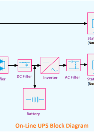
It is noted that the UPS systems employed are required to be “on-line”, whereas similar systems used on London Underground stations are “off-line”. The off-line UPS feeds its load via the bypass circuit, whereas the on-line feeds its load via the rectifier circuitry. The benefit of the on-line UPS is the load receives a filtered supply and when there is a loss of the AC mains supply, the load continues to operate without being affected.
With the off-line UPS, the load receives unfiltered mains electricity, and when there is a loss of the AC mains, the load may experience a momentary loss of supply. This is best explained by the following sketches.
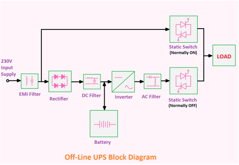 Figure 1. Off-line UPS
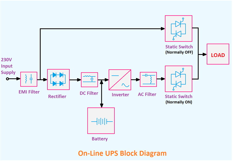 Figure 2. On-line UPS
As required of JV32, The UPS systems procured for The Elizabeth Line are the on-line type, but also benefit from having internal & maintenance bypass capability. This will enable the maintenance technicians to take the UPS out of service for certain maintenance tasks during the engineering shift without impacting station non-operational hours activities. The arrangement used for the Elizabeth Line is identified within the following sketch.
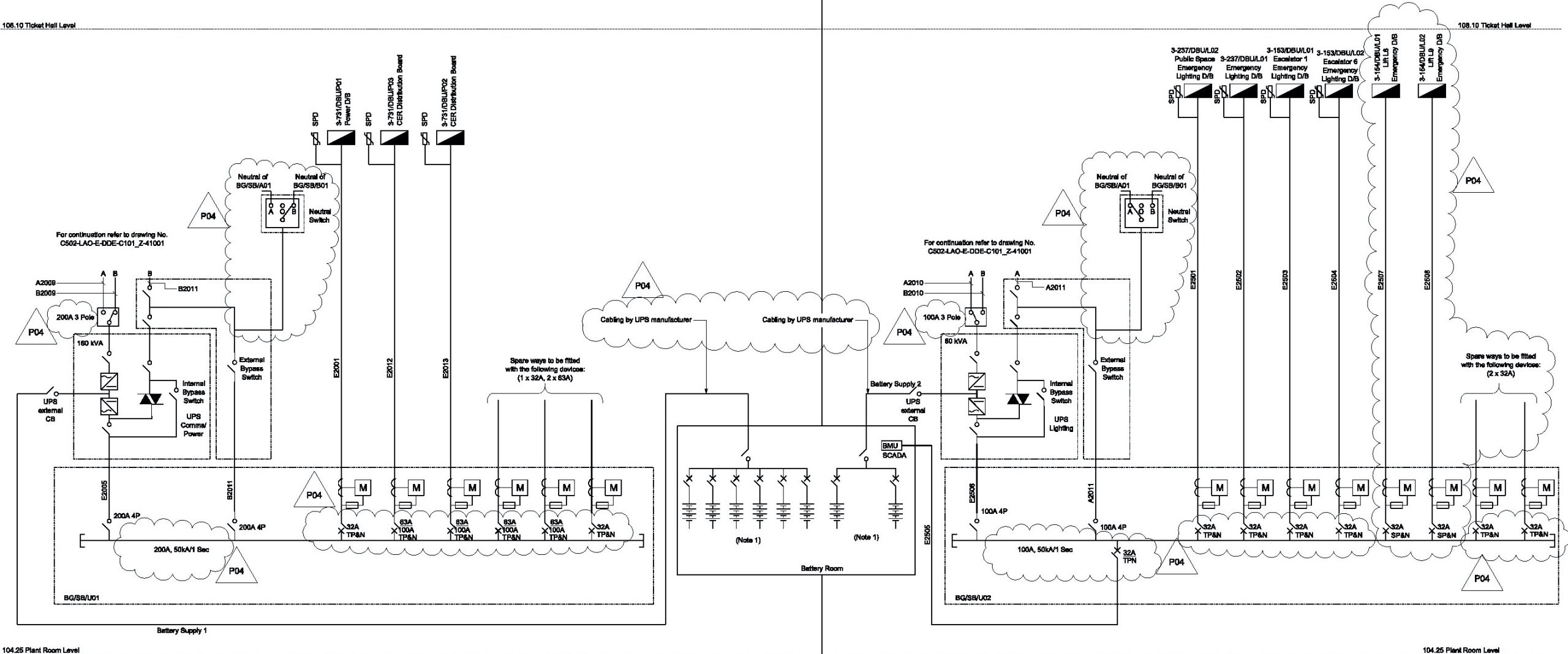 Figure 3. UPS arrangements at a Typical Elizabeth Line station
Figure 3 shows the dual UPS systems at the east ticket hall at Liverpool Street station. The UPS systems are located in a communal emergency switchroom along with the two output 800A Form 4 type 2 LV sub-switchboards.
The rectifier or charging circuit of each UPS is fed via A+B fire rated Steel Wire Armoured (SWA) cables run on diverse routes via a local 400A Auto Transfer Switch (ATS). The static switch within the UPS is fed from the external bypass which also has the capability via a pair of Castell Interlocks to feed directly onto the output LV Sub-switchboard, enabling the UPS to be taken out of service.
Typical size of each UPS at a large station is 200kVA. Across the project, there are 60 UPS systems of varying sizes providing approximately 6MVA of battery backup energy. This equates to the following:
- Typically, a 100kVA UPS can weigh up to 1,500kg with a further 2,000kg for the batteries.
- Collectively this means there are in excess of 120,000kg of batteries
- Batteries require replacement every ten years.
- Battery rooms need to be kept at 21⁰C max
- Size and cost of procuring the mechanical plant to be considered
- Cost of running & maintaining the mechanical plant to be considered
- Space for mechanical plant to be considered
- All cable runs include provision for LV-A, LV-B and UPS cable routes.
- Loads supplied from a central UPS must be fed using 120-minute fire survivable cables and cable management
Whilst the UPS solution provided for the Elizabeth Line complies with all applicable legislation, future rail projects in London must consider alternatives that would save on CAPEX, OPEX, & space within the sub-surface environment.
London Underground CEPS system
When the Metropolitan Railway Company decided that running steam trains in tunnels was no longer acceptable, trains powered by electricity were introduced. At the time, electrical generation in London did not have spare capacity to run the railway. This prompted the railway operators to build their own. This saw new coal fired power stations being built to serve the individual railways at Neasden, Lots Road, Wood Lane, Stockwell and Greenwich. Today all but Greenwich have been decommissioned, demolished, or if of special interest, re-developed.
Greenwich is where the CEPS generators are located. Powered by gas turbines, there are always three machines on standby each capable of delivering 11MW (33MW total) of energy to the LUL HV network.
All LUL sub-surface stations have suitably sized Off-line Battery Invertors (OLBI) with autonomy of just 1 hour. In the event of a mains failure, the OLBI takes over the operation of all safety critical systems on the station. In parallel, the machines at Greenwich are started, synchronised and after 20 minutes or so are brought on-line. Equipment at the stations will already have load shedding capability on the non-essential systems, leaving the CEPS supply to take over from the OLBIs. On restoration of the main supplies, the CEPS system is shut down and returned to standby. OLBIs return to their original state and the stations re-open once the OLBI batteries have achieved a predetermined level of charge.
The CEPS supply enters an existing London Underground station via the LUL HV cable. It is important to understand that CEPS is not provided to run the railway, but to facilitate evacuation when there has been a power cut, or other significant emergency, so the generators are sized to only supply power to the safety critical loads.
To ensure only emergency critical loads are connected to the CEPS supply, automatic load shedding was required. The London Underground LV Switchboards were built to facilitate this requirement. As a result of the introduction of the 1989 Regulations LUL were required to retrofit their existing stations with the OLBIs, and it is worthy of note that space to facilitate this installation at every sub-surface station across the LUL network was at a premium. Issues to overcome were:
- Cost of maintaining the CEPS generator station
- Sub-surface stations to accommodate OLBI system with 1-hour autonomy
- Output loads to be fed using 2-hour fire survivable cables and CMS (cable management systems)
- Load shedding required to remove non safety critical loads when on CEPS
Outcome
- Cost of CEPS upkeep is shared across every user
- Spaces identified within existing station footprint to accommodate the 1-hour OLBIs.
- Future cost saving in the quantity of batteries to be replaced every ten years
- Reduced size of mechanical cooling plant & plant room space
- LV switchboards replaced with built in load shedding
- All safety critical loads resupplied with 2-hour fire survivable cable and CMS
Crossrail power supply arrangement
Crossrail central section has two separate HV networks. The east side, from Limmo Peninsula to Plumstead is fed at 11kV. To facilitate tunnel construction, two 11kV supplies were procured from UKPN at Plumstead and two at Limmo, and these were used by the tunnel boring machines. On completion of tunnel construction, these four supplies were recycled and became the permanent non-traction supplies for that area of the project. HV-A runs alongside the eastbound tracks/tunnels whilst HV-B runs alongside the westbound tracks/tunnels. For operational purposes, and to facilitate maintenance, Open points are located at North Woolwich Portal. HV bus couplers are located at both Limmo & Plumstead.
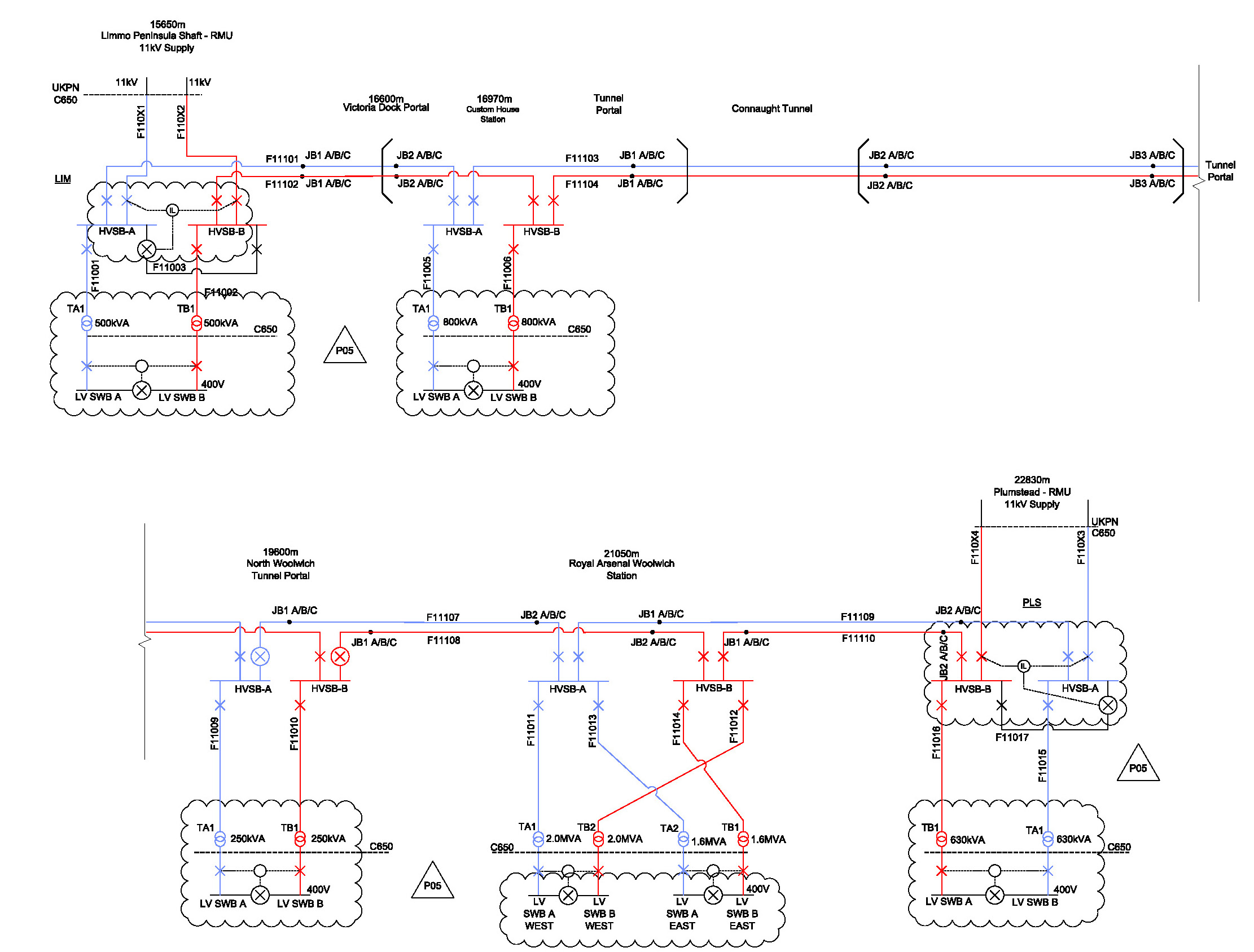 Figure 4. Elizabeth Line 11kV Network Plumstead to Limmo
The section from Canary Wharf to Royal Oak Portal, including the leg to Pudding Mill Lane Portal is fed at 22kV. This required the procurement of four separate 132/22kV Bulk Supply Points (N+3). Two of these are located at Limmo Peninsula shaft and were procured from UKPN. The other two are in West London and were procured from London Underground. 22kV power is distributed throughout this section of the project with HV-A running within the Eastbound tunnels and HV-B within the westbound tunnels.
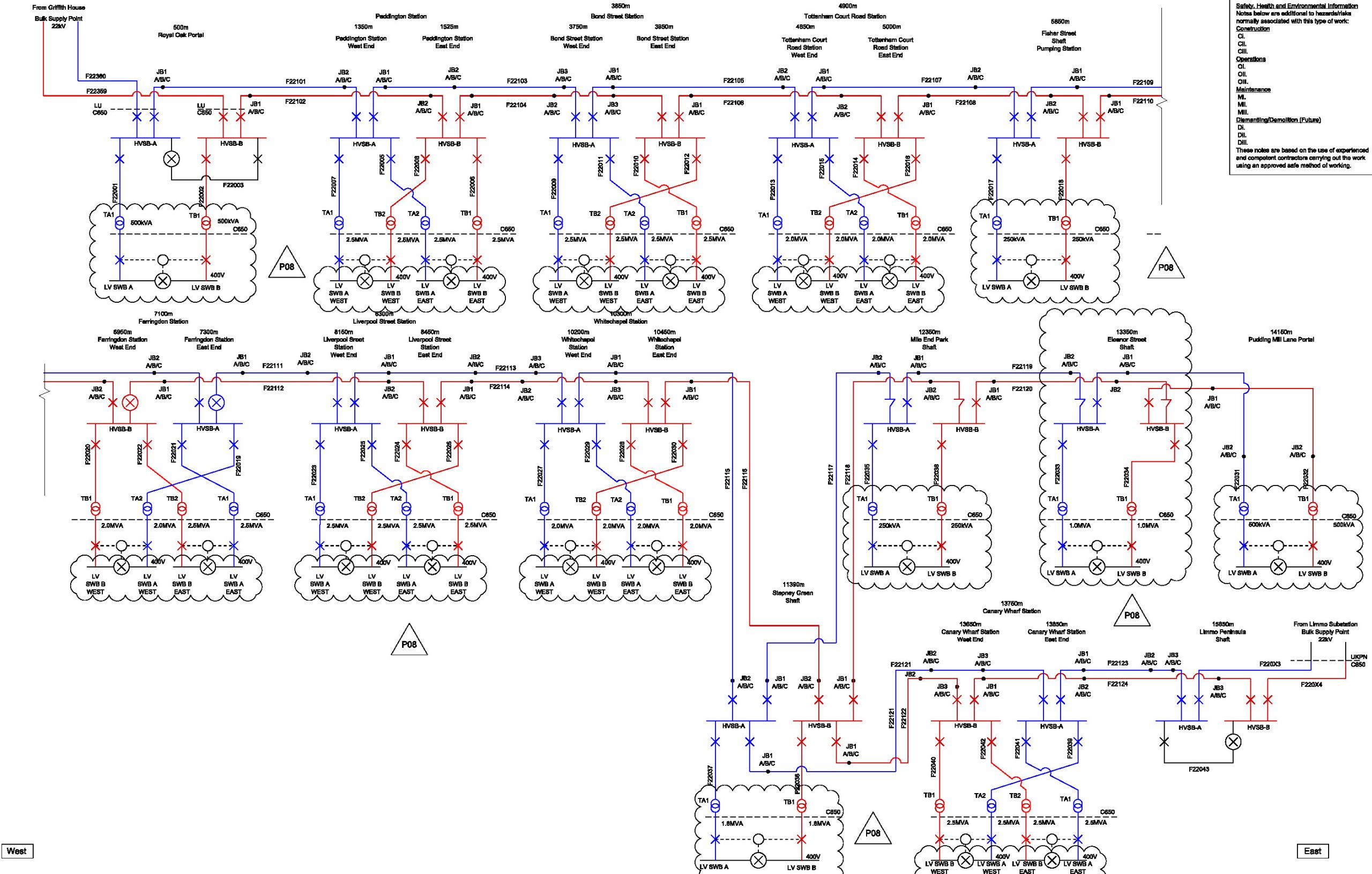
Figure 5. Elizabeth Line 22kV Network Royal Oak to Canary Wharf & Pudding Mill Lane
The relationship between HV & LV is best described by Figure 6. HV Cable A enters the station from the eastbound tunnel and via a dedicated fire protected HV-A cable riser, leaves trackside and enters HV Switch Room A. HV Switchboard A feeds Transformer TA1 (Local), and Transformer TA2 (Remote). Each transformer feeds an adjacent LV Switchboard A.
HV-B enters the station from the westbound tunnel and via a dedicated fire protected HV-B cable riser, leaves trackside and enters HV Switch Room B. HV Switchboard B feeds Transformer TA1 (Local) and Transformer TA2 (Remote). Each transformer feeds an adjacent LV Switchboard B.
The HV Switchrooms, Transformer Rooms and LV Switchrooms are all fire rated.
The LV Switchboards can bus couple through. When set to Auto (normal operating position) loss of supply from the transformer will result in the respective LV incomer opening, and the bus coupler closing. To prevent paralleling of the LV supplies, both incomers and the bus coupler are interlocked.
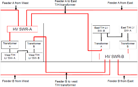 Figure 6. High Voltage/ Low Voltage relationship
Whilst the above system demonstrates a very high degree of resilience, with automatic transfer of loads from HV-A to HV-B at LV level, providing a 99.9% availability (one outage per year lasting less than a single engineering shift) this is insufficient to meet the requirements of the 2009 Regulations with regard to availability of telecommunications & emergency lighting systems.
Furthermore, National Grid is regarded by Transport for London as one source of supply, so despite the above, alternative back up is required. To that end, the Crossrail project specified the use of on-line UPS systems at each station, shaft & portal.
For this reason, the HV A+B networks are supported at stations, shafts & portals level by the on-line UPS systems outlined earlier within this document.
Could the Elizabeth Line benefit from a CEPS connection?
HV-A+B supplies in West London emanate from a London Underground BSP, so in simple terms, a CEPS connection is available. However, there are issues for the Elizabeth Line to overcome:
- This opportunity would only apply to the 22kV network as the 11kV network does not interface with any part of the LUL HV network.
- The 22kV Open Points are located at Farringdon East. Therefore, locations East of Farringdon are not generally connected to the LUL BSP, so do not have CEPS available. However, the open points could be moved or staggered to facilitate CEPS.
- The existing LV switchboards do not have load shedding capability, though this could be fitted.
- The existing UPS systems rectifiers are sized to suit the current battery size & quantity. To reduce the quantity of batteries, and thus have a financial benefit from a CEPS connection, the UPS would need to be replaced (Rectifier size & battery string size are joined at the hip)
With respect to the above issues, implementing CEPS to co-ordinate with UPS battery replacement is unlikely to be feasible. However, the life of the UPS itself is likely to be circa 20 years. Replacement of the UPS with a smaller system could make a CEPS connection feasible.
Introducing load shedding to all MCCBs within the existing LV switchboards except those feeding the UPSs should not be regarded as a show stopper, and this work could be undertaken in advance of the UPS replacement. This can be achieved by an “OPEN” command from the Railway Control Centre (RCC) to each LV Switchboard outgoing MCCB via System Control and Data Acquisition (SCADA). Each MCCB would require a shunt trip to be fitted, to open the MCCB when the command is received. This would require a single pair of SCADA input/outputs (I/Os). Closing post incident would have to be manual, unless each MCCB was also fitted with a motorised closing device. This option would also require another pair of SCADA I/Os to transmit the command from the RCC.
Moving both of HV Open Points, or staggering them would require some HV study works.
With the CEPS connection in place, the Elizabeth Line could reduce the autonomy of their UPS systems from three (General UPS) and four hours (Telecomms UPS) to just one hour.
At future Battery replacement time, the quantity of batteries to be re-installed could be reduced dramatically. This not only reduces CAPEX, it will also reduce OPEX for the battery charging load plus the HVAC systems that keep the battery rooms ventilated and cooled.
Future rail projects in London
For future rail projects in London, if a CEPS supply can be made available from the LUL HV network, there are considerable savings to be made in terms of cost, programme and space. Crossrail 2 for example will pass through Euston station where a connection to the LUL HV network and a subsequent Load Application for CEPS can be requested.
- As within existing LUL stations, the UPS systems only require autonomy of 1 hour to enable the CEPS generators to run up and come on-line. By reducing the UPS autonomy, there will be a significant cost reduction in CAPEX
- Batteries require replacement every 10 years. With a reduced quantity of batteries the replacement costs will be reduced (OPEX)
- Reduced battery quantity also reduces risk of injury to personnel (logistics).
- Reduced quantities of batteries result in reduced cooling costs, and size of cooling & ventilation plant, resulting in further OPEX & CAPEX savings.
- Reduced quantities of batteries will result in reduced room sizes.
A requirement of the LUL Power Engineer is Load Shedding. When powered from the CEPS supply, the designer must demonstrate that the only loads connected to the system after loss of supply will be those that fulfil the criteria of requiring a CEPS supply, generally lighting & communications.
The recommendation for future rail projects within London is therefore to design power supplies with at least two HV connections to the LUL system, with a provisional Load Application submitted to the LUL Power Engineer during the Feasibility stage of the project to reserve capacity from CEPS. Where an LUL connection is not available, then consideration for a private CEPS connection should be considered early in the project life cycle.
Load shedding options
To receive a CEPS supply from LUL, certain conditions must be met. Key to receiving agreement for a CEPS connection is the ability to guarantee that all non-safety critical loads are removed from the supply. There are two options to achieve this:
Individual load shedding
Sub main cables that take energy from the primary LV switchboards to points of utilisation are all terminated onto Moulded Case Circuit Breakers (MCCB’s). Capability exists that each one could have shunt trips fitted. On command from the control room via the SCADA system, each one of these will collectively switch to OPEN. This removes the connected load from the LV switchboard thus satisfying the requirements of the LUL Power Supply Engineer. The only loads that would not have this function would be those supplying safety critical loads, namely the UPS supplies including external by-pass. On restoration of the supplies, all OPEN MCCBs can be closed by SCADA signal, though this method will require each and every MCCB to include a motorised closing device. The alternative to fitting motorised closing devices is for station staff to close these manually.
Collective load shedding
Introduce an additional bus section to the primary LV switchboard. This will increase the length of the switchboard by at least 1500mm. A shunt trip within the bus section ACB could be remotely controlled by the control room operator. The Air Circuit Breaker (ACB) can be commanded to OPEN. On restoration of the supplies, the OPEN ACB can be closed by SCADA signal. This will require the ACB to include a motorised closing device, though this is very common with ACBs.
Typical costs associated with these works (August 2020) are as follows:
- 4,000A LV Switchboard new purchase price £200,000
- Additional Bus section with remote control £27,000
- Individual MCCB opening & closing with PLC £75,000
The above costings would need to be considered over the full life of the station, assuming battery replacement is every ten years, UPS replacement every 20 years and LV Switchboard upgrade/replacement is every 30-40 years.
Loads categories
Safety Critical
Loads to be fed from the UPS/CEPS supply are generally termed as being safety critical. Safety critical systems will receive their supply from A+B supplies via local Auto Transfer Switches (ATS) through UPS for:
General UPS
- Emergency Lighting
- OLE (Overhead Line Equipment) switches
- Tunnel Vent Damper control panel PLC
Telecommunications UPS
- CCTV
- PAVA
- Station Radio
All sub-main & final circuit cables to be 2-hour fire survivable and Low Smoke Zero Halogen (LSOH).
Operationally safety critical systems A+B supplies via local ATS
- Fire fighting Lifts
- Signalling
- Tunnel ventilation fans
- Tunnel ventilation damper control panel
- Station ventilation systems
- Station smoke extract fans
- Stair pressurisation fans
- PRM Lifts
- Critical pumps
- Tunnel lighting
All sub-main cables to be 2-hour fire survivable and LSOH.
Operationally critical systems, A+B supplies via local ATS
- Incline lifts
- Escalators
- Platform screen doors
- General lighting
- Station cooling systems
- Pumps
- Station ticketing (computers only)
All cables to be LSOH. No requirement to be 2-hour fire survivable if cables are segregated
Non critical systems, A or B supplies
- General small power outlets (kitchen & welfare) via local DBs
- Maintenance power outlets via local DBs
- Station ticket gates
- Water heaters via local DBs
- Outside lighting via local DBs
All cables to be LSOH. No requirement to be 2-hour fire survivable.
Systems noted above that are regarded as “critical” receive a dual supply fed via a local ATS. An indication of the complexity of these power supply systems is provided below.
HV/LV system architecture
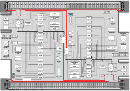
Figure 7. Typical station layout for LV power system architecture
Points to note:
- Sketch identifies the relationship between all operationally critical loads and the LV A+B power supplies.
- This sketch is diagrammatic only and must not be relied upon for any other reason than to understand how the LV system works.
- Note that the two UPS systems at each end of the typical station each have an A+B supply via a local ATS.
- To meet RAMS (Reliability, Accessibility, Maintainability, and Sustainability) targets the ATS is located adjacent to the UPS so that the single point of failure (the cable) is as short as practically possible.
Recommendation
Crossrail was built with a focus on having General & Telecommunications UPS systems at every site. A CEPS connection was not considered feasible as the HV non traction system was to be owned and operated by Network Rail. London Underground could not have used their CEPS to supply loads over a HV network over which they did not have control.
The recommendation for future new railways under the control of TfL is to include provision for a CEPS supply with designs based on this from initial concept.
-
Authors