Towards Integration of Engineering Services at Crossrail Stations, Shafts and Portals
Document
type: Technical Paper
Author:
Wing Fung PhD MSc BSc(Eng) CEng MCIBSE, Alec Wai Leung Chu BSc MA CEng MCIBSE MIET MIOL, Sidharth Dawar MSc MBA, ICE Publishing
Publication
Date: 30/09/2017
-
Read the full document
Introduction
Integration is the unification of the objects through their interactions of energy, matter and information to provide system level functionalities and performances. Integration is a collaborative, value enhancing approach to demonstrating functionalities and performances of products and services. Integration requires the structures of knowledge, the benefit of information, and meaningful data to determine the alternative ways in which to integrate a product and service. Integration requires a clear understanding of the dynamics at the interfaces between objects. An interface is within the boundary that separate two objects or two processes. Physical connection of two objects results in an interface. Functions occur at the interface between two objects.[1]
Crossrail is accountable for the overall delivery, programme management, design, construction, testing, handover, trial running and completion of the Crossrail Programme. The company is responsible for delivering an integrated and assured Central Section Railway including end-to-end interface works with Network Rail and all other relevant works. It is also responsible for integrating all the assurance evidence of the end-to-end railway in order to demonstrate that all works delivered by both CRL and its Industry Partners are fully integrated and the performance will meet the Sponsors’ requirements and support acceptance by the relevant Operators. Crossrail appoints competent designers and contractors to design and build the Central Operating Section. It is also responsible for accepting both the designs and built assets with the technical assurance evidence necessary to assure that it complies with the Sponsor’s Requirements.
Crossrail have established an assurance approach whereby the aggregated outputs are tested against the four pillars of technical assurance:
- Verify that the railway is collectively safe
- Verify that the railway is collectively maintainable
- Verify that the railway is collectively operable
- Verify that the railway will collectively perform to required levels of capability
Technical Authority is responsible for assuring that all CRL works comply with the Technical Assurance Plan. The Chief Engineers Group (CEG) is the Technical Authority for Crossrail. CEG consists of the following work disciplines: Civil and Structural Engineering, Construction, Architecture, Geotechnical, Mechanical Electrical and Public Health, Route Systems, Signalling, Bulk Power, Communications and Control, Human Factors.
CEG controls the overall engineering assurance process. It is the final acceptance body that provides overall completion certification for the Crossrail Central Section including its end-to-end interfaces works with the other Industry partners such as London Underground, Rail for London, Dockland Light Rail and Network Rail. The CEG review body is independent of the delivery group. This assures that the technical compliance of the Works with the sponsor’s requirements can be verified under least influence by project budget and programme constraints.
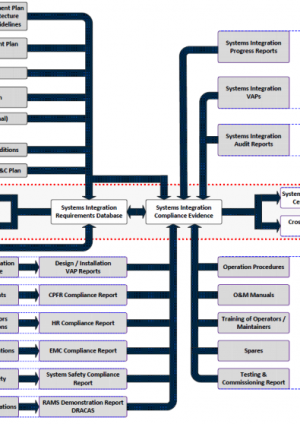
The contract strategy for the construction of stations, portals, shafts and tunnels works is that discrete construction work packages for are assigned to design build contractors. The work packages are demarcated by geographical boundaries. Railway system contracts are awarded on a line wide system by system basis. It is therefore of great importance that the packages are fully co-ordinated and integrated so that Crossrail will perform as a single integrated entity meeting all functional requirements even though they are designed and constructed under different work packages. Figure 1 below shows how the systems integration activities by the contractors interact with the CEG.
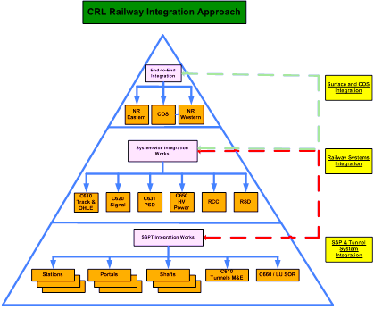
Figure 1 – Interaction matrix on systems integration activities
CEG has adopted a vertical integration assurance approach to accept, review and control technical and integration elements of the work packages.
Figure 2 at the end of the paper shows the process flow diagram to achieve integration of systems for Crossrail. All procedures, work plans and delivery schedules developed are to support the process flow. The contractors are expected to implement internal work processes to ensure that the component parts that make up the Crossrail rail system operate in a functionally correct manner across system interfaces and that they are coordinated at the interface.
This paper highlights the collaborative approach that Crossrail adopted to manage integration of engineering services for stations, shafts and portals.
Abbreviations
ATS Auto Power Transfer Switch BMS Building Management System CEG Chief Engineers Group, Crossrail CRL Crossrail Ltd. EMC Electro-Magnetic Compatibility ESM Engineering Safety Management ITP Inspection and Test Plan LVA, LVB Low Voltage Power Supply- Source A and B MEP Mechanical Electrical and Public Health RAM Reliability Availability and Maintainability RCC Route Control Centre SMS Station Management System SOR Station Operating Room T&C Testing and Commissioning TVS Tunnel Ventilation System UPS Uninterruptable Power Supply VAP Verification Activity Plan The Collaborative Approach
CEG works hand in hand with the railway systems team, project delivery team and contractors to integrate engineering services at the design, construction, T&C and handover stages. Key areas of focus are integration design control, a common integration database, interface management and integration tests.
Role of CEG
Design
An Engineering Design Assurance Gates procedure is adopted to provide progressive assurance during the design stage to confirm that the objectives of the project will be achieved and that the project can progress successfully to the next stage. The procedure covers a regime where agreed products and deliverables are submitted, reviewed and accepted. In the event that submissions are rejected the Assurance Gates provide a control mechanism for re-submission; and to provide clear visibility at progress checkpoints to ensure compliance to CRL’s broader governance and authority processes. At Gate Reviews, Crossrail seeks evidence that the Systems Integration processes have been correctly followed and that the Design Reviews have taken place and any issues raised have been closed out.
In the Design Phase, specific systems integration related documents to be presented by the contractors for review by the Crossrail are Interface Control Documents, record of interfaces with framework suppliers (e.g. Lifts & Escalators, Building Management System etc.), Systems Integration Management Plan, Testing & Commissioning Plan/Strategy, Systems Breakdown structure and identification, Systems Commissioning Lots structure and identifications, RAM Demonstration Plan, Human Factors Plan, Electro-mechanical Compatibility (EMC) Plan, Evidence of compliance with Crossrail Functional Requirements, Room Data Sheets, Engineering Safety Management Report, Systems Architecture, Alarms Strategy / Matrix, SCADA I/O List, BMS I/O List.
The review is to ensure that they deliver a completed, compliant, co-ordinated, and integrated design. CEG maintains record of reviews in the eB database management system. The latter system also contains a computer based Work Order and VAP (design stage) modules to facilitate centralized management of the business processes.
Construction
CEG provides technical support to the field supervisors to ensure that integration issues are identified, addressed in a timely manner. Some of these issues are details of interfaces, configuration control, RAM reviews and change control. VAP(systems integration- construction) has also proved to be an important tools to ascertain that system integration process is being implemented effectively, in particular in confirming that construction related integration evidence are captured and integration tests are being developed for execution upon completion of work. CEG also liaise with field engineers to identify Hold Points in the Inspection and Test Plans (ITP). The integration surveillance work by CEG targets high risk items in the unlikely event that the final deliverables are not fully integrated. Upon completion of installation work and before commissioning CEG will liaise with field engineers to ensure that plant and equipment is installed in accordance with the assured design, including space for access, maintenance, replacement etc. On material compliance control, CEG will collaborate with field engineers to ensure that all plant and equipment procured / installed is in accordance with the material compliance review procedures. Sample review equipment suppliers manufacturing and shop drawings, installation drawings and standard details are carried out. The review process includes review red-line and as-built drawings, final design, raise and close-out non-conformance reports, and generate VAP Reports to support the incremental acceptance of works leading into Handover.
Testing and Commissioning
CEG monitors the contractor’ systems integration work through progress reviews of T&C work against completeness of documentation, review of T&C test reports, witness integration tests,
Handover
Prior to contract handover, CEG will check that the completed work is in accordance with the final design, review of as built drawings, three dimensional Building Information Management (BIM) computer model, asset tagging and red-lines drawings; review of contractor’s Operation and Maintenance manuals and Verification and Validation reports; review of Handover Packages; review of ESM and Safety related files and justifications, and check for completeness of systems integration deliverables.
In the project handover phase, Crossrail will consolidate the systems assurance records from the contactors and confirm that the railway is fully integrated and fit for operation. CEG will also confirm that the content of the handover packs are suitable for the purpose.
Role of Contractors
At the design stage, the contractors have to produce evidence of design integration timely and in a quality manner.
At the construction and T&C stages, the contractor will provide evidence, in progressive manner, that the deliverables are fully integrated with deliverables of other work packages and systems integrated plan is implemented effectively.
At the contract handover stage, the contractors will provide consolidated technical assurance evidence including compliance certificates, CARE database, Operation & Maintenance Documentation demonstrating that the products delivered are fully co-ordinated, interfaced and integrated.
Responsibilities Matrix
It is important to carry out systems integration works in a co-ordinated manner with a clear roles and responsibilities. The following matrix outlines the role of CEG and contractors in specific systems integration work tasks.
Table 1: Responsibility Matrix- Systems Integration
Specific systems integration tasks Responsibilities Contractors CEG Interface Nodal Points and technical requirements Identify and agree all interface nodal points and technical requirements
Develop Systems Architecture to provide an overview of systems integration scope under Contract
Develop preliminary systems architecture diagram for adoption and development by contractors as appropriate.
Review evidence presented by contractors on interface nodal points and agreement with interfacing parties on technical requirements
Interface Control Agree key system interfaces and data exchange protocol with system wide contractors and capture in ICDs
Agree key system interfaces and data exchange protocol with framework suppliers and maintain records of internal interfaces in eB
Review assurance evidence presented by the contractors
Monitor development and implementation of ICDs and internal interfaces
Testing and Commissioning Plan Develop Breakdown structure for engineering systems
Develop ComLot structure and T&C Logic Sequence
Develop T&C plan
Co-ordinate and align with Master T&C Schedule
Review assurance evidence presented by the contractors
Check that the T&C programme is in alignment with the Master T&C Schedule
Monitor development and implementation of T&C Plan
T&C Tests Implement T&C plan and compile test reports
Update T&C database
Review test reports
Witness critical tests as per CEG Systems Integration Progress Management Plan
Physical conformance with approved design Abide by change control procedure on design change (design drawings, materials and specifications) Review VAP records for adequacy and effectiveness
Implement Systems Integration related VAP
Key system performance and life safety functionalities Check that T&C regime covers verification of system performance and life safety functionalities
Carry out test and compile test reports
Witness tests as necessary and identified in the ITP, and review test reports Key interlocking functionalities Check that T&C regime covers verification of key interlocking functionalities
Carry out test and compile test reports
Witness tests as necessary and identified in the ITP, and review test reports Interface compliance and handover Agree interface specification and handover programme with interfacing parties
Execute interface plan and provide evidence of compliance
Witness sample tests and review implementation of interface plan Verify meeting earthing and bonding requirements Provide deliverables as per approved Earthing and Bonding Plan Review test reports
Witness sample tests
Verify meeting EMC requirements Provide deliverables as per approved EMC plan Review test reports
Witness sample tests
Verify meeting ESM requirements Provide deliverables as per approved ESM plan Review compliance reports
Verify meeting Human Factors requirements Provide deliverables as per approved Human Factors Plan Review compliance reports
Carry out random checks in VAP
Verify meeting SOR integration requirements Provide deliverables as per agreed integration requirements for SOR Review test reports
Witness sample tests
Verify meeting RAM requirements (in particular, validate key RAM assumptions made in analysis) Provide deliverables as per RAM plan Review test reports
Witness sample tests
Demonstrate end to end functionalities for BMS 100% end to end functionality tests Review test reports
Witness sample tests
Demonstrate end to end functionalities for SCADA 100% end to end functionality tests Review test reports
Witness sample tests
Complete dynamic testing (performance as a fully function railway) Provide attendance and support as needed in dynamic tests Review test reports
Witness sample tests
Stress Tests and performance tests relating to degraded operation/ specific operation scenarios Check that T&C Plan cover different operating scenarios (normal, degraded and emergency) Review test reports
Witness sample tests
Test and conformity certificates Provide assurance evidence to support test certificate Review assurance evidence
Carry out random audits on test database
T&C documents Maintain T&C records in a structured and traceable manner using agreed templates Review T&C documents
Carry out random audits on T&C database
Handover documents Produce handover documentation using agreed templates Review handover documents Training Conduct training as per agreed training plan Review training plan and records for adequacy and effectiveness Critical tools and spares Deliver tools and spares as per agreed plan Review tools and spares provisions for adequacy and effectiveness Certification of completion of systems integration programme Provide evidence of compliance Review assurance evidence presented Confirm completion of systems integration activities Compile final report on compliance of Crossrail systems integration requirements Configuration Management at Interfaces
In Crossrail, there are situations where performance of safety or mission critical functions requires action of engineering systems constructed under different work packages. To allow concerted action of these systems, effective information transfer via the designated nodal points at the physical boundary between the systems has to take place. Interface nodal point is the location(s) where transfer of energy, matter or information from one system to another will take place in order to achieve a set of meta-system functions in which all the component systems participate. In the context of stations, shafts and portals, the information transfer refers to passage of control and monitoring data between MEP installations and Railway System installations / framework suppliers/ third party installations at the interface panel at the designated plant rooms. Table 2 provides a generic list of the key interface nodal points for MEP installation at stations, shafts and portals. The actual list of interface nodal points is provided in the Combined Services Drawings/ System Architecture Diagrams developed by the contractors.
Table 2: Interface nodal points for mission or safety critical systems
Railway System/ Framework Supplier/ Third Party Installations MEP System VCS Platform smoke extraction SCADA BMS SCADA Fire Alarm Panel SCADA Sump Pump SCADA UPS SCADA Staircase Pressurisation and Air Release SCADA Main Switchboard Gate line Fire Alarm Panel SMS Lift SMS Escalator BMS Lighting Control BMS UPS Third party installation (for interchange stations) Fire Alarm Panel An early understanding of the interface details at the construction stage is essential to reduce the occurrence of integration problems at the testing and commissioning stage. Furthermore, a clear picture of protocols for interface nodal points facilitates technical configuration control on the hardware and software for the interfacing systems and verification activities while managing the systems integration process.
Details of interface nodal points are captured in the systems integration database in a structured manner to ensure there is a line wide consistency on keeping interface information. The list of technical information for the key interface nodal points for stations, shafts and portals is shown in Table 3.
Table 3: Technical Information related to Interface Nodal Points
Explanation/ Examples Station/ Shaft/ Portal Contract Number Interface Nodal Point Reference A reference number for the interface nodal point.
Example: C5xx/INP/ES /001 (Contract C5xx/ Interface Nodal Point/ Eastern Shaft/ Point 001)
Interface Control Document Reference eB number of the document Location of Interface Room Number where the interface takes place Interfacing parties Example: VCS and Platform smoke extraction Physical Interface including list of terminal points Example: Hardwire Interface: Marshalling Panel (Panel by Tier 1, CMS by Tier 1, Cable by C610, termination by C610)- re panel layout (eB xxx); List of interfacing point: re eB xxx Details of interface Example: DIR (eBxxx); IRS (eBxxx); Minutes of discussion in interface meetings (eB xxx); Drawing Reference (eBxxx) Details of software interface protocol (with version number) Example: Microsoft Window Version xxx Related Document Related document to the nodal point Integration Tests
Integration Tests are the key verification and validation activities to demonstrate successful integration of the railway functional elements. Table 4 provides an illustration of some of the integration tests to be carried out for the stations, shafts and portals to satisfy the technical assurance requirements with respect to integration of the various services for the areas. It is not an exhaustive list and does not include all integration tests that will be carried out for the stations shafts and portals.
Table 4: Examples of Integration Test for Stations Shafts and Portals
Integration Test Integration Criteria End to end tests for BMS (interface between BMS with RCC, SMS, Maintenance Depots System Performance End to end tests for systemwide control and condition monitoring system System Performance Operation of pressurisation system when Tunnel Ventilation System (TVS) is in operation-Door opening force, Opening of firefighting lift door, Minimum velocity through the open stair door, Static pressure differentials between staircase/ lobbies and protected routes. Details of test as stipulated in Testing and Commissioning of Fire Fighting Staircase Pressurisation and Air Release System Safety Integrated test on operation of Tunnel Ventilation System (TVS). TVS in concert with platform smoke extraction system- Demonstrate the correct sequence of operation of TVS and platform smoke extraction as stipulated in the TVS Mode Table. System Performance Verify result of impact assessment on loss of BMS LAN on Line wide railway system equipment, MEP plant, functionalities of SMS, panels at SOR and station remote control/ monitoring functions at RCC System Performance Verify result of impact assessment on loss of LVA, LVB and both LVA & LVB on Line wide railway system equipment, MEP plant and functionalities of SMS panels at SOR and station remote control/ monitoring functions at RCC. System Performance Verify operation of tunnel light fed from station power supply on loss of LVA, LVB and both LVA and LVB. Verify control of tunnel lighting from SSP and tunnels, operation of push buttons, directional signage etc. Verify integration of lighting of emergency escape paths from tunnels to stations or shafts or portals System Performance Verify correct bonding of station equipment on to traction earth. Safety Verify that design door opening and closing force (public circulation route, evacuation and intervention routes) is not exceeded with the operation of TVS, Platform Smoke Extraction System and simultaneous operation of TVS, platform smoke extraction and pressurisation/ air release systems. Safety Validate effectiveness of platform smoke extraction system using smoke bombs with and without operation of TVS. Where there are environmental restrictions on the use of smoke bombs, alternative validation method shall be established. Safety For stations where platform smoke extraction is connected to TVS ventilation shaft, damper interlock test. System Performance Dynamic response test for FCR cooling when TVS is in enabled and run System Performance Validate that permissible draft air speed at escalator barrels and passageways is not exceeded under normal condition; with the operation of TVS and under train piston effect System Performance For interchange station- demonstrates that grey alert signal is fully functional. System Performance Stress test- changeover of platform smoke extraction from eastbound and westbound platforms within 90 seconds and vice versa from RCC System Performance Demonstrate compliance with design room noise levels: Integrated acoustic test for MEP plant- inside plant room and breakout noise from plant rooms. It is noted that this test incorporates multiple MEP elementary systems. It cannot therefore be covered in a single Commissioning Test Plan. Where applicable, tests to be carried out with and without operation of the systemwide equipment inside the equipment room System Performance Verify that firefighting lift doors will operate normally under fluctuations in air pressure under train piston effect and while TVS/ pressurisation system is in operation System Performance Demonstrate loss of LV power will not impact Emergency Lighting and Fire Systems and demonstrate UPS power is available to the relevant systemwide equipment via the appropriate ATS System Performance Demonstrate during power restoration the plant and equipment restart and reset automatically in accordance with design requirements System Performance Demonstrate fire alarm cause and effect on Line wide railway system installations. The test should also demonstrate control action on the fire panel System Performance Reliability Tests- The reliability tests are intended to reduce infant mortality as far as possible. Details of test as stipulated in Reliability Tests for MEP Installations at Stations Shafts and Portals System Performance Crossrail Assurance Reporting Environment (CARE)
All Systems Integration and Assurance evidence generated through the contractors are recorded in the CARE database. The relevant information is recorded onto CARE database at the appropriate locations as per the CARE Systems Breakdown Structure. This evidence will support during the Handover and progressive acceptance of Systems and finally for Assets at each location.
The format and level of details of documentation presented by the contractors to demonstrate compliance with systems integration requirements are described in the contractors’ Verification &Validation Plan. They are in the form of independent checks, type test reports, field tests, integration tests etc. Table 5 provides a summary of information to be provided by the contractors to demonstrate that a robust systems integration programme has been implemented.
All systems integration work information related to the effective implementation of systems integration activities are captured in the eB system in Crossrail (an electronic information system).References
[1] Gary O. Langford, Engineering Systems Integration- Theory, Matrices and Methods, CRC Press, 2012
Table 5:Summary of information related to Systems Integration
General information
Systems Integration details
Process management Systems Integration technical aspects Systems Integration reference number
Control document
Revision
Approvals
Date last updated
Quality information – author, reviewer, approver
Revision history
Description of the systems integration element covered by the document
Systems Integration parameters need to be defined and resolved in the ICD or other project documents
Systems Integration functional description – the functional requirement of the Systems Integration
Systems Integration technical description – the technical aspects of the Systems Integration necessary to fulfil stated purpose of the ICD or other project documents
Configuration and demarcation points – identify the configuration of the Systems Integration along with the demarcation points of each partner’s works
Scope of work – define each Systems Integration partner’s scope of work up to the demarcation point
Interfacing entities
Systems Integration type
Requirement source
Intent
Safety critical details
Assumptions, dependencies, constraints
Risks
Systems Integration owner declaration
Documentation and communications
Data and configuration management
Requirements and assumptions,
Risk and issues management
Hazard management
Dependencies and constraints management
Key performance data
Spatial requirements
Weights
Mounting or fixing requirements
Access requirements
Electrical load
Heat dissipation
Environmental requirements
Control System Integrations
Data communication requirements
Electromagnetic compatibility requirements
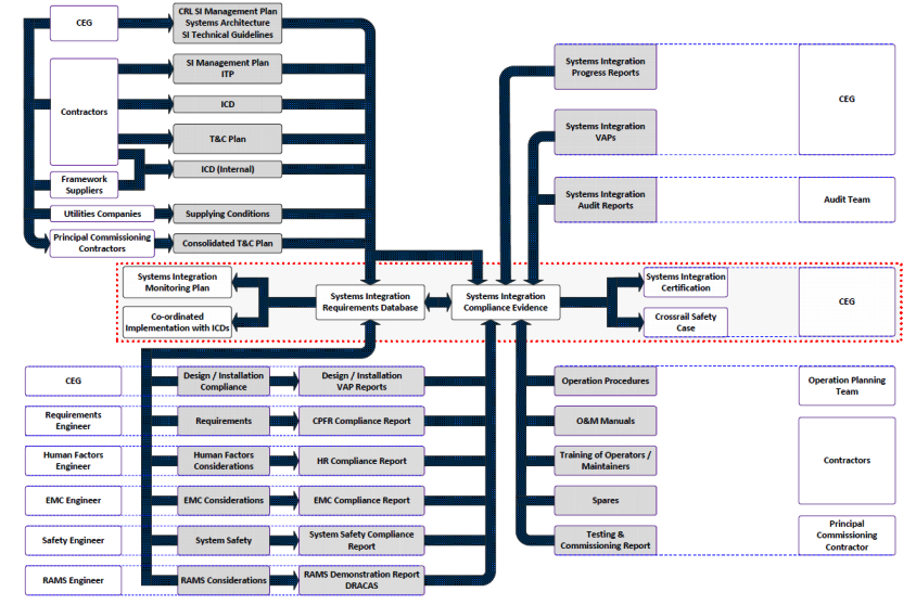
Figure 2: Process Flow Diagram for Systems Integration Activities at Crossrail Stations Shafts and Portals
-
Authors

Wing Fung PhD MSc BSc(Eng) CEng MCIBSE - Arcadis
Technical Director (MEP), Arcadis
Wing is is a Chartered Engineer with over 30 years’ experience as a technical specialist engaged in mass transit system planning, design, project management, technical assurance, commissioning, energy management, operation and maintenance, and asset renewal. Wing has been with the Crossrail project in the CRL Chief Engineer Group since 2013, overseeing mechanical design, systems integration and T&C.
Specialties: Building Services, Mechanical Engineering, Computational Fluid Dynamics, RAM studies, Systems Integration, Requirement Management, Testing and Commissioning.

Alec Wai Leung Chu BSc MA CEng MCIBSE MIET MIOL - Crossrail Ltd
MEP System Integration Engineer, Crossrail
Sidharth Dawar MSc MBA - Crossrail Ltd
Former Systems Assurance and T&C Verification Manager, Crossrail
