Tunnelling out of a drift filled hollow under Moorgate
Document
type: Technical Paper
Author:
John Davis EurGeol CGeol MSc DIC, Roser Soler Pujol, Nigel Hill, Dr Alfred Stärk Dipl Ing Dr Ing, ICE Publishing
Publication
Date: 09/07/2018
-
Read the full document
Drift Filled Hollows in the London Basin
Drift Filled Hollows (DFHs) are anomalous, often steep sided depressions in the upper surface of the London Clay or other pre-Quaternary strata. These depressions are usually infilled with Quaternary strata (‘Drift’) or melanges of Quaternary strata and pre-Quaternary strata. The most common infilling materials are sand and gravels generated by Pleistocene glacial outwash to the north of London in the early warming phases between glacial and interglacial cycles. These materials were laid down in successively lower floodplain terraces by the River Thames and its tributaries. These are the ‘River Terrace Deposits’ (RTD). The largest DFHs found to date are several 100m across and 10s of m deep. In some cases DFHs provide a hydraulic connection between the upper and lower aquifers in London.
Such features were first described within central London by Berry[1] in 1979. Berry identified 27 of these so called ‘scour hollows’. Ongoing work for publication by the first named author and others has so far identified 80 DFHs within London.
A significant proportion of these features were found during tunnelling works, often unexpectedly and often leading to significant difficulty. During tunnelling a sharp change in ground conditions from an over-consolidated London Clay to an un-consolidated water bearing drift material represents a significant hazard.
The origins of the DFHs are unclear. They are often associated with faulting and with current or historic watercourses, especially at confluences. Current thinking suggests the features start as significant river scours during the Pleistocene (the ‘ice age’) when flow volumes and energies early in warming phases were significantly higher than seen today. If these scours became deep enough then high artesian pressures in the lower aquifer may have instigated basal failures in the scours. Pleistocene artesian pressures are likely to have been significantly higher than those experienced within the span of recorded history. These hollows (failed or not) are likely to have become the focus for repeated development and collapse of significant ground ice wedges in structures called ‘Pingos’.
Modern day Pingos can be seen inside the Arctic Circle, particularly near the northern coast of Canada in a permafrost/tundra landscape. They are particularly well seen near the mouth of the Mackenzie River where they take the form of large earth mounds with an ice core.
These environmental conditions are similar to those that would have been found in London during the creation of the DFHs and the deposition of the RTD. Remnants of Pingos are also recognised in Wales and Norfolk. Many larger DFHs in London are associated with some indication of disturbance within the infilling materials and/or disturbance or uplift of underlying strata.
Crossrail and other structures
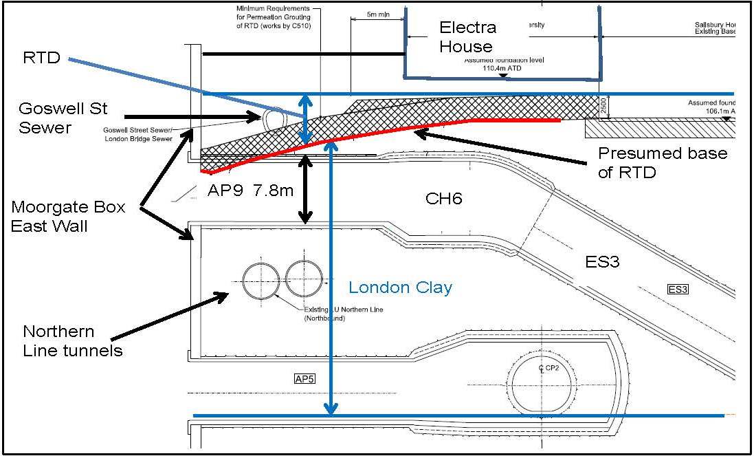
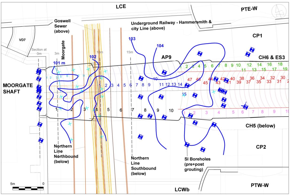
Crossrail’s 40m deep Moorgate Box now occupies the space previously taken by a demolished building between Moorgate and Moorfields. The Moorgate Box links the Liverpool Street platform tunnels at the western end of the Crossrail station to the ground surface. The upper part of the Box also receives a shallow 7.8m diameter horizontal SCL tunnel that passes over the twin Northern Line tunnels and under Moorgate with the crown 10m below ground level. This tunnel was called AP9 and CH6 and it links the Box with the top of an inclined escalator shaft east of Moorgate called ES3. See Figure 1.
East of Moorgate the AP9/CH6 tunnel, still at shallow depths, passes under Electra House before becoming ES3 and descending to platform level. Electra House is an Edwardian masonry clad steel framed building with a basement that was extensively damaged by incendiary bombs in 1941.
Moorgate Box was constructed using diaphragm walls (Dwalls). Within the Box the design incorporated two temporary east – west strutting diaphragm walls. Their purpose was to protect the Northern Line tunnels under Moorgate from excessive inwards deflection of the eastern Box wall during excavation. These strutting walls were progressively removed and replaced by permanent ring beams and temporary props as the Box was excavated.
AP9 and CH6 were excavated out from Moorgate Box towards the position of the top of the escalator shaft ES3 after the Box excavation and construction were complete. ES3 was later mined upwards from platform level to meet the already completed AP9/CH6. See Figure 1.

Figure 1. East – west cross section through the east wall of Moorgate Box, the western end of Liverpool St. Station, other tunnels and the presumed base of RTD.
Initial ground conditions and tender design for AP9/CH6
The geological sequence in and around Finsbury Circus is typical of central London. Namely: Made Ground / Alluvium / RTD / London Clay / Lambeth Group.
Ground level is approximately 113m above Tunnel Datum (maTD) where Tunnel Datum is minus 100m OD. Other than close to the Moorgate Box the base of the RTD is generally at or about 106 maTD. There is evidence of faulting and Lambeth Group Sand Channels at the east end of the station under Blomfield Box, but not elsewhere to any significant degree. The RTD in the area is from the Taplow Terrace, close to the northern edge of its floodplain and is normally around 4m thick. It is seen to be formed of the typical sands and gravels. The normal thickness of the London Clay in this area is approximately 30 m.
A perched groundwater table is found in the RTD at around 107 maTD.
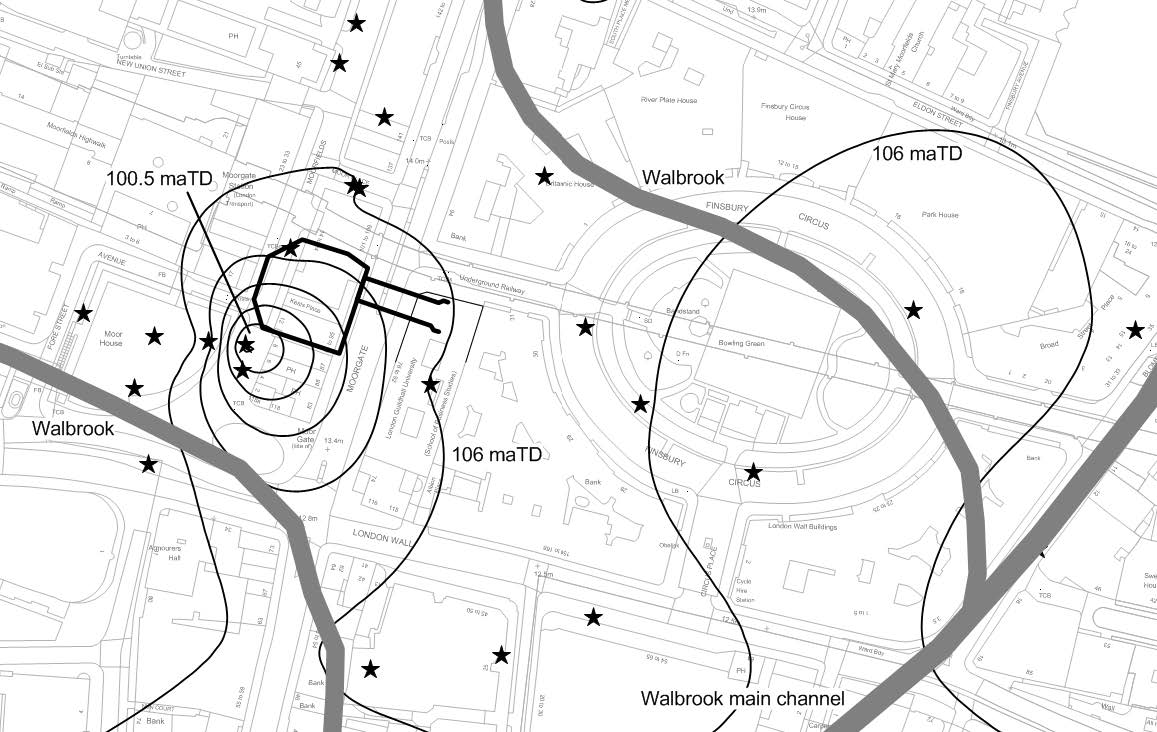
The main Walbrook channel (a Thames tributary) flowed down what is now Blomfield Street with several possible tributaries from the north west crossing the Finsbury Circus / Moorgate area. The repeated occurrence of ‘Moor’ in local place names (Moorgate, Moorfields) is indicative of locally poor surface drainage around these north western tributaries. The surface drainage pattern was probably significantly affected by the construction of the Roman City wall and associated moat across the southern side of Finsbury Circus.
At Moorgate Box a significant number of below ground obstructions (many utilities including the important Goswell Sewer, three London Underground tunnels and Moorgate Station) severely limited the opportunities for ground investigation before demolition and construction began. At this time (2010) this limited ground investigation suggested a wide shallow 6m deepening of the top of the London Clay centred a little way to the south of the Box. The RTD in these boreholes overlaying the London Clay was not unusual and dominated by sands and gravels.
See Figure 2.
The AP9/CH6 design response to this was to presume that AP9 would encounter water bearing RTD in the crown adjacent to the east wall of Moorgate Box, with the rest of the tunnel being entirely in London Clay, see Figure 1. This presumption and the closeness of the Electra House foundations east of Moorgate were mitigated in the design by requiring the Contractor to use a pipe arch around the crown of AP9 for the breakout from Moorgate Box and to permeation grout the RTD above the full length of AP9/CH6. All other temporary works arrangements including SCL excavation sequences were left for the tunnelling Contractor (C510/BBMV) to develop.

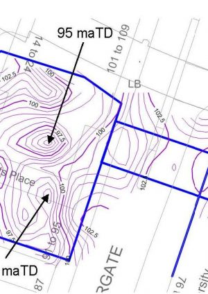
Figure 2: Contours on of the base of the Taplow Fm based on pre-construction CRL boreholes, possible courses of the Walbrook and its tributaries are also shown. [6]
(maTD,1m interval, stars = data points)
Construction of Moorgate Box, grouting and development of the ground model
Construction of Moorgate Box by C501/BNK began to reveal more information about the form and content of the DFH:
- The top of London Clay in a temporary works CFA contiguous piled wall on the south side of the Box was much deeper in places than anticipated (circa 98 maTD)
- Removal of existing CFA piles that had supported the demolished building found that they were irregularly oversized in the RTD (circa 1000 to 1200mm compared to the 900mm design diameter) over a significant depth.
- Minor casing base/piping failures occurred during pile removal – these are attributed to the presence of clay layers within the predominantly permeable sandy DFH infill.
- Instrumentation boreholes within the box footprint found typical RTD down to 95.5 maTD and found that the infilling materials were predominantly sand and gravel with some thin sandy gravelly clay layers.
Additionally RTD / London Clay interface measurements taken during Dwall construction and excavation started to reveal a complex DFH shape with the deepest point being approximately 95.5 maTD.
During excavation of the Box C510/BBMV began permeation grouting under Electra House and Moorgate. This extensive ground treatment programme was undertaken to strengthen the RTD and reduce its permeability in an annular 6m radial envelope around AP9/CH6. The grouting was mostly carried out using combinations of cement, fine limestone fillers and colloidal silicate grouts in multiple phases.
The treatment was conducted in a several stages from both the basement of Electra House and from Moorgate box. A series of Tube à Manchette (TaM) fans were installed to cover the crown of AP9/CH6. External programme constraints meant the injections undertaken from Moorgate box were interrupted for a long period, making it potentially difficult to later complete the grouting in the partially treated ground between the Dwall and the Goswell sewer.
Information on the elevation of the RTD / London Clay interface was gathered from the installation of the TaM grout pipes and added to the ground model.
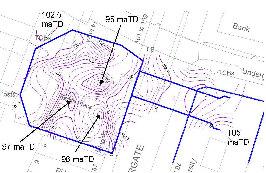
Plotting all this RTD / London Clay interface data together (see Figures 3 and 4) suggested that in AP9 slightly more RTD would be encountered over a slightly longer length adjacent to Moorgate Box compared to the tender assumption. At the time this was not of particular concern because the grouted RTD under Electra House had already been cored and seen to be well grouted and the excavated RTD within the Box was seen to be similarly groutable sand and gravel.
Note the location of the Northern Line tunnels in Figure 4. Their crowns are some 7 to 8m below the top of the London Clay and approximately 3.5m below the invert of AP9.
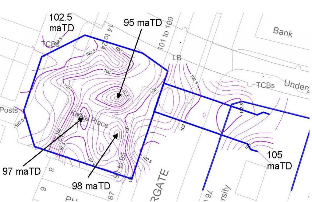
Figure 3. Contour plot of the base of the RTD within Moorgate Box, under Moorgate, and under Electra House. The plot uses all data sources – approximately 700 data points, locations are omitted for clarity (maTD at 0.5m intervals).

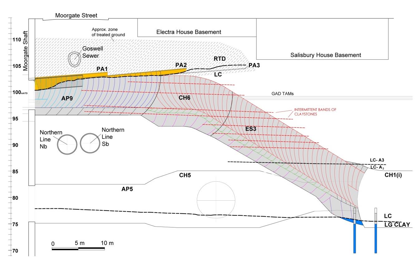
Figure 4: Longitudinal section of AP9, CH6 and ES3 tunnels showing RTD/London Clay interface within the tunnel crown and showing the SCL excavation stages and pipe canopy arrangements (PA1, PA2 ad PA3).
The now well defined shape of the DFH combined with occasional and surprising ingresses of displaced ‘grouty’ water into the Northern Line tunnels during permeation grouting indicated the possibility of larger scale open joints within the London Clay. This in turn gave rise to concerns about the possibility of significant ‘greasyback’ failures during mining of AP9/CH6.
Additionally during excavation of Moorgate Box the inward movements of the Box walls were unexpectedly much greater on the east side (adjacent to Moorgate) than on the other sides of the Box.
Some of the excavation was concurrent with the permeation grouting and there also appeared to be an unexpected relationship between some of the east wall movements and episodes of permeation grouting.
These occurrences taken together with the ‘lumpy’ shape of the base and east wall of the DFH suggested the possibility that the London Clay outside the DFH feature had experienced some disruption or slope failure during its formation.
The geological features within and around the DFH are summarised in general terms in Table 1 below.
Table 1 Geological characteristics away from and within the DFH
Strata Away from the DFH In the DFH Alluvium Intermittent Slightly thicker, but this may be related to the nearby presence of the Roman City wall and ditch. Taplow Fm (River Terrace Deposits) thickness ~4 m ~ 15m London Clay Fm thickness and character. ~30 m ~ 20 m
The London Clay excavated below the DFH appeared to be entirely normal. There was no evidence of faulting, large scale open joint systems, groundwater flow or other disturbance or distortion.
Lambeth Group Presence of intermittent Sand Channels within the Upper Mottled Beds and Laminated Beds Presence of very minor /thin Sand Channels within the Upper Mottled Beds and Laminated Beds compared to elsewhere at Liverpool St. Station. Mining constraints for AP9/CH6
AP9 is approximately 23.5 m long, it links Moorgate Box to CH6 and then to the inclined escalator shaft ES3, which in its turn connects to the concourse tunnels at the lower level of Liverpool Street Station. ES3, CH6, and part of AP9 cross directly below the existing basements of Electra House and the neighbouring Salisbury House, where the assumed basement foundation levels are 110.4m ATD and 106.1 m ATD, respectively (see Figure 3).
At AP9 there is a general overburden cover of 10 to 11 m below Moorgate, but this is locally reduced to just 1.5 m below the invert of the existing Goswell Sewer; and to circa 6.5 m below the Electra House basement. The tunnel dimensions vary along the axis in a trumpet shape to accommodate the installation of 3 consecutive pipe canopies, so that the extrados diameter of the tunnel is between 7.7 m, at the opening; and 9.6 to 10 m at the end of the first and second pipe canopies, respectively.
ES3 and CH6 vary between 8.5 and 10.8 m in vertical outside diameter, with an overburden of approximately 21 m at the lowest part of the Escalator under Salisbury House Building, 8.1 m below the party wall between Salisbury House and Electra House; and circa 7.4 m under Electra House basement.
Additionally, the tunnels cross approximately 3.5 m above the existing Northern Line running Tunnels, and are also parallel to the existing Hammersmith and City Line structure which runs to the North.
Contact with the contents of the DFH in the tunnel crown was to a greater extent than presumed in the tender. However the pipe arch and grouting were intended to mitigate the risks (uncontrolled inrush of material and excessive settlement) of mining into unconsolidated water bearing granular materials close to the crown of the tunnels.
Construction strategy – post grouting mitigation measures
Verifying the ground model
A ground investigation was completed for the initial Electra House stages of the grouting programme to establish the RTD/LC interface and obtain permeability parameters of the treated granular materials. The results showed well grouted typical RTD and the now expected lower level and irregularity of the interface with the London Clay. A 3D model of the tunnel with the RTD/LC interface and nearby assets was created to provide a better understanding of the geometry. See Figure 4.
Several holes were then drilled through the Moorgate Box Dwalls at what would become the AP9 opening and these encountered significant water flows out of the ground.
Measurements undertaken showed flows of circa 30 l/min [8] and a piezometric level at 106.25 m ATD, which is 3.5 m above the crown of AP9 at the opening in Moorgate and which approximately, corresponds to the axis of the Goswell Sewer. SCL mining was not possible in this scenario.
This raised the possibility of incomplete grouting or the possibility that the wall of the Box had moved away from the grouted ground allowing a water path in from neighbouring ungrouted ground. Any encounters with groundwater and/or flowing ground during SCL mining would have been extremely dangerous and difficult to control.
At this point ground freezing began to be considered in parallel as an alternative construction technique should the developing conventional mitigations be considered to be inadequate.
After further grouting in the breakout area further ground investigation was undertaken adjacent to Moorgate Box. This investigation revealed the unexpected presence of inter-bedded sandy and clayey layers in complex small channels at the London Clay interface within the confines of AP9/CH6. See Figure 5.

Figure 5: Contour of the London Clay / Taplow Formation interface based on information provided by pre and post-treatment Site Investigations works (TaM drilling data not included) against AP9, CH6 and ES3 excavation stages plan view.
Revisions to the tunnelling strategy
These findings prompted a series of revisions to the tunnelling strategy.
1)The concept of the single pipe arch was amended to a series of three nested and flared pipe canopies. This was because of concerns over the ability to install a single long flat arch with sufficient accuracy to avoid the steel pipes ‘drooping’ into the tunnel alignment. The canopy was anticipated to limit uncontrolled in rush of any ungrouted ground should any be encountered in the mining. The installation of the first pipe canopy raised further concerns when small pieces of painted timber were found in the ground under the Goswell sewer. The only likely sources of painted timber in this location were Victorian temporary works for the sewer construction. This caused two concerns. Had these structures impeded grout flow?; and were there temporary works drains under the sewer acting as high capacity groundwater conduits ? (as contemporary construction drawings suggest). Water ingress, geology and borehole collapses were all recorded during the pipe drilling and all this data was incorporated into the ground model. The pipes used in the canopy were steel TaM pipes that allowed for further remedial grouting if required. See Figure 6 for the first pipe canopy arrangement.
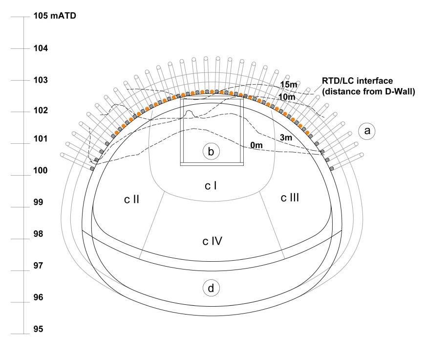
Figure 6: AP9 tunnel cross section at Moorgate opening showing pipe arch 1 including infill pipes (a), pilot Timber Heading (b), Top Heading Enlargement with pocket excavation (c I to c IV), and final full length invert (d) against the predicted RTD/LC interface at 0 m, 3 m, 10 m and 15 m distance from the D-Wall (see sections in Figure 4).
2) For breakout from the Box and mining under the initial pipe canopy the intended SCL pilot tunnel was amended to a pilot constructed using a small timber heading. This timber pilot tunnel was situated directly under the pipe canopy in the crown of AP9. The timber heading was adopted as it provides safer working environment if water or flowing ground is encountered. It also provides a much more rapid means of sealing up the tunnel and subsequently treating the ground in that circumstance. Additional pipes were provided in the first canopy because of the uncertainty as to the seal between the grouted ground and the Dwall at the breakout. After the timber heading the mining sequence consisted of enlargement to a top heading by pocket excavation to close to the end of the timber heading, as shown in Figure 6. Additional small probe holes were drilled within the timber heading to check the ground conditions and the presence of ground water ahead of the excavation.
3) Given all the concerns about the possibility of encountering groundwater in the treated ground, a depressurisation system was designed and installed before the opening of the AP9 eye. A series of inclined wells were installed around the eye of AP9 and around the treatment zone, with the aim of intercepting the RTD/LC contact and collect any residual groundwater within the treated ground. These well-points acted mainly as gravitational wells, but were additionally connected to a vacuum system to achieve better results. Initial flows of 60 to 15 l/min were obtained after the installation of the wells, and this dropped to circa 1 l/min during the following weeks.
Encountered Conditions
The Timber Heading confirmed the eventual success of the ground treatment and confirmed the presence of the rising channelled interface between London Clay and River Terrace Deposits in the crown (Figure 6). This knowledge allowed a reversion to a top heading and bench approach without a timber heading under the second and third pipe canopies.
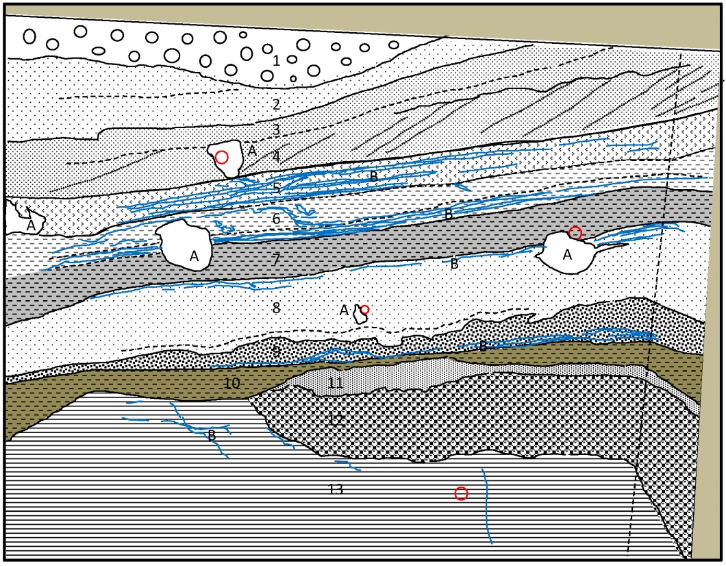
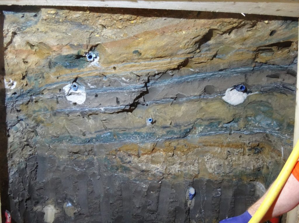
Figure 7 shows the geology encountered during the excavation of one of the timber heading frames, with the London Clay Formation at the base of the face and complex base of Taplow Formation towards the top.
The heterogeneity of the DFH infill was confirmed, with a mixture of granular sediments of variable grain sizes inter-bedded in clay and silt strata, which became predominant towards the base of the RTD. Grout had permeated well into the granular layers and fractured the less permeable silty and clayey bands, as shown by the sub-horizontal grout in-filled fractures.
The heterogeneity of the deposits in this small volume of ground in and around the crown of AP9 clearly hindered the grouting process and was the main cause of the subsequent changes to the tunnelling strategy.
Cross bedding in medium to coarse sand was observed within one of the strata (see Figure 7 and the description of number 4) suggesting a medium flowing environment during its sedimentation, most probably in a small channel. Some erosional contacts also suggest brief more energetic depositional environments, such the base of layer 1 in Figure 7.
The crown remained stable and dry in the pocket excavation as well as in the timber heading. There were localised minor seepages around some of the canopy pipes and a few minor face falls at the end of pipe arch 2, where the space between the flared pipes was wider.
Grout in-filled fractures were commonly present at the interface between the London Clay and the River Terrace Deposits Formation. These had a general sub-horizontal orientation, following the stratification of the London Clay, but occasional sub-vertical and inclined grout in-filled millimetric to centimetric fissures, which penetrated clearly into the London Clay. No other significant vertical grout filled discontinuities were seen. The route by which displaced ‘grouty’ water travelled to the Northern Line tunnels remains unknown.
The number of wedge failures or “greasy backs” was normal for excavation within the upper part of the London Clay (Unit A3 [10]). Various bands of claystones were intercepted along ES3 as shown in Figure 3, and these were possibly inclined slightly towards the South East as was the London Clay / Lambeth Group interface. No major jumps or sudden changes in the level of the claystone bands were noticed, indicating a lack of faulting in this tunnel.
The unexpected inward movement of the eastern wall of Moorgate Box is mostly likely to have resulted from clay found between the ends of the strutting Dwall panels and the external permanent Dwall panels. The presence of this clay is likely to have significantly reduced the stiffness of the strutting effect. Whether or not the grouting helped push the wall inwards remains unclear.
No significant ground movements were generated by the tunnelling.
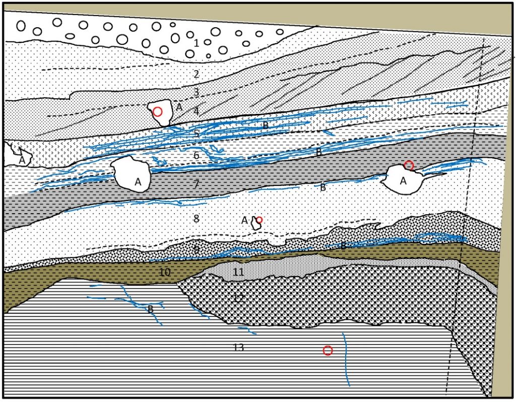
Approximate scale 1.5 *1.5 m. Legend: A. Weak to very weak cementitious grout filling voids around the TaMs; B. Veins of white and blue and grey grout; 1. Partially grouted very dense yellowish to reddish brown very sandy, very cobbley sub-angular coarse GRAVEL of light brown to reddish brown chert. Matrix comprises clayey coarse sand and lower contact is scoured and eroded; 2.Well grouted very dense light brown to bluish grey slightly coarse gravelly medium to coarse SAND. Gravel of light brown to reddish brown sub-angular chert. Layer is thinly bedded, lower contact is sharp and straight; 3. Partially grouted or weakly cemented, yellowish to reddish brown, fine gravelly, medium to coarse SAND. The lower contact partially comprises yellowish brown very sandy medium to coarse GRAVEL. The lower contact is graded over 1-3 cm; 4. Partly well grouted, partly poorly grouted fine gravelly medium to coarse SAND. Layer is very thinly to thinly crossbedded with varying degrees of grouting. The lower contact is sharp and straight; 5. Firm yellowish brown slightly sandy clayey SILT with extremely closely to closely spaced grout filled fissures. Grout comprises bluish to white veins. Silt is otherwise not grouted. The lower contact is sharp and straight; 6. Stiff to very stiff medium grey slightly sandy, slightly silty CLAY with clay filled fissures penetrating downwards from the silt above and extremely closely spaced grout filled fissures in the lower 5 cm in more sandy CLAY. Clay is otherwise not grouted. The lower contact is straight; 7. None grouted stiff to very stiff medium grey CLAY; 8. Partly grouted or weakly cemented, very dense yellowish brown to medium grey fine to medium SAND. The upper 2 – 5 cm are fractured by grout filled fissures. The lower contact is undulating and irregular due to the gravelly nature of the layer below; 9. Very well grouted very dense dark grey coarse gravelly medium to coarse SAND with occasional cobbles. Gravels of well-rounded weak yellow brown to red brown claystone and sub-rounded to sub-angular brown chert. Lower contact is sharp and straight. The claystone clasts are likely rip up clasts from layers 10 and 11. 9 and 8 are likely the same stratigraphic layer grading up from gravelly coarse SAND at the base to fine SAND at the top. Pervasive grout fissures separate the gravel from the clay layer below; 10. None grouted stiff to very stiff medium brown CLAY; 11. None grouted to partially grouted fine sandy CLAY to clayey fine SAND. Lower contact is irregular in contact with the gravel layer below; 12. Partially grouted, very dense light brown clayey, sandy cobbley coarse GRAVEL; 13. Stiff to very stiff brownish grey CLAY (London Clay Fm) Figure 7 – Details of the geology seen in part of the timber heading
Conclusions
- Ground conditions at the point of breakout from Moorgate Box were gradually revealed to be extremely challenging for an SCL tunnel from both a safety and an asset protection viewpoint.
- An iterative process of ground model revision and evolving construction risk management successfully delivered a robust temporary works sequence for the tunnelling.
- Data relevant to the ground model was gathered and reviewed at every opportunity, including data from neighbouring contracts.
- An important part of this iterative process was close collaboration between the Contractors, the Designers and Crossrail’s Delivery and technical engineering support organisations.
- The tunnelling was completed safely and with minimal ground movement.
Geological observations
The following table summarises the characteristics of the Moorgate DFH in relation to the generalised characteristics given by Banks et al 2015[11]:
Table 2: Characteristics of Moorgate DFH based on Banks et al (2015) [11]
Common DFHs characteristics described by Banks, based on Hutchinson [2 and 3] Moorgate DFH Buried hollows type (1) underlain by London Clay, (2) with roots penetrating deep into the basement below the London Clay. (1) Underlain by London Clay Formation Underlying strata uplift – evidence of faulting (and associated Lambeth Group sand channels) No significant evidence of either at the Moorgate site, though Lambeth Group sand channels were seen nearby. Affinity with Kempton Park Gravel Located at the back edge of the higher Taplow Formation Terrace floodplain Large scale ground deformations None identified Associated with the Holocene river network Close to the possible courses of Walbrook tributaries Ongoing work by the first named author and others is developing a classification of DFHs based on evidence of disturbance, either under the DFH or of the infilling materials. Most medium to large scale DFHs show evidence of some disturbance. This classification arises from the speculation set out earlier that these features begin as fluvial scours in high flow, high energy river systems in the waning and warming end phases of periglacial cold spells. If these scours become deep enough they can suffer basal failures caused by high artesian pressures in the lower aquifer. A process that may be repeated in subsequent cold spells as the DFH contents are refrozen and fail again during warming.
The Moorgate DFH is unusual for it size in that the infilling shows no evidence of disturbance or high energies. The London Clay in the base of the DFH did not exhibit any feature that might indicate uplift, disturbance or water flow. The interbedded materials with small scale sinuous channels found at the lip of the DFH by the tunnelling suggest a late phase lower energy infilling environment.
Even though no larger scale faulting had been expected or encountered at Moorgate, indications of some small scale faulting were noticed during the excavation of other nearby SCL tunnels:
- A minor normal fault, of maximum 0.5 m throw affecting the London Clay / Lambeth Group (LC/LG) contact, was recorded during the mining of Ventilation Duct 5 (VD5) tunnel, which is located at the North West corner of Moorgate Shaft and connects the box with the eastbound TBM launching chamber.
- Further irregularities in the LC/LG contact were also noticed in the westbound TBM launch chamber (LCWa) at the south west corner of Moorgate Box. Here the London Clay Lambeth Group contact clearly dip towards the south across the face, and a rise in level of ~0.5 m occurred in the first part of the excavation, in line, approximately, with the normal fault observed in VD5 tunnel.
- No geological faulting was observed during the excavation of the westbound platform tunnel. However the combination of a westward rise of up to ~2.4 m in localised steps (~1.2 m) of the London Clay basal contact and the near uniform thickness of the underlying Upper Mottled Beds may be indicative of distributed deformation due to folding or faulting over a wider area.
- To the east a water-bearing sand channel was present within the top of the Lambeth Group in the westbound tunnel and this continued across the Concourse tunnel and the eastbound tunnel in a northwest to southeast alignment. Furthermore, another extensive water-bearing sand channel (>10 m lateral extension) was identified within the laminated beds along the eastbound tunnel and in Ventilation Duct 4 tunnel, which also links to the northwest corner of Moorgate box. Continuous depressurisation was required during the excavation of these tunnels, suggesting a nearby source of recharge.
Acknowledgements
The successful completion of Moorgate Box and AP9/CH6 tunnel within the Moorgate DHF has been possible thanks to the contributions of many people involved in the project especially miners, drillers and engineers. We would like to acknowledge the client Crossrail, the designers Morgan Sindall Underground Professional Services, BeMo Tunnelling and Mott Macdonald; and the main contractor BBMV JV (Balfour Beatty, BeMo Tunnelling, Morgan Sindall, VINCI construction).
-
Authors

John Davis EurGeol CGeol MSc DIC - Geotechnical Consulting Group
John was seconded to the Chief Engineers Group within Crossrail from Geotechnical Consulting Group LLP from 2009 until July 2016.
Within the Chief Engineers Group John was responsible for all Crossrail geotechnical matters east of Farringdon. Whilst at Crossrail John was also closely involved with the production of Geotechnical Baseline Reports for all the major Civils contracts. Prior to Crossrail John spent 20+ years as a geotechnical designer working on a diverse range of structures across the world, these included deep basements, embankments, tunnels, slopes and retaining walls. John was seconded to London Underground for a couple of years in the mid 90’s where he led a research programme on the impact of rising groundwater on the tube network.


Dr Alfred Stärk Dipl Ing Dr Ing - BeMo Tunnelling
Dr Alfred Stärk is Chief Geotechnical Engineer and Engineering Manager at BBMV for Crossrail Contract 510 ‘Whitechapel and Liverpool Street Station Tunnels’ since March of 2011. He started his career at the University of Hanover, Germany, where he worked as assistant professor and consultant for 10 years. In 2002 he joined BeMo Tunnelling, Innsbruck, Austria. He now has 25 years of experience in large-scale tunnelling, mainly with sprayed concrete lining in soft ground.