Use of Non-Metallic Materials in Ventilation Airways- a review of aerodynamic performance and material requirements
Document
type: Technical Paper
Author:
Wing Fung PhD MSc BSc(Eng) CEng MCIBSE, Harry Shone, Allister Ash, ICE Publishing
Publication
Date: 30/09/2017
-
Read the full document
1. Introduction
A number of built enclosures in Crossrail stations, shafts and portals are used for ventilation purpose. They are in the form of blockwork wall, spray concrete lining structure or reinforced concrete panels in plenums or airducts. These enclosures are referred to as ‘airways’ in this paper.
While they could be used in principle to provide conduits for passage of air, there are technical considerations that have be overcome before they are fit for use. Crossrail material and workmanship specifications for ducts and plenums are primarily based on sheet metal ductwork construction. Industry design and construction codes like DW144[1] are also written only for sheet metal air ducts.
This paper describes how Crossrail tackle the technical challenge to allow the use of these airways to function effectively as an integral part of the ventilation system. Some of key challenges are:- Integrity of the airway structure against the design pressure force (which is not normally designed to take lateral loads).
- Air leakage because of the pressure differential between the enclosure and the surrounding and sealing of joints between the airways and other horizontal and vertical structures.
- Surface roughness and change in cross sections if the enclosure is used as an airway.
- Maintenance inspection and future replacement requirements throughout the asset life cycle.
These types of airway can be found in firemen staircase, lift shaft and lobby fitted with pressure differential system, intake and exhaust plenum and air duct of UPS, intake and exhaust plenum of Platform Smoke Extraction, exhaust plenum for TVS, room or plenum fitted with gas fire suppression system and air ducts and plenums where DW144 does not apply.
2. Performance Requirements
2.1 Operating Condition
Ventilation designers should first of all ascertain the design operating conditions of the airway. These parameters include, but not limited to, temperature and relative humidity, air velocity, contaminants in the air stream, working air pressure differential and maximum transient air pressure differential.
2.2 Structural Integrity
A design check of the integrity of the enclosure should be carried out in respect of the likely pressure difference between the enclosure and the surrounding. Failure to address this issue may result in cracks, dislocation and loosening of components of the airway and, in extreme cases, collapse of airways during the commissioning or revenue operation stage when the extreme pressure fluctuations happen. Consequences include injuries, costly line wide inspection and repairs and major service disruptions.
In the event that the airway is alongside the train running tunnel and that the structural enclosure of the airway is not designed for the purpose, the integrity of the components within the platform smoke extract plenum (sealants, joints and connections) has to be tested against anticipated cyclic pressure fluctuations due to train operations (notably the piston effect), operation of the Tunnel Ventilation System (TVS) as well as the platform smoke extraction fans. The pressure tests are specified to ensure the components can withstand the predicted worst case tunnel pressure fluctuation scenarios.2.3 Air Leakage
An analysis should be carried out to predict the leakage rate from the airway under the design operating condition. Potential air leakage paths are building material for the enclosure, construction Joints, movement joints and inspection/ maintenance hatch doors. Excessive plenum leakage will render the plenum inefficient or ineffective as a ventilation airway. Consequences include costly line wide repair and delays in revenue opening as this is unlikely to be discovered until a later stage of commissioning. The predicted leakage rate shall not exceed the maximum air leakage rate as determined by the following equation:
Aggregate air leakage (litres per second per square metre of duct surface area) ≤ 0.009 x P0.65
The leakage rate should be reflected in the fan sizing and selection. Air leakage testing shall be carried out in accordance with DW/143[2]: A practical guide to Ductwork Leakage Testing.
Airways constructed adjacent alongside the train running tunnel will be subjected to air pressure fluctuations due to train piston effect and the operation of TVS/ Platform smoke extraction fans. An assessment of the likely tunnel pressures under normal operating conditions and in a perturbed mode. In Crossrail, a smoke extraction plenum is installed in the station tunnel above the track to the length of the platform as an airway to extract platform smoke. At least one side of the plenum wall will be exposed to the tunnel pressure. Pressure tests are carried out to demonstrate that the air leakage levels within the platform smoke extract plenum are within acceptable limits when the plenum is operating at the working pressures and that air leakage levels will not jeopardise the performance of the smoke extract system.Section 5 of this paper provides more details of field tests that were carried out in Crossrail to determine the leakage level in the air plenum structure above the running tunnel.
2.4 Control of Contaminants
A health and safety impact assessment on potential threats arising from leakages from the plenums/ air ducts should be carried out. The findings are recorded in the HAZID register and mitigation measures established.
2.5 Sealant
Suitable sealant should be used in all longitudinal seams and cross joints as appropriate to minimise plenum/ duct leakages. The materials used should be suitable for the purpose intended and the design work environment as well as satisfy the specified pressure classification.
2.6 Surface Roughness
The degree of roughness of the inner side of the airway will very much affect the performance of the ventilation system and the life cycle operation cost. In most airways, with the exception of spray concrete lining structure, a fair face finish is achieved. This finish shall be obtained from formworks designed to produce a hard smooth surface with true, clean arrises. Only very minor surface blemishes shall be permitted. Any projections shall be removed and the surface made good. The surface finish is consistent with Types B in Clause 6.2.7.3 of BS 8110: Part 1[3]. Similar degree of roughness shall be achieved for airways constructed of other building materials apart from blockwork/ concrete. Smooth transitions between sections of the airway are also maintained.
A technical study is carried out to confirm that the use of spray concrete lining in the platform smoke extraction plenum in Crossrail stations will not impair the performance of the airway by virtue of its rough surface finish. Section 3 of this paper describes how field measurements were made to determine the degree of roughness and the correlation of the measured data with predicted airway pressure loss.
2.7 Pressure Loss Calculations
All changes in shapes, expansions and contractions must be allowed for in the airway pressure loss calculations. Where a change shape is necessary to accommodate the duct and the cross-sectional area is to be maintained, the slope does not exceed 22½° on any side. Where a change in shape includes a local reduction in duct cross-sectional area, the slope does not exceed 15° on any side and the reduction in area should not exceed 20 per cent. Where these are required, an expansion shall be made upstream of a branch connection and a contraction downstream of a branch connection. The slope of either an expansion or a contraction should not exceed 22½° on any side. Where this angle is not practicable, the slope may be increased, providing that splitters are positioned to bisect the angle between any side and the centre line of the airway.
Many of the airways in Crossrail are of irregular shape. Section 4 of this paper provides detail analysis of the impact of an irregular shape airway on pressure loss calculation.2.8 Acoustic/ Thermal Insulation
An assessment is carried out to determine whether internal/ external thermal and/or acoustic insulation is needed.
2.9 Inspection/Servicing/Cleaning Access Openings
The size and location of the access openings are appropriate to allow periodic cleaning and inspection.
3. Measurement of Surface Roughness and Pressure Drop Calculations
Most airways constructed of smooth surface and do not impose high resistance to air flow. However there is an exception in over track air extract plenum in Crossrail platforms. Part of plenum surface is made of spray concrete lining (SCL). The surface roughness of the secondary lining within the bored platform smoke extract plenums has a significant influence on the pressure loss calculations for the smoke extract system. In this connection, the correlation between surface roughness and the pressure loss has to be determined.
The surface roughness parameter is necessary to achieve an approximate calculation of the pressure drop throughout the platform smoke extract plenum. This issue has arisen because the surface roughness of SCL is an unknown factor that has been shown to greatly affect the pressure loss through the station plenums. More clarity is needed on the equivalent surface roughness of sprayed concrete. There is a need to calculate the pressure drop through the stations smoke extract plenums which utilise the SCL wall as a bounded surface.
A smoke extract plenum is located within the majority of platform tunnels and is comprised of differing materials; SCL (regulating layer), concrete soffit and laminated steel. The concrete soffit and laminated steel are used to enclose a space bounded by the SCL wall for use as a smoke extract plenum. In order to calculate the pressure drop along the plenum it is necessary to know the surface roughness of each material. In the reference design, surface roughness parameters in Table 4.1 of CIBSE C are used in the analytical study of the pressure loss along the plenum. In developing the ventilation design further, there are concerns over the use of correct surface roughness figures for the particular kind of SCL used in Crossrail as there is no standards exist for the surface roughness of SCL. The values employed were based on assumptions for the properties of the wall lining. Through discussions within CRL it has been highlighted that the final layer of sprayed lining will be the fire regulating layer. This uses an aggregate of between 2- 6mm. Given that k values are based on the average height of the surface imperfections per millimetre (Peaks and troughs) it follows that an average variance of 500mm is very large. CIBSE C[4] states the use of 500-1500 k/mm for rock tunnels that are roughly cut and highly uneven. SCL surface finishes do not fall within this category. The method statement on applying SCL surface finish stipulates the maximum allowable surface roughness of the primary lining so that the waterproofing membrane is properly adhered when applied. A surface roughness of 15mm (maximum local height deviation) was the limit of acceptance. The surface roughness was assessed using a comb test method.
Figure 1 shows the roughness testing comb that reproduces the localised surface finish. A graphical representation can then be created that is used to determine the local equivalent surface roughness. An example of a very good surface finish can be seen in Figure 2, with the graphical representation of this shown in Figure 3. This test is conducted on the plenum chamber SCL surface to allow for an accurate determination of the local surface roughness.
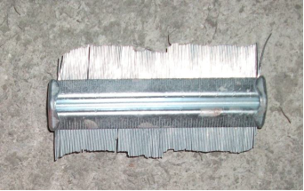
Figure 1- Roughness testing comb

Figure 2 – Examples of acceptable surface roughness, with maximum surface
roughness features in the order of approximately 5mm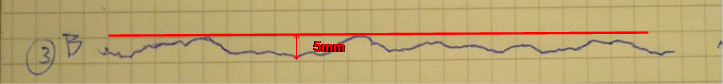
Figure 3 – Comb test results for the surface roughness of the regulating layer
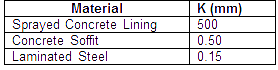
as shown in Figure 1The following equivalent surface roughness values k (mm) are used in the technical study;
3.1 Surface Profile
The surface finish of SCL is the primary concern when considering the surface roughness. However, the wider variation caused by SCL thickness must also be considered. The variation in SCL thickness could amount to much larger instantaneous variations in the surface profile and hence increase the equivalent surface roughness. Figure 4 shows the SCL profile measured in one of the Crossrail work sites. It details the thickness variation of the applied concrete layer with the maximum permissible variation of 150mm before rework is required. Rework would either be that more material was required, or that material needs to be removed and reapplied to ensure the profile is within the acceptable limits. An instantaneous variation of 150mm is extremely unlikely but possible and could be stated as the worst case scenario.
It is concluded in the technical study that the variance in surface profile is unlikely to have a significant performance impact on air flow in the smoke extract plenum.
Figure 4 – SCL Profile
3.2 Pressure Drop Calculation
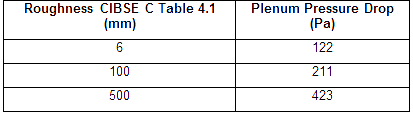
The calculation methods used in the ventilation design for the pressure drop are industry standard and will provide a close approximation of the losses that would be expected throughout the plenum, given that an appropriate surface roughness is used. A high surface roughness factor used in a conservative design will result in an excessive pressure loss and therefore a high fan power and vice versa. In a typical smoke extract design in Crossrail, the plenum pressure drop is 423Pa over the entire 120m length if a roughness factor for the SCL of 500 mm is used. Whereas this pressure drop is significantly reduced to 122 Pa should the SCL roughness is 6 mm.
Given that the final fireproofing regulating layer employs a concrete mix design with a maximum aggregate size of 6mm it follows that surface variations of 500mm will not occur. The maximum surface roughness of 15mm that was required for the waterproof membrane application is more applicable. If the SCL profile is considered (See Figure 3) it can be shown that the absolute maximum surface height variation would be 150mm before rework is required and even this variation is unlikely. In the pressure drop calculation of the platform smoke extract plenum, it could be assumed that the roughness for the length of the plenum would be in the order of 5mm and certainly not exceeding 15 mm.
As a result of the analysis, Crossrail suggests to ventilation designers that a roughness of 15 mm should be used and that random site measurements of SCL surface roughness should be carried out to confirm the construction tolerance of surface roughness and surface profile.
4 Platform Smoke Extract Plenum- Hydraulic Diameter
In a ventilation design, predication of pressure loss is made either through solving the air flow equation on the basis of a circular air duct with an equivalent hydraulic diameter (empirical adjustment factors are applied in the event that non-circualr air ducts are used), or through the use of experimental technique (physical moddelling) or numerical simulation technique.
In Crossrail, many of the the airways are of irregular shape. A technical study was carried out to determine the most appropriate analytical tool to be used on pressure loss calculation using the platform smoke extract plenum at the bored platform stations as a test case.
The platform smoke extract plenum forms part of the station ventilation and smoke extraction systems and is located above the track over the length of each platform. Each plenum is sub-divided into 2 sections of approximate length of 120 m for each platform. Each half section of the plenum is connected to the smoke extract fan systems. The smoke extract fan systems are being designed to extract 10 m³/s of smoke in a platform fire situation. In order to correctly size the fans the pressure drop across the plenum must be calculated. The plenum itself is made up of a sprayed concrete lining section (SCL), a concrete base and corbel and a metal duct section, as seen in Figure 5.
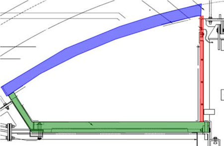
Figure 5 – Plenum Cross-section
The design of the plenum forms an irregular shape, which adds uncertainty to the calculation of pressure drop across the structure. In order to simplify the calculation the hydraulic diameter can be calculated. Essentially this is an approximation which converts the plenum shape into an equivalent circular shaped duct. During the ventilation design, there are concerns over the use of this design approach. There was concerned that simplifying the plenum geometry may not accurately model the actual air flow conditions, affecting the accuracy of the pressure drop calculation. In order to represent the exact geometery of the Plenum, it was suggested that numerical simulation using Computational Fluid Dynamics (CFD) may be more appropriate to study the flow characteristics in the plenum structure.
4.1 Governing Equations
As stated in CIBSE Guide Book C, Section 4.3.1; the D’Arcy equation for pressure loss due to friction maybe given as:
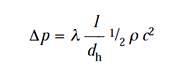
Equation (1)
The Friction factor, λ depends upon the Reynolds Number, Re and the Relative Roughness:
Equation (2)
where:
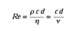
ρ = Density (kg/m3)
c = Velocity (m/s)
d = Diameter (m or mm)
η = Dynamic viscosity (kg m-1 s-1)
ν = Kinematic viscosity (m2/s)Relative Roughness= k/d
Equation (3)
where:
k = Equivalent Roughness (mm)
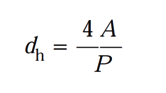
For ducts of non-circular cross section (CIBSE C, Section 4.8.8.1), the use of the D’Arcy Equation necessitates the use of a value for a ‘diameter’ characteristic of the non-circular duct. It has been shown that for this the hydraulic mean diameter is the most appropriate parameter, defined by:
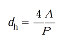
Equation (4)
where:
A is the cross-sectional area (m2)
P is the perimeter (m) of the ductThe pressure loss is then given by:
Equation (5)
To obtain a value of friction factor, λ, the Haaland equation can be used.
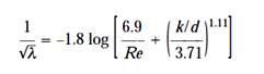
Equation (6)
For the hydraulic diameter dh should be used for obtaining the relative roughness k/d and Re. The use of Equation 5 then gives the pressure drop for any condition of air and duct material. The use of the Colebrook-White equation to calculate λ is also suitable.
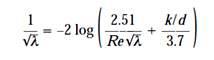
Equation (7)
The use of equation 7 returns values of λ which are 2-4% greater than other methods and as such can be considered to be conservative.
The point of uncertainty is whether hydraulic diameter, dh can be assumed for the irregular plenum geometry. CIBSE C, Section 4.8.8.1 states that hydraulic diameter may be used for ductwork of a non-circular cross section, provided that the duct shape does not consist of particularly sharp apex angles. In such a case it has been shown that the assumption is fundamentally flawed and the use of Equation 4 does not give a good correlation. This is because the flow in a circular duct is totally symmetrical about the axis, giving identical fluid velocities close to all parts of the duct surface; which is not the case within non-circular ducts.
However, examination of Figure 5 confirms that the geometry of the Plenum structure does not contain sharp apex angles and hence the standard practice of using hydraulic diameter to idealise a non-circular duct is acceptable.
4.2 Numerical Simulation
The benefits of undertaking a Computational Fluid Dynamics (CFD) study are considered to be minimal for this application. In order to obtain reliable result for subsequent design work (on pressure drop etc.), accurate information about the boundary conditions will be required. Such a study would require the roughness figure to be determined by test before commencement to be of any use. For confidence to be placed in the simulated boundary conditions, measured surface roughness data is required. This also holds true for the value of relative roughness used to calculate friction factor, λ, within Equations 6 and 7. Depending on the CFD software used in the simulation, pressure drop results may also requires validation through the use of physical modelling which can be time consuming and costly. On the basis of the above, CFD is not considered to be appropriate analytical tool for pressure loss calculations for airways.
5 Air Leakage Tests
This Section describes how air leakage test is carried out for the platform smoke plenum in a typical Crossrail station. The testing requirement differs from one work site to another depending on such factors as operating pressure, airway configuration.
In this test, the platform smoke plenum is of modular design, i.e. it is made up of repetitive modules consisting of extract air openings, maintenance hatches and connection joints. To provide evidence of conformance to performance requirements, the leakage tests are carried out on representative sections of the plenum, and if successful, it can be deduced that the results can apply to all remaining sections of the plenum (made up of typical modules). This is on the basis that a quality management system is in place to ensure consistency in workmanship throughout the entire platform smoke extract plenum length.
As a minimum, pressure tests must be completed on a typical section/module of plenum. This section must be on a representative stretch of plenum that includes all ‘typical features’; i.e. an extract opening, plenum joints and a maintenance access hatch. The length of plenum tested will entirely depend upon the placement of these features. For each of these sections, both integrity and leakage tests must be performed, meaning for each platform a total of 2 tests must be passed. It should be noted that any other sections of plenum that are deemed ‘non-typical’ may require further testing in addition to those mentioned. Sectional pressure tests upon the platform smoke extract plenum are carried out once a section of plenum is ready for pressure test. This is to avoid abortive work in the unlikely event that the tests fail to meet the performance requirements (See Figure 6).
The maximum acceptable leakage rate is 5% of the working volume flow rate as a proportion of the test length over the plenum length. In the event that the test fails to meet this requirement, a work plan should be submitted to the Project Manager outlining remedial works to identify the location of leakages and means of rectification. Leakage tests shall continue until the acceptable leakage rate is achieved. Leakages that are only marginally above the acceptable rate will be tolerated if the total leakage rate based on the accepted test results for the smoke plenum can be accounted for in the specified extract fan duty.
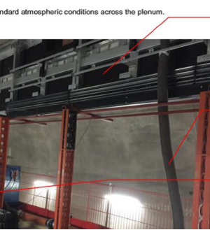
Desktop analysis of testing results is carried out to determine the projected total leakage rate based on extrapolated test results from the typical section.The tests were carried out at a normal room temperature for both positive and negative pressure scenarios. The tests comprised of measurements of the rate of air leakage through a measured section of ductwork by application of a series of test air pressure differentials across the specimen with measurement of the air leakage of it at each pressure step. The maximum positive and negative pressure differential was -1000 Pa /+1 100 Pa (or the design working pressure plus safety margin). Details of tests carried out the airtightness test was carried out using a powerful fan to de-pressurise and pressurise the shaft it was set up in a ply template fixed to an access panel in the shaft with the reference tubes placed in the plenum through another access panel near the centre of the section to be tested. (See figure 7).
The barometric pressure, internal and external temperatures were also measured and recorded before and after the test. With the test set up complete and fans temporarily covered, zero flow pressure readings were then measured and recorded. The fan was operated to blow air into the plenum and a series of measurements of air flow rates and corresponding indoor/outdoor pressure difference over a range of fan flows are taken. Indoor pressure readings were recorded using terminals placed in an approximate geometric centre of the duct under test with the external to the tunnel platform. Once a suitable reference pressure was achieved the flow of air through the fan was measured and recorded. The speed of the fan was then maintained for 15 minutes so the plenum was under constant pressure and the data is recorded again (See Figure 8 and 9). This process is repeated for up to three sets of data. The values of the mean internal and external temperatures and the barometric pressure were used to correct the flow rate through the fan to standard atmospheric conditions.
Figure 6 – Five separate sections of the plenum tested
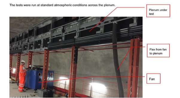
Figure 7 – The tunnel plenum being tested on the station platform
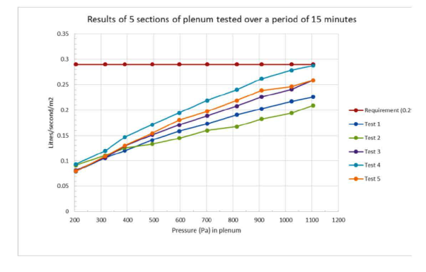
Figure 8 – Air leakage under positive and negative air pressure
(maintained for 15 minutes for each area tested) – Test section 1 – 5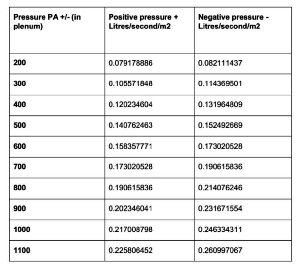
Figure 9 – Air leakage under positive and negative air pressure
(maintained for 15 minutes) – Test 1References
[1] DW/l44, Specification for Sheet Metal Ductwork Low, medium and high pressure/velocity air systems, Heating and Ventilating Contractors’ Association, 1998
[2] DW/143, Guide to Good Practice Ductwork Air Leakage Testing, Sixth Edition, Building & Engineering Services Association, 2013
[3] BS 8110-1:1997, Structural use of concrete — Part 1: Code of practice for design and construction, BSI, 2007
[4] CIBSE Guide C: Reference Data, The Chartered Institution of Building Services Engineers London, 2007 -
Authors

Wing Fung PhD MSc BSc(Eng) CEng MCIBSE - Arcadis
Technical Director (MEP), Arcadis
Wing is is a Chartered Engineer with over 30 years’ experience as a technical specialist engaged in mass transit system planning, design, project management, technical assurance, commissioning, energy management, operation and maintenance, and asset renewal. Wing has been with the Crossrail project in the CRL Chief Engineer Group since 2013, overseeing mechanical design, systems integration and T&C.
Specialties: Building Services, Mechanical Engineering, Computational Fluid Dynamics, RAM studies, Systems Integration, Requirement Management, Testing and Commissioning.

Harry Shone - Crossrail Ltd
Mechanical Engineer
Allister Ash
Former Field MEP Engineer, Crossrail