Vibration Management and Listed Buildings
Document
type: Case Study
Author:
Andrew Bird BSc (Hons) MIOA, Colin Cobbing BSc(Hons), CEnvH, MCIEH, MIOA, David Keeley, Suzanne Bryon BSc (Hons) AIEMA, Graham Aubrey, Kenneth Hills, Richard Holbrook, Rick Methold
Publication
Date: 26/02/2016
-
Read the full document
Background
MacMillan House
Listed buildings account for 2% of the building stock in England [1] and of those listed buildings, only 2.5% are Grade I listed [2]. Paddington Station, which includes MacMillan House, is Grade I listed because of its historical and architectural importance during the birth and early development of rail transportation in Britain.
Paddington Station was planned and designed by I K Brunel in collaboration with Matthew Digby Wyatt and was built between 1851-4 by Fox Henderson and Co. The 1854 station buildings comprised a triple span shed flanked on its south (Departures Road) side by a two storey building housing the offices of the Great Western Railway Company. This building is now known as Macmillan House and has a central element with an open, ground floor, seven-bay entrance arcade (The Clock Arch) fronting to Departures Road.
MacMillan House extends along almost the full length of Eastbourne Terrace and Departures Road. The structure’s original walls are predominately of brick and of mostly 4 storeys with a basement. Floors are a mixture of brick arch and concrete beam, sometimes hollow, and riveted girders. For descriptive purposes the building is divided into several blocks each approximating to individual phases in its development (Fig. 1).
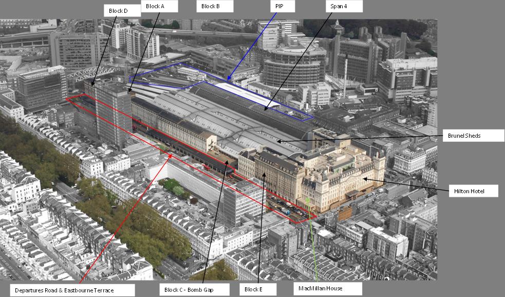
Figure 1 – Site location plan
In summary:
• 1851-1854; Blocks B and D. These represent the original extent of buildings.
• 1878-1881; Block A inserted as a link between Blocks B and D,
• 1880; Block E (adjacent to Bomb Gap), known as the Digby Wyatt building,
• 1931-1936 Block E (adjacent to hotel) added in two separate phases
• 1958 Block C, the Bomb Gap.
Schedule 9 to the Crossrail Act 2008 disapplies section 7 of the Planning (Listed Building and Conservation Areas) Act 1990 for certain works to some listed building, in relation to the construction of the railway . However, in order to give some details of the works to the Local Planning Authorities, the Secretary of State for Transport required the Nominated Undertaker (Crossrail Ltd ) to sign Heritage Deeds with Local Planning Authorities (the City of Westminster in this case) and The Historic Buildings and Monuments Commission for England (previously known as English Heritage now Historic England). These Heritage Deeds require details of how specific works affecting listed buildings will be carried out to be approved by the Local Planning Authority.
As set out in each Deed, when the building is grade I or II*, Crossrail Ltd is also to consult with Historic England and the specified National Amenity Societies which comprise The Ancient Monuments Society, the Victorian Society and the Twentieth Century Society.
Condition Survey
A condition survey of the heritage assets was undertaken before commencing works and elements vulnerable to vibration damage were identified. The condition survey of the internal and external building fabric was carried out by visual inspection and analysis. The survey concentrated on the building facades and internal rooms within close proximity of the works anticipated to generate high levels of vibration.
The scope of the condition survey was determined based on analysis of preliminary vibration data measured on the external plinth of the historic and internally on the basement wall facing the vibration source. This initial analysis identified a requirement to focus the condition survey on inherently weaker building fabric such as, hair reinforced plaster ceilings and wall plaster.
The survey was carried out by a specialist historic buildings consultant who is formally accredited in building conservation. Decisions were made based on available evidence and judgement based on experience.On the Paxton Canopy, elements which were considered vulnerable to vibration included the glass roof and timber glazing beads which retain the glass.
Internally, MacMillan House was found to be generally in good decorative order with a moderate amount of modern intervention and repair. Most of the original wall plaster remained in place, with patch repair and replacement in modern gypsum plaster. In most areas the original plaster ceilings were concealed behind modern suspended tile grid ceilings.
Where the ceilings were visible, fine cracking was evident. No displacement or misalignment of the plaster surfaces was evident which would indicate a loss of adhesion to the background or a failure of the timber lath support.
The survey included the basement structures which project beyond the main façade of MacMillan House (Blocks A and B) below the pedestrian footpath towards the Crossrail construction site. The basements are approximately 5m from the northern diaphragm wall. The basement structures were found to be constructed from mass brick walls with a concrete roof (the beer cellar access was covered with steel doors) and plastered internally, with the exception of the beer cellar access with modern gypsum plaster. These structures were considered to be generally very robust by the heritage specialist.
Access to the historic plaster ceilings was limited and full condition survey would have incurred considerable costs. To minimise risk, the condition survey focused on visual assessment with limited physical assessment where access permitted. Physical assessment was carried out by pressing the ceiling soffit by hand to assess deflection, strength and adhesion of the plaster to the lath and structural background.
Description of Station Construction Works
The Crossrail project will see Paddington Station undergo one of the most significant transformations since it was first built. The Crossrail Paddington Station is one of the largest ticket halls on the Crossrail route, taking the form of an underground box approximately 260m long, 25m wide and 23m deep, and located directly under Departures Road and Eastbourne Terrace.
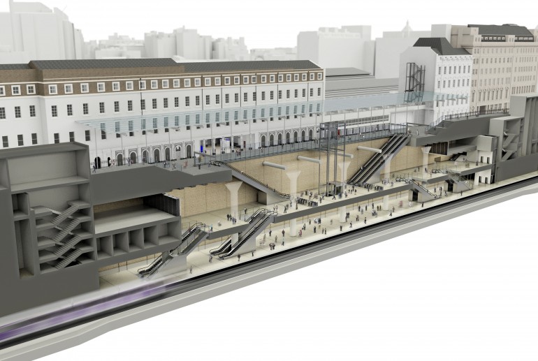
Figure 2 – Artist Impression of the new Crossrail Paddington Station
The Costain Skanska Joint Venture (CSJV) is the contractor completing the works, a significant undertaking which requires 250,000 cubic metres of excavation, 170,000 tonnes of concrete and 14,000 tonnes of reinforcement. Construction started in October 2011 and is due to be completed during 2017.
Work started in April 2012 to construct the 40 metre deep reinforced concrete walls around the perimeter of the new station. Crossrail, Costain Skanska JV and subcontractor Cementation Skanska worked around the clock for 11 months to put in place the diaphragm wall panels (as shown in figure 4). The completed walls have required over 64,000 tonnes of concrete and 5,000 tonnes of steel in their construction. The excavation of these panels saw over 53,000 tonnes of London clay removed.
Once the diaphragms walls were in the ground, the roof slab was cast on the top of the walls to form a 5 sided box. Access holes were left in the roof slab to allow muck to be removed from within the box as it was excavated down to full depth so that the base slab could be cast, sealing the 6 sided station box. This method is known as ‘top down construction’ and represents best practice for minimising noise impacts due to the self contained nature of the method.
At an early stage of the top down construction, the Tunnel Boring Machines (TBMs) passed through the bottom of the diaphragm walls to connect the railway into the new station. As the box was excavated down to its full depth, the rings left by the TBM had to be removed to allow preparation of the track bed to be installed and platforms and concourse areas to be built.
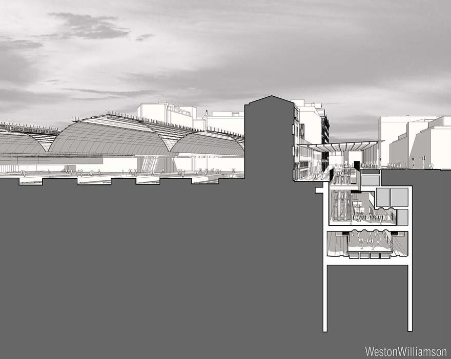
Figure 3 – Section through new Crossrail Paddington Station
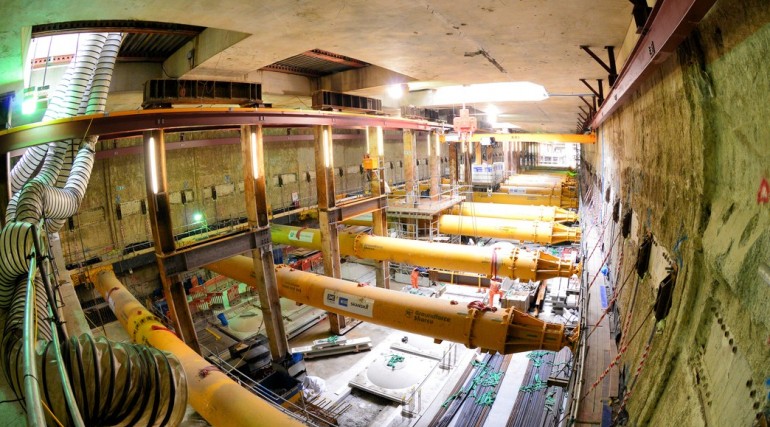
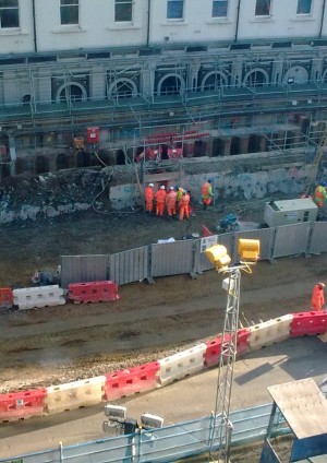
Figure 4 – Photograph inside the excavated Paddington Station showing Diaphragm Walls
Building Damage Risk Assessments and Monitoring Strategy
Given the proximity of the works to MacMillan House, (including the tunnels passing underneath), a significant amount of work went into assessing the risk of damage. The primary risk of damage was from settlement.
The risk assessments set out the monitoring requirements, which included 3 monitors to measure vibration, survey prisms and BRE levelling studs to measure ground movement (settlement) and crack width gauges on the existing cracks in the building to measure any change or movement.
As the works took place, the results from these monitors were then set to send alerts if pre agreed tolerances, established in the risk assessments, were exceeded.
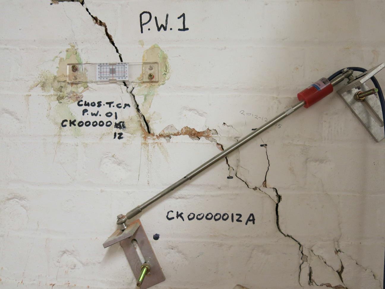
Figure 5 – Block E Crack Width Gauge
This case study does not deal with the effects and mitigation of settlement; however it is important to highlight that the amount of monitoring employed in this case study were not solely for the purpose of vibration controls and may not be suitable for or applicable to other projects.
The Diaphragm wall construction and reduction was identified as having the potential to generate significant levels of vibration at MacMillan House, being just 5-10m from the façade of the building.
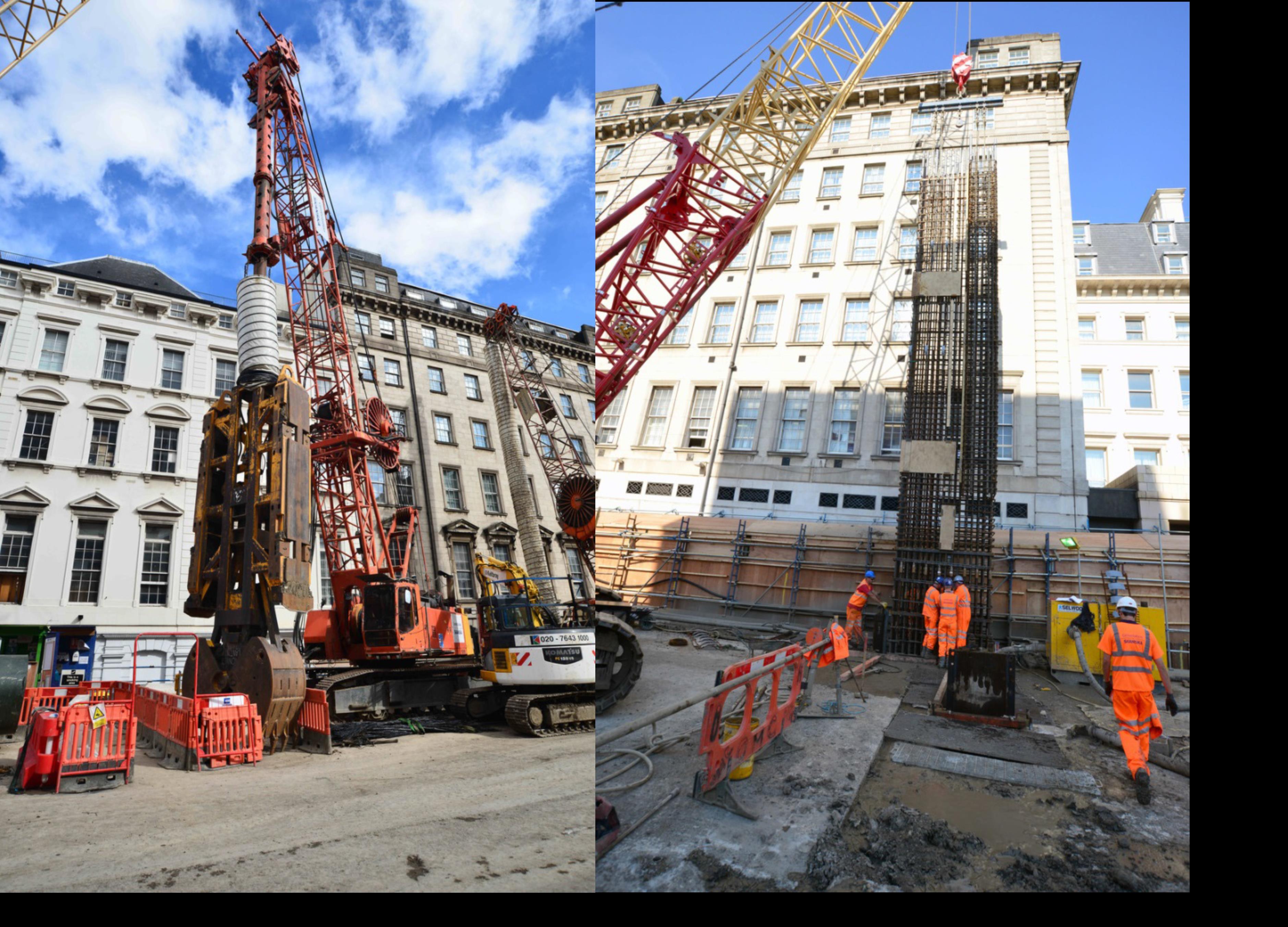
Diaphragm Wall Construction Method
Diaphragm walls are excavated and constructed in panels and slurry of bentonite is pumped into the trench as excavation proceeds to stabilise the side walls of the excavation to provide support and prevent the trench collapsing inwards. Once the trench is excavated to the correct depth, steel reinforcement is installed and concrete is pumped into the bottom of the trench displacing the bentonite, which is progressively pumped out of the trench and recycled as the concrete fills the panel.
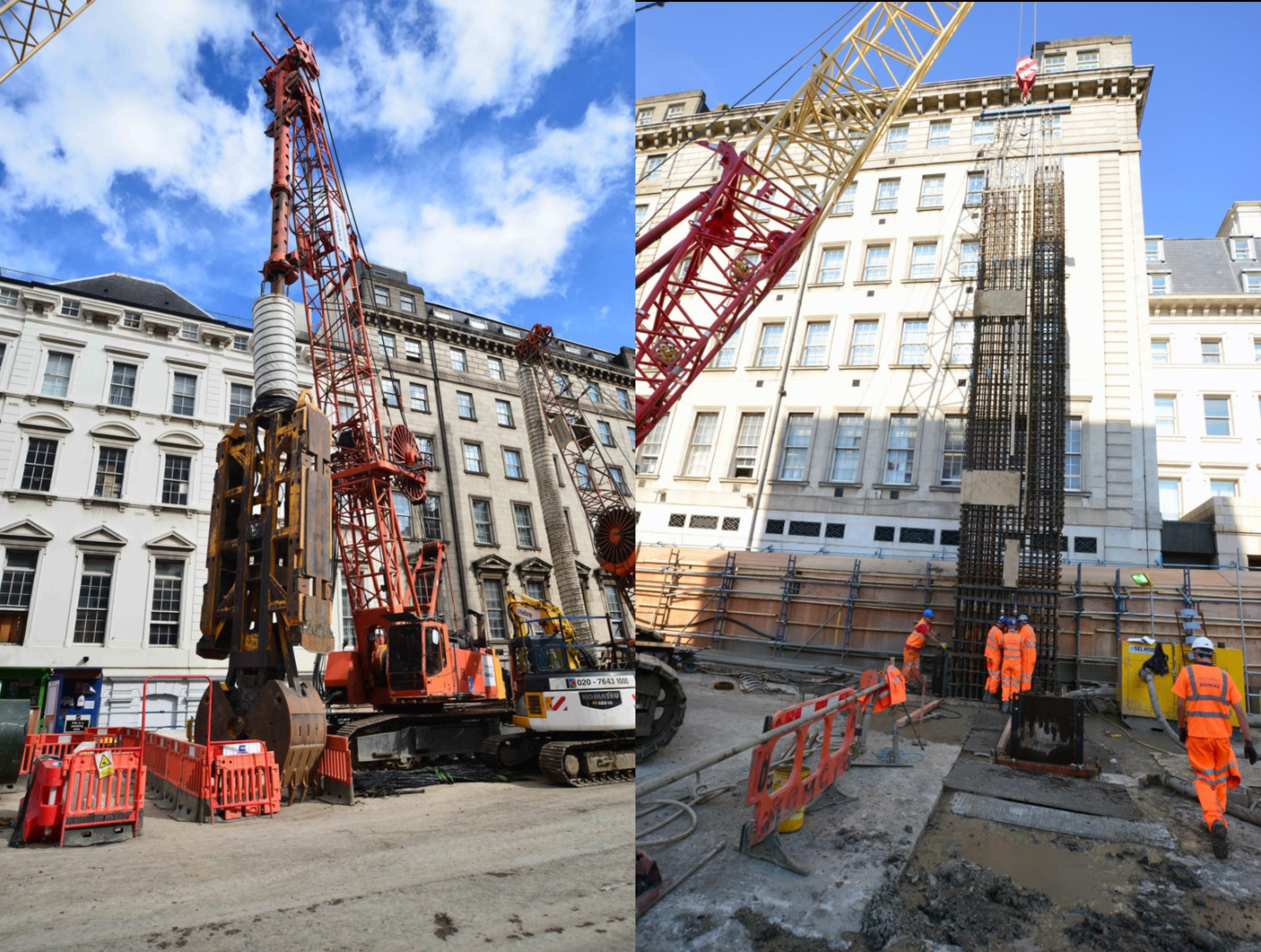
Figure 6 – Diaphragm Wall Construction (rig shown on the left and steel casing insertion shown on the right).
At the end of this process, a top layer containing a mix of bentonite and concrete is pushed up to the top of the diaphragm wall and forms a sacrificial top section between 2 and 5m tall that has to be removed at a later stage. The top section of the wall was also required for temporary support to the surrounding land prior to supporting sheet piles being installed at a later date.
Removing the sacrificial top section of the diaphragm walls posed the biggest risk in terms of vibration for 3 main reasons:
• Removing concrete requires significant force and is traditionally undertaken with heavy pneumatic equipment such as excavator mounted breakers which generate very high magnitudes of vibration with high magnitudes of low frequency content for sustained periods.
• The proximity of the wall, being within 5-10 metres of the façade of MacMillan House.
• The quantity/duration of works, given that the diaphragm wall spans the entire length of MacMillan House at 260m long, which equated to approximately 1200m3 of concrete to remove which took over 3 months to remove.Effects of vibration
Vibration and Building Damage
Vibration induced damage to buildings usually begins with the appearance of cosmetic cracks in plaster lining materials in walls or ceilings rather than the main load bearing elements. Such cracks can be associated with the lowest vibration levels that can cause damage.[3]
Although cracking is typically the first noticeable effect, the BS7385 defines three categories of damage[4]:
• “Cosmetic – formation of hairline cracks in plaster, growth of existing cracks or opening of old cracks; formation of hairline cracks in mortar joints, dislodging of loose objects;
• Minor – formation of large cracks or loosening or falling of plaster, through to cracks in bricks or concrete blocks; and
• Major – damage to structural elements resulting in serious weakening of the structure, cracks in support columns, loosening of joints, shifting of foundations or masonry walls, major settlement.”For vibration-induced cracking in plaster to occur, the vibration-induced stress, added to the existing stress, must exceed the critical stress for the material. It should be appreciated that the dynamic stresses corresponding to a peak particle velocity (ppv.) of 10 mms-1, range typically from only 0.4 % to 2.3 % of the allowable design stress for typical building materials. This explains why vibration-induced damage is such a rare occurrence in buildings.[5]
The Association of Noise Consultants Guidelines – Measurement & Assessment of Groundborne Noise and Vibration 2nd Edition 2012[5] sets out a comparison of the thresholds for vibration damage to buildings, drawing on relevant British and European Standards.
Crossrail Heritage Vibration Criteria
Crossrail imposed a precautionary vibration limit, through various contractual documents, of 3mms-1 for heritage buildings. This limit is consistent with the guidance given by the ANC and available British and European Standards at the time the criterion was written. A precautionary measure can also be considered appropriate, given the breadth of building categories that this criterion was intended to apply to.
Because of the inherent variability in the vulnerability of listed buildings to vibration damage, Crossrail provided a mechanism to adjust the limit on a case by case basis after appropriate investigation and consideration by sufficiently qualified specialists. If the Contractor predicted that peak particle velocity would exceed 3mms-1, the Contractor could undertake further assessments to determine whether the specific features of the building would allow an uplift in the criterion. If the Contractor can demonstrate that the building and associated parts are sufficiently robust to withstand a higher level of vibration without damage, the Contractor shall submit the assessment, evidence, proposed equipment and working methods and propose a higher limit to Crossrail for acceptance.
The following sections describe how an uplift in the vibration damage limit was developed and subsequently used to prevent damage.
Vibration Risk Assessment and trials
A vibration risk assessment was produced which indicated, based on the empirical data contained within BS5228-2, that the works were likely to exceed 3mms-1, particularly if excavator mounted breakers were required.
An initial trial was carried out in February 2012 to assess the level of vibration at MacMillan House whilst using a handheld breaker on Departures Road. The results suggested that the 3mms-1 criterion would be exceeded when an excavator mounted breaker was used.
A further, more intensive trial was undertaken in December 2012 once the d-walls were in place, to investigate the magnitude of groundborne vibration generated at MacMillan House by the use of different sized plant and working methods during the initial break out of the northern diaphragm guide wall.
Before commencement of each site based vibration impact assessment trial, a condition survey was completed of the heritage asset. During the trial, vibration data was jointly monitored by the Vibration Specialist and the Heritage Specialist. The Vibration Specialist continually monitored the vibration data whilst the Heritage Specialist conducted periodic inspections of the building fabric on a 2 hour cycle. This arrangement allowed the specialists to assess the methodology of the demolition work and provide feedback on how the spikes in vibration levels occurred. The Heritage Specialist’s role was to determine (i) the risk and impact of vibration on the heritage asset, (ii) the relationship between the work tasks and vibration levels to determine how the demolition methodology could be refined to reduce vibration levels, and (iii) to assist in optimising work methods to increase productivity whilst maintaining low risk to the heritage asset.
These measures enabled the team to allow vibration to exceed the 3mm/s criterion in a controlled and gradual manner, by moving different sized plant closer or further away to ensure that the level of vibration didn’t rise too quickly or too high and could stop the works immediately if they witnessed signs of the onset of damage.
The results confirmed the following maximum PPV values:
Table 1 – Summary of Measured Maximum Component PPVs
Note that vibration levels of up to 12.5mms-1 were reached. This peak level was only reached for a few minutes before works were stopped. No adverse effects were detected with the crack gauges or visual inspections throughout the entire trial.
It was not practicable to continue the works with suxh a high level of control (e.g. with the specialists overseeing works and carrying out such frequent visual inspections), so instead, the results of the trial were used to define safe working distances at which different sizes of hydraulic breakers could operate with a low risk of exceeding the 3 mms-1 limit.
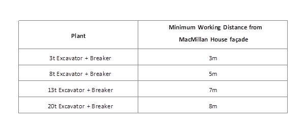
Table 2 – Minimum working Distances Maintaining 3mms-1 PPV
The guide wall trial results indicated that using large excavator mounted breakers (e.g. above 8 tonne) would not be possible given the proximity to MacMillan House required.
Construction Options
A process of optioneering was undertaken to assess the alternatives to excavator mounted breakers, in terms of programme, cost, disturbance and building damage risk was performed to minimise vibration as far as reasonably practical.
3 main options were considered as follows;
• breaking the whole structure (with small • Hydro-demolition (a high pressure water jet which is very noisy and expensive, but which generates lower levels of vibration than traditional percussive methods),
• Drill and burst (a process of drilling holes into the wall and then using a hydraulic splitting device to induce cracking between the holes – this generates low levels of noise and vibration, but is very costly both financially and in terms of time).‘Best Practicable Means’, as defined by Section 72 of the Control of Pollution Act 1974 formed the basis of the decision making process. The costs involved with the latter 2 options could be considered prohibitive for most projects, but given the scale of these works and the potential severity of impacts, mitigation on this scale was considered appropriate.
Chosen Option
The project team developed and refined a method of drill and burst for reducing the diaphragm wall height which was based on proven techniques. The construction method is summarised as follows:
A. Core drilling: vertical and horizontal core holes are drilled into the d-wall on a specified grid to allow the concrete to be broken up into small sections using hydraulic bursting.
B. Hydraulic bursting: hydraulic bursting equipment is placed into the holes and pressured gradually and progressively to induce controlled cracking between the holes, reducing the concrete into small sections.
C. Concrete removal: the concrete is removed from the wall using an excavator machine and loaded into lorries for removal from site.
D. Process A to C is repeated: this process is repeated until the wall height is 1.4m above the ‘cut off level’, or level at which the roof slab is created. This part of the d-wall contains reinforcement steel, which ties into the new roof slab. The roof slab is approximately 1.4m thick.
E. Rock drilling: The upper section of the d-wall is not reinforced, however, the lower 1.4m of the wall immediately above the site of the roof slab construction contains reinforcement to tie in to the roof slab. Diamond core drilling cannot be used since it creates a very high risk of cutting through the reinforcement. A rotary percussive rock drill must be used to create the holes for the final stage of bursting. This method creates moderate noise and vibration. Noise screens were erected around the work area.
F. Process B is repeated: the concrete is broken up into smaller pieces using the bursting method.
G. Concrete removal and final breakdown: Once the concrete is broken into smaller pieces using the bursting technique a breaker must be used to break away the concrete from the reinforcement.
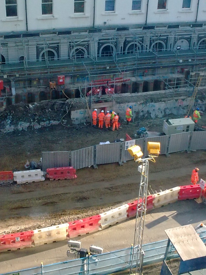
Figure 7 – Concrete bursting method in progress (Stage B).
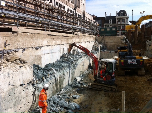
Figure 8 – Removal of burst concrete in progress (Stage C).
Vibration Criteria Upward Adjustment
Even though percussive methods were mainly avoided, it was still considered that there was a significant risk of exceeding the 3 mms-1 limit due to the close proximity of operations such as removing the broken concrete. So, although the risk of exceeding the limit was minimised, it was necessary to secure an uplift in the limit in those area of work which were closest to MacMillan House.
The vibration monitoring results from the earlier trials were written up and used to agree higher limits for different parts of MacMillan House and set out the control measures that would be in place throughout the works.
The Paxton Canopy was considered suitably robust to withstand groundborne vibration levels of up to 10mms-1 PPV without risk of damage.
The MacMillan basement structures were deemed to be resistant to higher vibration levels and a revised limit of 10mms-1 measured on the inside face of the basement walls was agreed.
MacMillan House was also thought to be suitably robust to withstand increased vibration levels of up to 10mms-1, however the condition of the original lath and plaster ceilings was not fully understood because of limited access to large areas of the building and therefore a limit of 3mms-1 (measured at façade plinth level) was retained.
Because the Paxton Canopy and basement structures project beyond the main façade line towards the site (and are in fact the closest section of the building to the worksite), uplifting the limit in these 2 areas allowed far higher levels of vibration to be generated on-site.
It was not practical to have the vibration and heritage specialists in attendance for the duration of the works, so 3 vibration monitors were installed and configured to send alerts to appropriate personnel should the limits be exceeded (negating the need to have a specialist in attendance).
For all work in close proximity to the paxton canopy and the brick retaining wall, vibration was measured on the pavement immediately in front of the canopy and retaining wall. At this position the vibration limit was 10 mms-1. This provided a cautious approach, as coupling losses (reductions) in vibration are known to occur when ‘free-field’ vibration propagates into a large adjacent buried structure.
For work in close proximity to the MacMillan House basements, vibration was measured inside the basements on the wall facing the construction site and on the external plinth of the Macmillan House facade. The vibration limit in the basement was 10 mms-1, but 3mms-1 at the façade plinth. If vibration levels are measured below 10 mms-1 in the basement but exceed 3mms-1 at the façade plinth, works would have been stopped.
Summary of Final Agreed Vibration Trigger Levels in Specific Circumstances
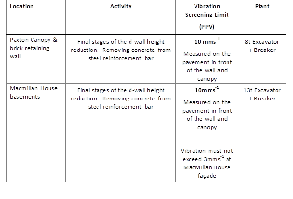
Table 3 – Proposed Vibration Screening Limit in Specific Circumstances
Results as Works Progressed
Real-time vibration monitoring results were also displayed on a screen in the office (by the window). An engineer was responsible for keeping these results under review whilst watching the works through the window and was in contact with the site operatives on a radio throughout to make recommendations or stop works if required.
A benefit of this real-time system was that the engineer observing the works could witness what was causing the high magnitudes and suggest a number of improvements to the working method.
For example, initially the method didn’t include any vertical core holes, so bursting was limited to horizontal core holes in the wall face. This resulted in the creation of large irregular shaped sections of broken concrete. These sections of concrete where then removed from the wall using an excavator machine fitted with a tooth bucket. The large concrete lumps proved difficult to remove leading the machine operator needing to prize and lever at them, resulting in the excavator bucket dragging and banging against the diaphragm wall causing high vibration magnitudes.
Work was halted to allow further core holes to be installed with concrete bursting to reduce the size of large sections of broken concrete. As a result of this period of monitoring and learning the following improvements were made to the working method:
1. The spacing between core holes was reduced.
2. Vertical core holes were also drilled and burst to half the thickness of the concrete lumps.
3. The excavator bucket was replaced with a single curved tooth to pull concrete lumps from the wall. This equipment was found to be significantly more effective and less likely to generate high vibration magnitudes.
Conclusions
The case study outlines a structured and responsible approach to continuous review and adjustment of vibration thresholds at a heritage structure.
Although the initial vibration thresholds may be considered precautionary, it is the process that was followed that is of particular use for future projects.
Physical inspection and assessment of the building in conjunction with site based vibration monitoring trials were used to understand the specific vibration risks associated with the works.
This allowed an upward adjustment in the vibration trigger levels to be agreed, based on the results of the trials, to confirm and validate vibration data with reference and review of the British Standards and the Association of Noise Consultants publication Measurement and Assessment of Groundborne Noise and Vibration.
The masonry building proved to be very resilient to vibration levels, up to the measured peak of 12.5mms-1. It is likely that the building can withstand far higher levels of vibration, however due to the lack of access to investigate the vulnerable plaster ceilings meant that this could not safely be determined and hence any further adjustment uplift was not pursued.
The drill and bursting construction method detailed in this case study was very effective at minimising noise and vibration and can be considered a proven alternative to traditional methods.
Where historic buildings contain vulnerable fabric such as plaster ceilings and decorative surfaces, it is recommended that vibration monitoring be located immediately next to these locations to determine how vibration levels reduce through transmission through the building fabric. Experience at Paddington station indicates masonry structures composed of lime mortar and London stock bricks dissipate vibration levels remarkably effectively.
References
[1] – “Heritage at Risk Report”. Historic England (previously English Heritage). July 2010.
[2] – “Listed Buildings”. Historic England (previously English Heritage). (https://historicengland.org.uk/listing/what-is-designation/listed-buildings/)
[3] – Section 4.2.3. of ANC Guidelines – Measurement & Assessment of Groundborne Noise and Vibration 2nd Edition 2012.
[4] – BS 7385: Part 2: 1993
[5] – ANC Guidelines – Measurement & Assessment of Groundborne Noise and Vibration 2nd Edition 2012.Reference Documents:
C405-SKC-T1-RGN-B071_WS077-50027 + trial reports.
Crossrail Construction Code
Heritage Deed (plus C132 heritage reports)
BS 5228: Part 4: 1992
BS 5228: Part 2: 2009 / 2014
BS 7385: Part 2: 1993
ANC Guidelines – Measurement & Assessment of Groundborne Noise and Vibration 2nd Edition 2012.
DIN 4150-3: 1999 – Structural vibration – Effects of vibration on structures ENV 1993-5, Eurocode 3: Design of steel structures – Part 5 -
Authors

Andrew Bird BSc (Hons) MIOA - Crossrail Ltd
Andrew was appointed as the Acoustic Manager at Crossrail in 2015, with responsibility for providing specialist noise and vibration advice to the Crossrail programme, promoting a consistent approach to noise and vibration issues on construction, fixed plant and the operational railway and identifying and disseminating best practice and lessons learned.
Andrew has 10 years experience in acoustic consultancy and has been with Crossrail since 2011. During these 10 years Andrew has had significant involvement in major infrastructure projects, resolving construction noise and vibration issues, producing environmental impact assessments and consent applications. This includes Crossrail, Thameslink, High Speed 2, Thames Tideway, and Defence Training Academy St Athan.
Andrew has also managed the acoustic design of several significant architectural projects, including school, hospital, residential, office, commercial and religious buildings. During this time he has gained experience of advanced noise and vibration modelling, monitoring and data analysis. Andrew is a committee member of the London branch of the Institute of Acoustics and is a Science Technology Engineering & Maths (STEM) ambassador, volunteering in Schools.

Colin Cobbing BSc(Hons), CEnvH, MCIEH, MIOA - Arup, Crossrail Ltd
Colin has 30 years experience in acoustics. He has spent most of his career working on major infrastructure projects, spanning all different stages of scheme development ranging from: project inception, obtaining major consents, design and specification, procurement, construction, completion and commission testing. The majority of his time has been supporting promoters of schemes and contractors. He has also supported local authorities in the discharge of their planning and environmental health duties.
Colin prides himself on working openly and collaboratively with local authorities, communities and other stakeholders to reduce the scale and extent of noise impacts arising during the construction and operation of major projects.
He joined Crossrail in 2009. Prior to that he was the Noise and Vibration Manager for Network Rail on the Thameslink Programme and for the Hitchin Grade Separation Project. Between 2009 and 2015 he was Crossrail’s Noise and Vibration Manager in the Sustainability and Consents Team. In 2015 he scaled back his involvement to focus on leading the Acoustics Team at Arup. However, he still continues his involvement and is overseeing the completion of the design and installation of the Crossrail track systems in the central section.

David Keeley - Crossrail Ltd
Historic Building Specialist

Suzanne Bryon BSc (Hons) AIEMA - Crossrail Ltd
Suzanne is an Environmental Advisor at Crossrail. She joined the project in 2011 as an EMS co-ordinator and was involved in developing and implementing Crossrail’s Environmental Management System. She then moved into the delivery team in an Environmental advisor role and is currently responsible for working with contractors to ensure that construction work is undertaken in compliance with the Environmental Minimum Requirements, and for promoting world class performance and driving best practice. The environmental advisor role includes responsibilities such as being instrumental in the process for obtaining and complying with consents, facilitating collaboration between contractor, technical and delivery within CRL and then between client contractor and statutory bodies as well as working with stations contracts to achieve BREEAM certification. Prior to Crossrail, Suzanne had 5 years experience working for a civil engineering contractor on highways and airports projects.

Kenneth Hills - Costain Skanska Joint Venture
Kenneth has 10 years’ experience of acting as the Client, Principal Contractor and Enforcement Body working on complex infrastructure improvement schemes in the urban and rural settings. He has successfully developed and implemented Environmental/Sustainability strategies over regional and national area’s on award winning multi-billion pound tunnelling, railway, major civils and multdisplinary projects such as: HS2, Crossrail, East London Lime/North London Railway Improvement Programme (London Overground), Intercity Express Programme, Kings Cross Station Upgrade, 2012 Olympic, Stratford Station Upgrade. In addition acting as the Environmental Lead for Network Rail Maintenance Division ie. Routes: North East, East Anglia (incl:Essex) and Kent. Very strong understanding and knowledge of Environmental Legislation, Initiatives, ISO 14001 certification, PAS2080, ISO20400, responsible procurement and current sustainability issue’s. Other strong areas are Project Management, Stakeholder Relations and building high performing project teams.

Rick Methold - Southdowns Environmental
Rick is a Director at Southdowns Environmental and has over 25 years’ experience in dealing with noise and vibration on major infrastructure projects in the UK and overseas. Rick began his career working on projects such as High Speed 1, and has been advising various main contractors across the Crossrail project since 2009 including those associated with station construction, tunnelling and track systems. Rick sits on the Working Group for British Standard 5228 and is the lead Noise and Vibration Specialist for CSJV at Paddington Station.