Amalgamation of Tunnel Secondary Lining and First Stage Concrete at Whitechapel Crossover
Document
type: Technical Paper
Author:
Michal Uhrin MSc CEng, Richard Brierley, Mike Talliss, Eric Marchand, ICE Publishing
Publication
Date: 30/09/2017
-
Read the full document
1 Introduction
1.1 Background and original design
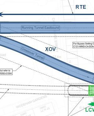
The Whitechapel Crossover will provide two switches for the transfer of railway traffic between the eastbound and westbound Crossrail tracks. In tunnelling terms, the works making up the Crossover form a westward extension of the sprayed concrete lined (SCL) tunnels of Whitechapel Station. The location within Crossrail is shown in Figure 1 below:

Figure 1 – Location of Whitechapel Crossover
The SCL tunnels include (Figure 2):
- Two tapering caverns of over 17m excavated diameter (EBX, EBC and WBC) with completed width of almost 15m and completed internal height of the structure is circa 12.5m;
- a crossover tunnel connecting the two caverns (XOV);
- tunnel boring machine (TBM) launch chambers for the eastbound and westbound drives towards Liverpool St and Farringdon (LCE and LCW);
- a section of running tunnel on the eastbound track (RTE);
- an extension to the westbound platform tunnel (EPTW); and
- a temporary bypass tunnel, which allowed the SCL contractor, C510, to undertake works on the eastbound tunnels prior to gaining access through the adjacent Durward Street Shaft.
The tunnels are identified on the drawing excerpt below:
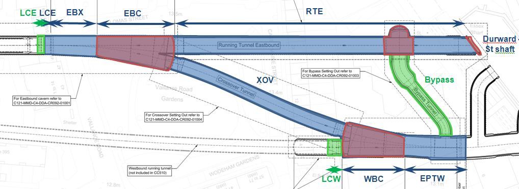
Figure 2 – Whitechapel Crossover tunnels
The tunnels were traditionally excavated and a primary SCL layer was applied. This paper considers the subsequent construction of the secondary linings of the tunnels in the Whitechapel Crossover.
The original design of the tunnels foresaw the application of a continuous sprayed and/or sheet waterproofing membrane together with a thin non-steel fibre regulating/protection layer over the inside face of the primary lining, then the application of a secondary lining consisting of a cast in situ reinforced concrete (RC) invert slab, cast in situ RC side walls and an SCL arch, in most cases reinforced with steel fibres only, but in some cases (e.g. junctions, headwalls) including steel bar reinforcement. At this stage, the tunnel structure would have been complete and the tunnels ready for the internal track bed build-up and fit- out.
The track bed design originally consisted of first stage concrete (FSC), typically 1 m thick mass concrete, and second stage concrete (SSC), varying from around 100 mm to 500 mm depending on the cross-section. The sleepers are to be partially embedded into the SCC. To protect the track bed, a pressure relief drainage system (PRD) was proposed between the secondary lining of the tunnel and the FSC. This would have allowed any water trapped at this interface in the operational phase to vent out to the tunnel interior under the load of a train passing, rather than causing potentially damaging impact loads to be applied to the FSC. This arrangement is presented in Figure 3 below:
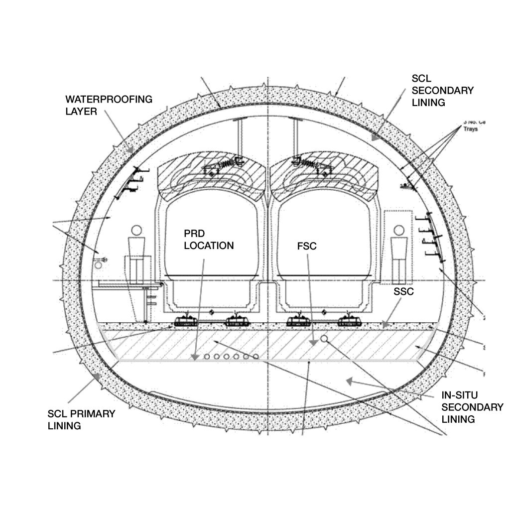
Figure 3 – Typical cross-section with the original design
1.2 Revised design proposal
The design of the secondary lining was modified to include the FSC and the cast in situ invert slab of the secondary lining into one single structure. This meant that the two structures became one concrete pour, allowing a faster overall construction programme. The programme saving was estimated at two months for the entire Crossover. The resulting cost saving on the C510 contract was estimated at £1,000,000.
Further implications for the cross-section of the tunnels were:
- the incorporation of various services into the secondary lining invert;
- re-design of the PRD to allow for a new location between the FSC and SCC, due to the previous location no longer being a construction joint;
- the opportunity to optimize protection concrete on the sheet waterproofing membrane at base (bigger thickness and extent giving more efficient construction platform);
- the opportunity to leave in some of the (previously temporary) TBM transit concrete, which contributed considerably to the time savings; and
- reduction in the quantity of reinforcement in the vault lining.
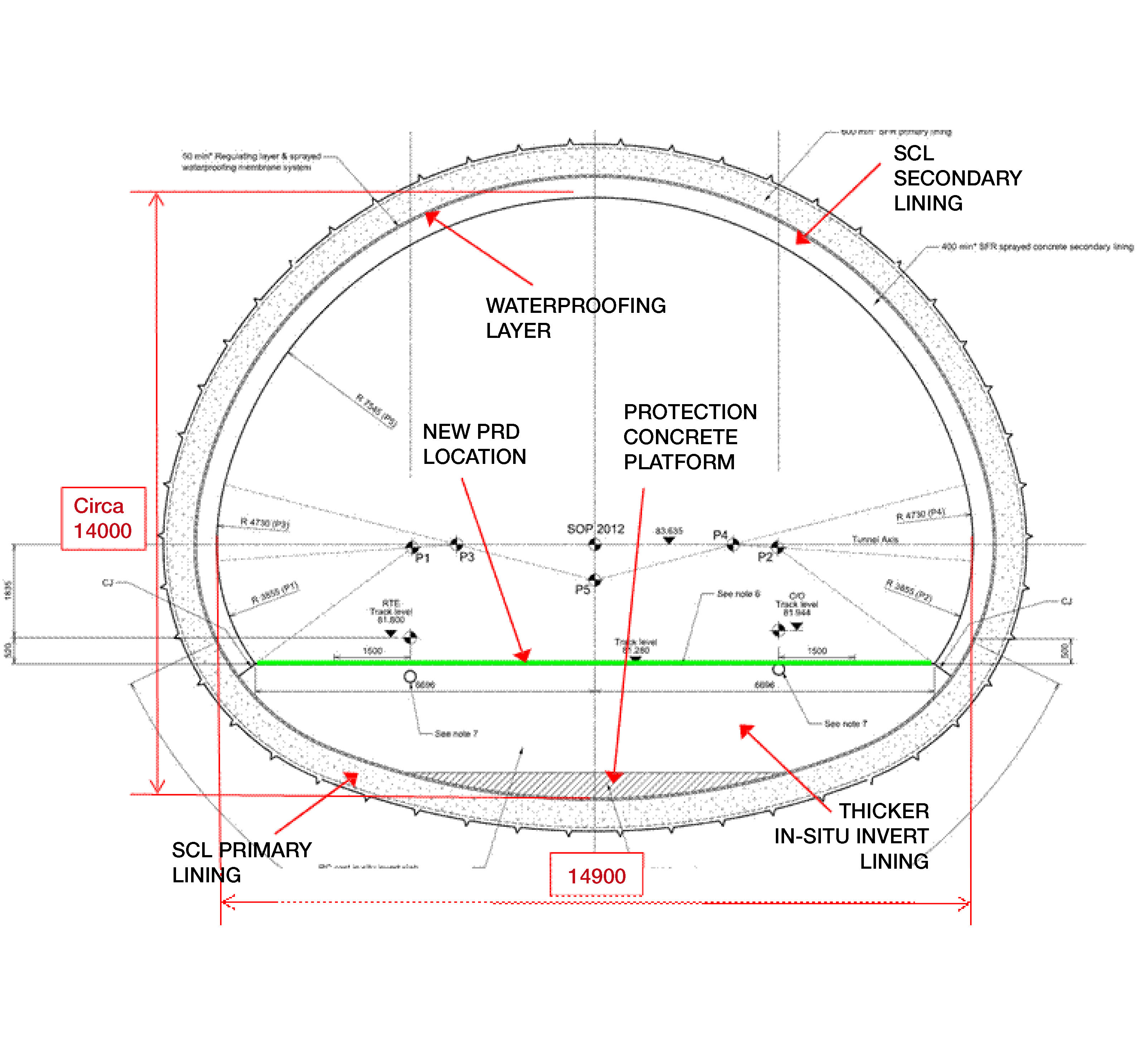
The typical cross-section for this arrangement is shown in Figure 4 below and a schematic comparison to the original design in Figure 5:
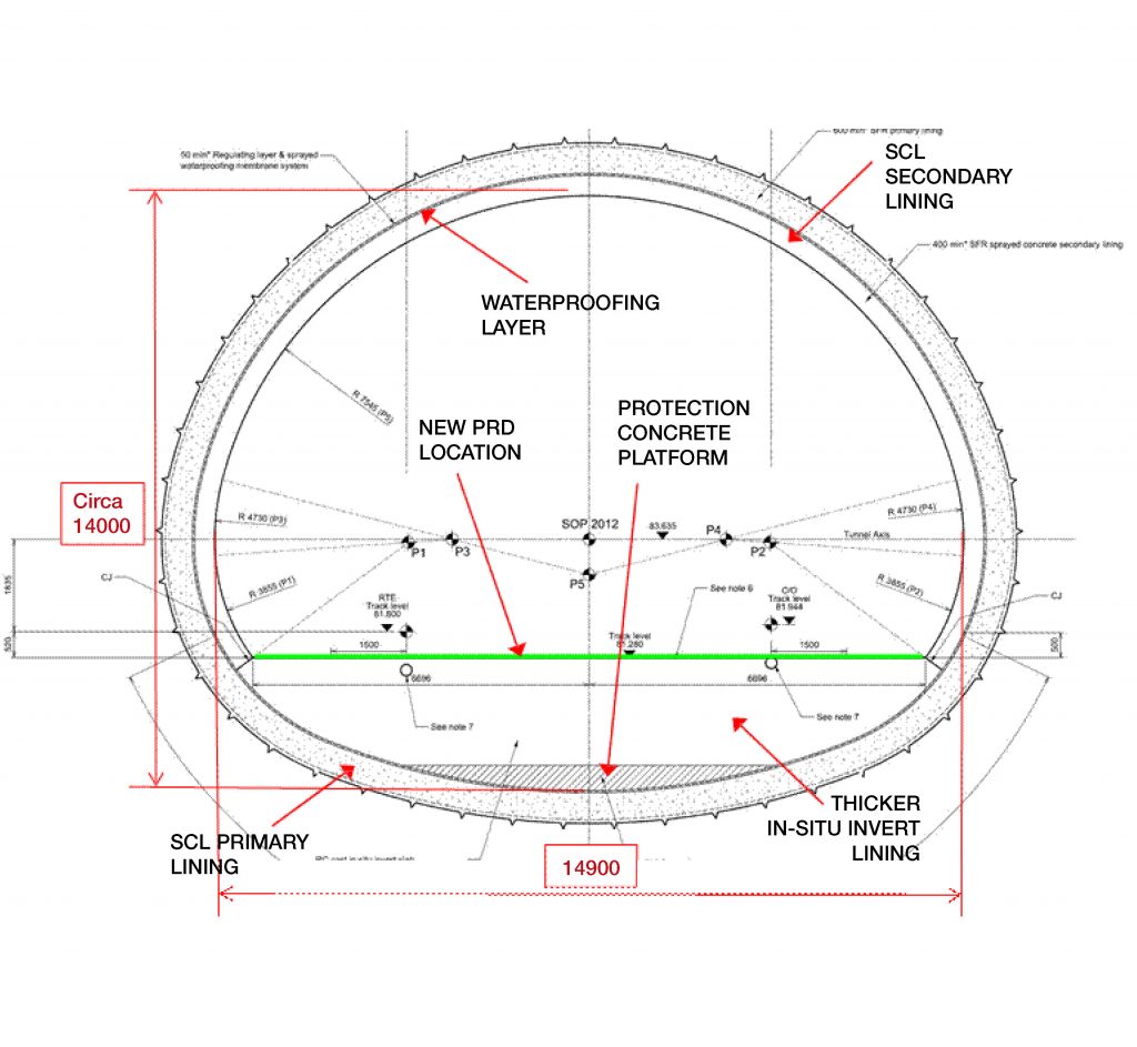
Figure 4 – Typical cross-section with the new design
The following sections consider the implications of the changes described above for design and construction and conclude with recommendations for any future railway and metro works that use or consider such an approach.
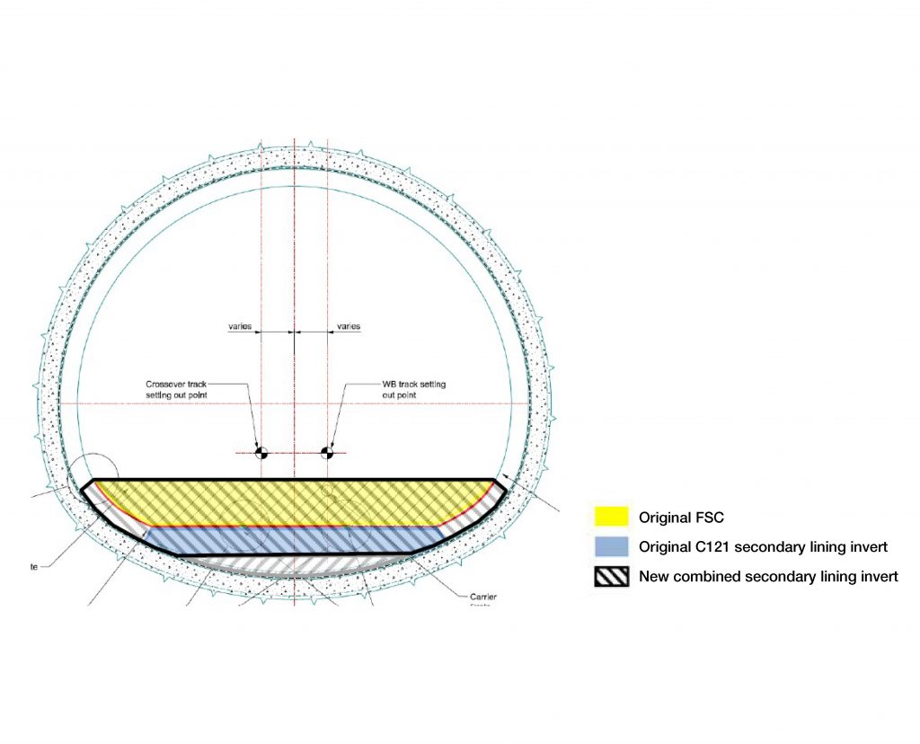
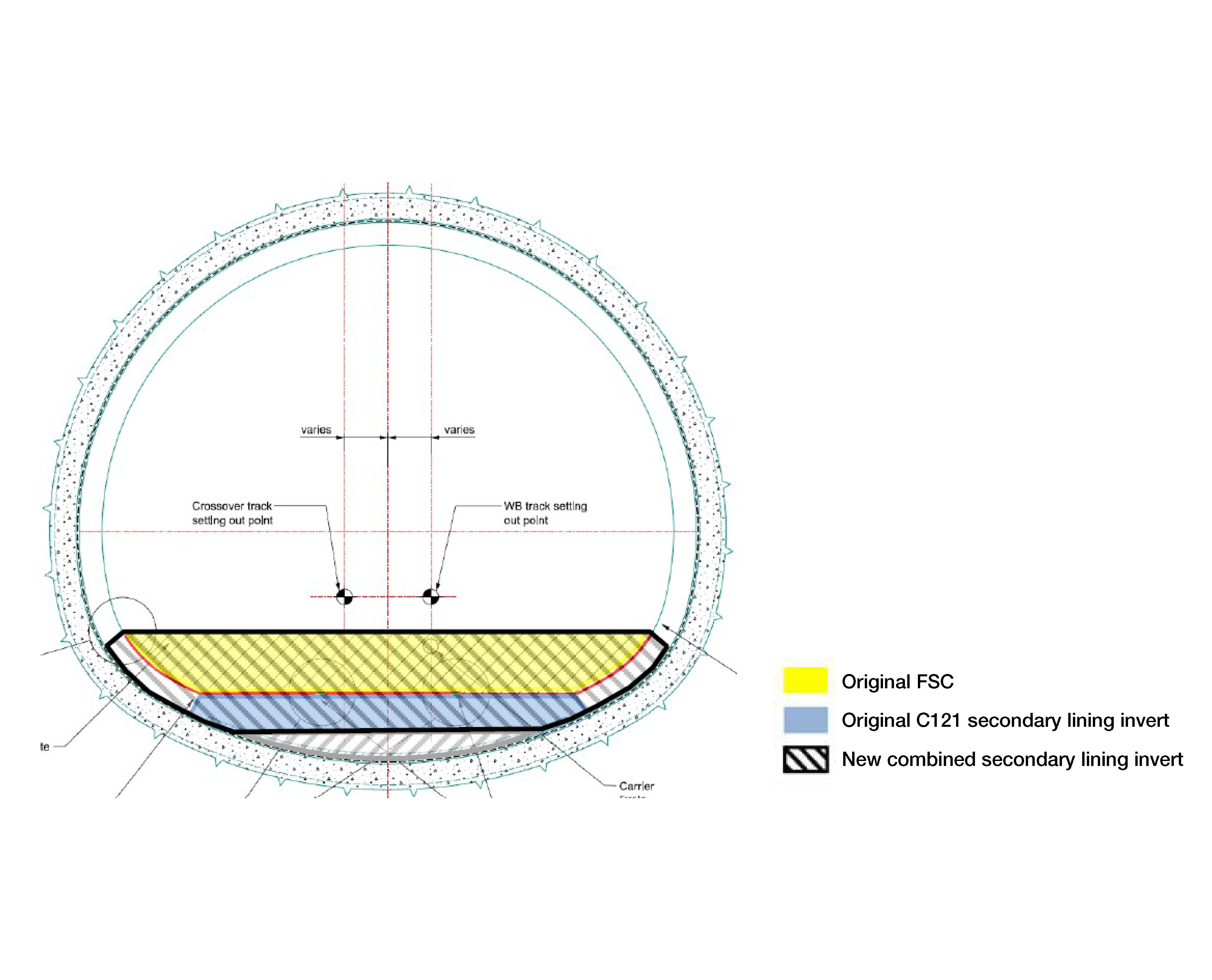
Figure 5 – Schematic comparison of the original and the new design
2 Design of combined FSC and secondary lining
2.1 Design methods
The secondary lining/FSC combined structures were typically designed to take the following loads:
- self-weight;
- groundwater pressure;
- the proportion of the effective stress (ground load) not carried by the primary lining in long-term conditions, usually determined by numerical modelling;
- summer and winter temperature gradients;
- concrete shrinkage strain; and
- internal loads due to passing trains.
Tunnels (remote from junctions) are modelled in 2D (plane strain) with the actual geometry and loads applied. The reaction forces from the ground are modelled as an array of spring beams corresponding to the ground stiffness. Junctions, headwalls and other situations with significant 3D-effects are modelled in 3D according to similar principles. The output of the models is used to design the structures as steel rebar or fibre reinforced concrete according to Eurocode 2 and RILEM guidelines for fibre reinforced concrete. The method is not described in detail in this paper, rather the differences due to the amalgamation with the FSC are discussed. Other than the introduction of the internal track loads, the differences in method relate to non-structural issues.
2.2 Track loads
In the original design the track loads were dispersed significantly via the FSC before reaching the secondary lining whereas in the new design they were applied in more concentrated form. However, this change had only a minor impact on the tunnel lining design as such due to the robust nature of the lining – invert slab especially – designed for high external loads.
Nevertheless, it was necessary to protect ducts cast in the concrete from being crushed by the concentrated track loads. The most critical elements in this respect became the track drainage pipes within the crossover caverns due to higher SSC thickness required below track switches and due to differences of vertical alignment between the main line track drains and the crossover tunnel drain. Reinforcement was detailed above and around the pipes for protection. Stainless steel bars were specified above the pipes where only sub- standard cover was available.
Track loads had also impact on considerations for the new pressure relief drainage design, explained further below.
2.3 Services and track drainage
The original Employer’s design for the services crossings through the FSC for non-station areas of Crossrail was largely a performance specification. There was a requirement for an under-track crossing (UTX) consisting of a plastic duct for general use every 30m along the running tunnels. More specific requirements were given for a fire main crossing underneath the crossover track near the headwall of both the eastbound and westbound caverns. Further details were to be worked on by the system-wide contractors, in this case C610. Track drainage was fully detailed, including pipe diameters, the location of catchpits and inlet and outlet pipe levels by C122.
To correctly install all the cast-in services, the tunnel contractor C510 required drawings showing the setting out and details of all such services. Coordination was therefore undertaken between the SCL designer C121 and the system-wide contractor C610 to ensure all necessary services were catered for. The services were recorded on C121 drawings. The viability of the amalgamation therefore depended on a sufficient level of design of the services being available to allow details to be set.
Particular attention was paid to the RC detailing in C121 drawings where services penetrated the top surface of the FSC. This was necessary to avoid clashes with reinforcement as far as possible. The drawings referred to established specifications for high-voltage and low voltage cable ducts, drainage pipes and draw chords as necessary.
The fire main crossing (Figure 6, shown in red colour) posed a particular challenge in that it formed part of a continuous system to be designed and constructed by another contractor (C610). The solution was for C610 to provide the geometry and specifications, recorded on C121 drawings, and for C510 to procure the short length necessary for the crossing, complete with flanges to enable connection to the remainder of the system by C610 at a later date. Given that the section embedded in the FSC will not be accessible for maintenance, this part of the pipe was required to be stainless steel and continuous rather than having straight and curved sections connected with flanges.
The issue of lack of maintenance access mentioned above was a key issue to be resolved to demonstrate viability of the amalgamation of FSC and secondary lining. If the FSC were separate, it would be possible to remove sections of it at a later date for maintenance of the FSC itself, the track, or services, or installation of any new equipment/technology that may emerge within the 120 year design life of the tunnel structure. This ability is removed if the FSC forms an integral part of the tunnel structure. The buy-in of the infrastructure maintainer, Railway for London, was therefore sought and acquired at an early stage.
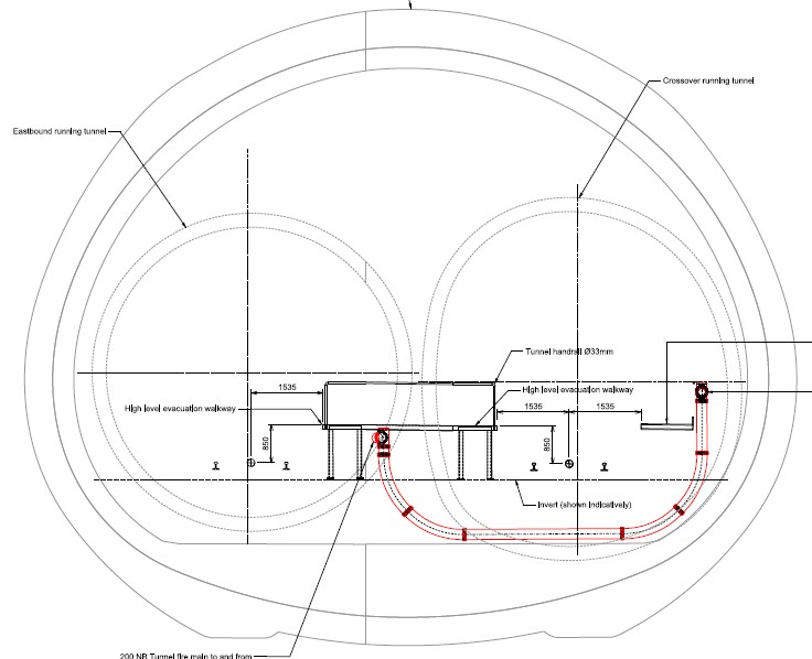
Figure 6 – Fire main crossing schematic
2.4 Pressure relief drainage
The purpose of the PRD system is to protect the track bed from pumping action by trapped seepage water. In a number of projects, most notably the Heathrow Express tunnels, damage has been caused to the track apron due to hydraulic action. It has been observed that water ingress through leaking joints in the segmental lining has penetrated into the construction joint between the tunnel segmental lining and the FSC. Transient train loading has pressurised this water and caused it to hydro-fracture along this construction joint. With time, separation of the track bed from the segmental lining has occurred over an extended area. In these areas significant cracks have developed through the track apron creating a water path to relieve these transient pressures. To avoid this problem it has become modern practice to incorporate pressure relief drains beneath the FSC. These drains provide a low resistance flow path for any water that seeps through the lining leading into the track drainage system.
On the Crossrail projects PRD details have been developed by C122 for all tunnel configurations including SCL. In the original design the PRD was naturally located on top of the secondary lining below the FSC in orthogonal grid following joint locations in the secondary lining with typical drain details as shown in Figure 7.
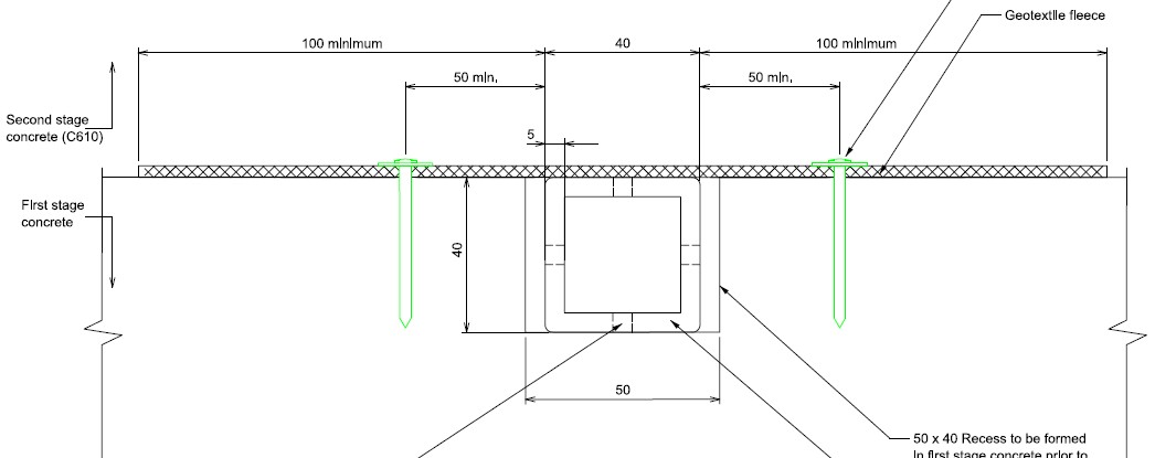
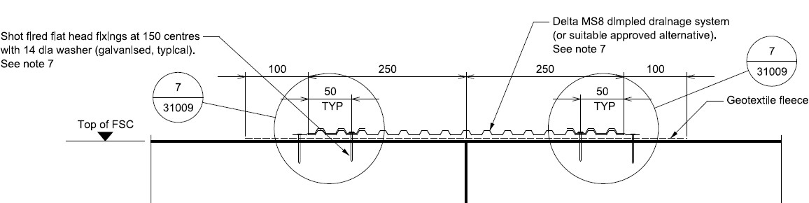
In the new design the original interface for PRD installation no longer existed and to maintain its purpose of track protection it had to be moved below the SSC. However, the original drain details could not have been repeated because of risk of being crushed by track loads from passing trains. Alternative details were investigated eventually leading to reference design based on penetrated stainless steel drains installed in recesses into the FSC top surface (Figure 8).
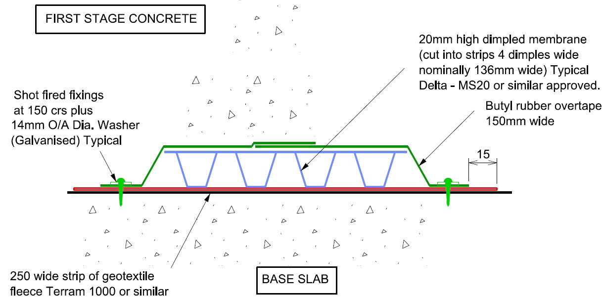
During development of the detailed design further optimization was sought based on cost of stainless steel and foreseen difficulty to build the recesses in the top of the FSC including all connection details and interface details (e.g. at steps in FSC level and at ends of the extent of FSC amalgamation). Final design (Figure 9) was achieved by modification of the original design using a thinner Delta Drain and allowing the ‘egg cups’ to be filled by the SSC concrete and thus provide resistance against crushing from track loads. The system could be installed on clean flat FSC surface before construction of the SSC.
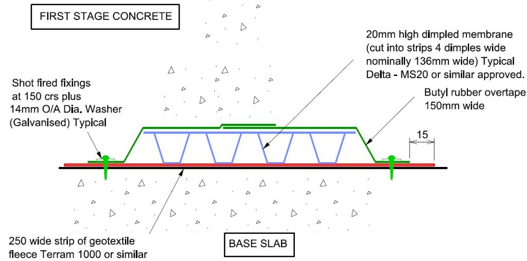
Figure 7 – Pressure relief drain below FSC

Figure 8 – Pressure relief drain below SSC
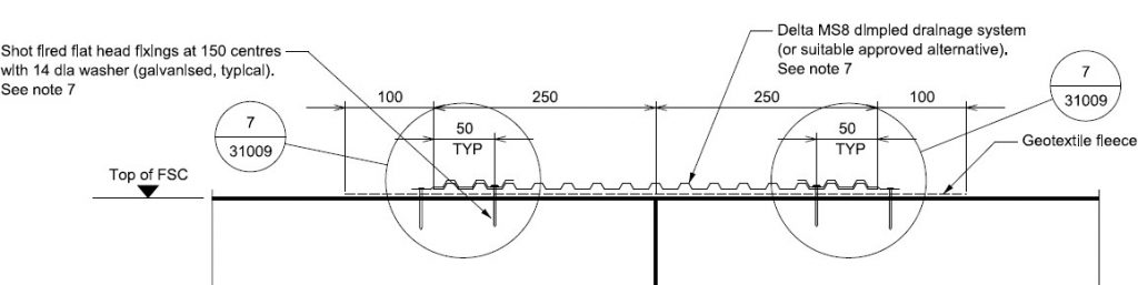
Figure 9 – Pressure relief drain below SSC, final design
2.5 TBM transit concrete
The TBMs were pulled through the Crossover from east to west and used to drive the running tunnels westwards from SCL launch chambers attached to the westbound and eastbound caverns. At the time of TBM transit, only the primary lining was constructed in the Caverns and running tunnels outside the limits of the platform tunnel. A temporary layer of concrete between 500mm and 1000mm thick was placed in the invert of the tunnels to mount the TBM transit rails. The concrete consisted of a flat invert section and two upstands, onto which the rails were fixed.
As the transit concrete would have stood higher than the secondary lining invert and therefore clashed with the FSC, the original concept was for the entirety of the temporary TBM transit structure to be removed before application of the waterproofing membrane and construction of the secondary lining by C510. Installation of the first stage and secondary stage trackform would then follow by other follow-on contractors.
A review of the overall construction for the station tunnels, station fit out and track infrastructure affecting Whitechapel Station, established that an overall saving could be achieved by taking the opportunity of combining works to construct secondary lining and first stage trackform within the C510 activities, thereby relieving certain activity by the track infrastructure contractor in the Westbound and Eastbound caverns, Crossover Tunnel and East Bound Running Tunnel (EBRT).
In the caverns it was necessary to remove the temporary TBM structure to construct a combined secondary lining and FSC. However, in the eastbound running tunnel, there arose the opportunity to retain part of the transit concrete in place, placing the waterproofing membrane on top of the transit concrete and casting the secondary lining/FSC combined structure on top of this. In the caverns, this was not found to be practical as the remaining secondary lining invert was too thin to carry the imposed loads, as shown in Figure 10 below over the much wider and flatter profile of the caverns:
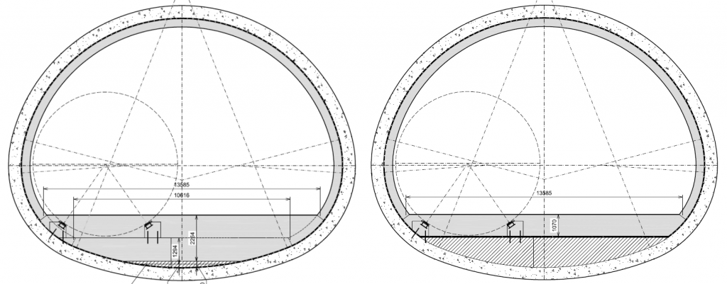
Figure 10 – Cross-section of cavern with TBM concrete taken out (left) and left in (right)
In the Running Tunnel Eastbound (RTE) however, it was found that the flat part of the transit concrete could be left in place. This presented savings in terms of cost, time and overall volume of concrete used in the longest tunnel on the Crossover. The comparison of cross- sections for RTE is shown in Figure 11 below:

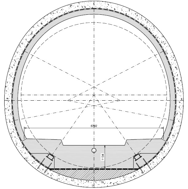
Figure 11 – Cross-section of RTE with TBM concrete taken out (left) and left in (right)
The resulting thinner secondary lining invert required an increase of reinforcement of typically one rebar diameter in the top face. However, the benefit of leaving in the TBM transit concrete outweighed the disadvantage of the additional steel.
2.6 Results and reinforcement
The results showed a typically reinforced invert slab, with top steel ranging from 32 mm diameter bars at 100 mm spacing in the biggest sections down to 20 mm bars at 200 mm spacing in the smallest sections. In most cases, shear reinforcement was needed in the invert at the joint to the arch. The typical reinforcement therefore resembled that of a bridge deck, as shown below (Figure 12) with details around cast-in services:
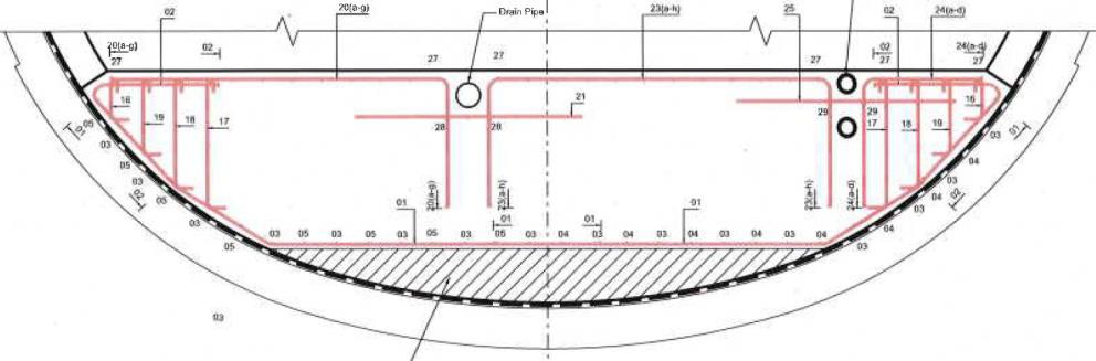
Figure 12 – Typical RC details
It was found that the additional thickness, and therefore stiffness, of the invert drew bending moments away from the arch and into the invert. This had the result of reducing the reinforcement needed in the arch. In all cases except junctions and headwalls, where longitudinal effects are significant, the arch could be designed using steel fibre reinforcement rather than rebar. This provides greater safety by design by removing the number of working at height operations.
3 Construction of combined FSC and secondary lining
3.1 Speed of construction
The changes to construct the combined FSC and secondary lining increased the scope of works to be undertaken by C510, but reduced the activities to be undertaken by follow on Contractors. The benefit to the project as a whole came from the ability of C510 to realise the opportunity to bring forward works into the C510 Station Tunnels contract which would otherwise be undertaken by follow-on contracts at a time when schedules had become misaligned by various circumstances.
In the Caverns and Crossover Tunnel, the sequence of works was to:
- Remove the TBM transit concrete to expose the primary lining. The depth of temporary concrete reached 2.1m.
- Prepare the tunnel surface and install sheet waterproofing membrane and waterbars at construction joints, lay a protection concrete layer over the full length of the cavern, approximately 35m (W/B) and 50m (E/B).
- Erect reinforcement cages and services supported by a scaffold chair system (galvanised scaffold with tubes grouted).
- Cast the bays in volumes of circa 100m3. Height of each pour being about 2m at tunnel centreline.
The maximum bay length was approximately 10m, reducing to approximately 5m as the cavern width increased.
In East Bound Running Tunnel, where a standard tunnel diameter was maintained, the final design allowed retention of the invert of the TBM transit structure (having removed transit haunches and rails), followed by installation of sheet waterproofing and FSC. Thereby avoiding the requirement to remove and recast an equivalent volume of permanent secondary lining with the FSC. The length of each bay was 13m.
3.2 Removal of the temporary construction
Successful trials were undertaken using Nonex (low explosive blasting). This technique was considered successful for local breaking requirements where access could be readily restricted and controlled. However the Cavern and Crossover tunnels were also main thoroughfares within the tunnels and the health and safety restrictions were considered too intrusive upon the work force and other concurrent activities.
Breaking of the concrete was undertaken by track sawing the surface of the concrete and drilling the surface in a cruciform arrangement at 500mm centres, depth being 500 to 1000 mm. A tracked breaker (weight) was then used to fracture the concrete for removal. This is illustrated in Figure 13.
The method proved successful and inspections did not detect damage to the primary lining.
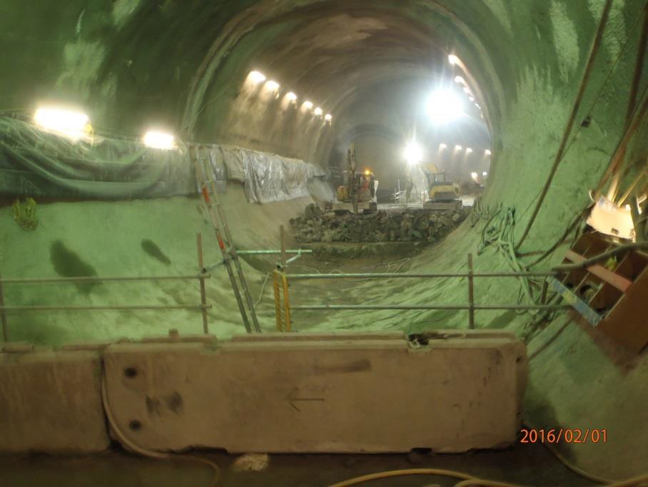
Figure 13 – Removal of temporary TBM transit concrete
3.3 Installation of Sheet membrane
Sheet membrane was laid over a non-steel fibre regulating layer and geotextile membrane to prevent puncturing by protruding steel fibres from the primary lining. A concrete protection layer was cast over the water proofing to provide a platform to construct the FSC bay. A standard level of the connection detail between sheet and sprayed membranes ensured consistent access for installation. Photographs of these activities are shown in Figure 14 and Figure 15.
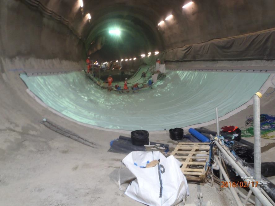
Figure 14 – Placing of sheet waterproofing membrane
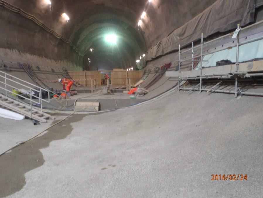
Figure 15 – Protection concrete over sheet membrane and platform for construction
3.4 Casting large volumes and depths of concrete
In the cavern areas where the FSC was deeper, C510 installed a scaffold support frame in each bay on to which the top face reinforcement and services was fixed. The support frame was sacrificial within the pour so comprised galvanised steel tubing which cast itself grouted before casting the FSC. The nature of the support is indicated in Figure 16 and shown in Figure 17.
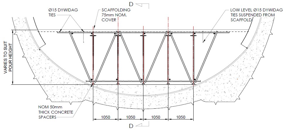
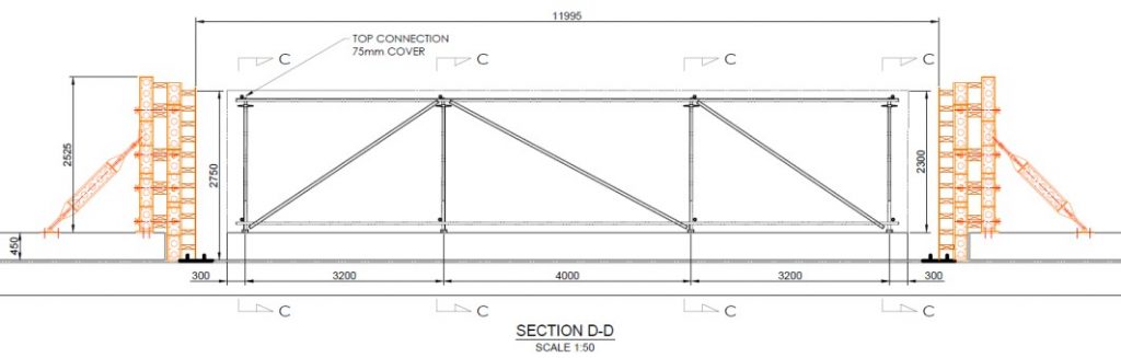
Figure 16 – Scaffold support structure
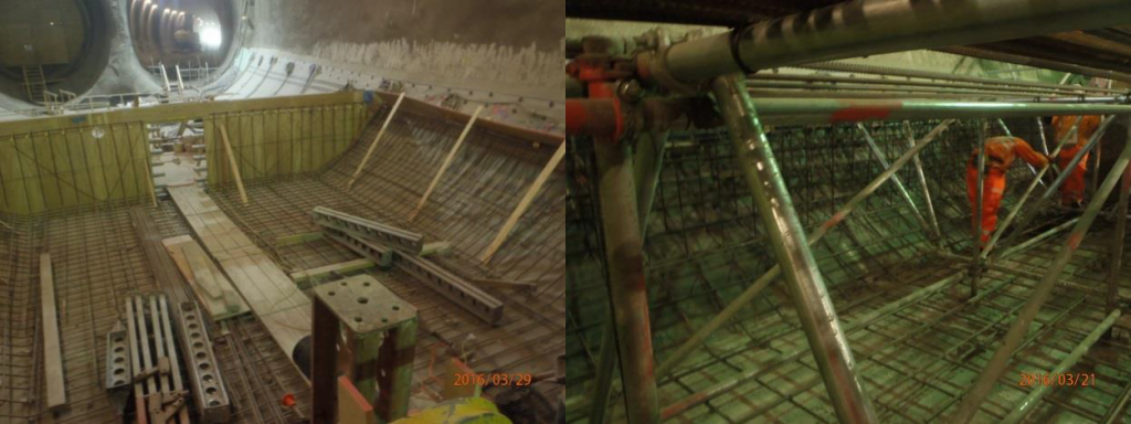
Figure 17 – FSC bays under construction
Concrete supply to the works was from the on-site batcher normally used to provide material for the sprayed concrete linings and smaller cast linings in the tunnels. The capacity was 20m3/hr.
Mix designs were tested and developed on site to take account of requirements to:
- Deliver concrete from the surface into the works, pumping where possible. Target pumping distance circa 150m from shaft bottom.
- Maintain temperatures within the mix (heat of hydration) to a target of 70°C with a maximum thermal gradient from the body of the mix of <25°C. This was achieved by installing a chilled water system at the batcher and incorporating Phoenix low-heat cement.
- Incorporate fire proofing in the form of polypropylene fibre with a dose of 2 kg/m3.
Concrete from the batcher was pumped directly to a transfer pump/re-mixer at the shaft bottom and then delivered by pipeline to the work face. The site experience was that ability to pump the full distance was occasionally subject to interruption by pipeline blockages. This was overcome partially by slight adjustment to the flow of the base mix, and completely resolved by the transfer to 3 m3 mobile re-mixers and hand dosing of the polypropylene fibre directly into the remixer.
High temperatures in the concrete pour during the period of curing is associated with Delayed Entrigite Formation and associated induced concrete damage with Early Age Thermal Cracking. Thermocouples measured maximum temperature and thermal gradients through the mix. Typical maximum temperatures recorded were 72°C with a temperature gradient of 21°C. The measures taken to incorporate low heat cement and batch with chilled water (particularly through the summer period) appear to have been effective. No surface cracking has been observed.
3.5 Incorporation of services
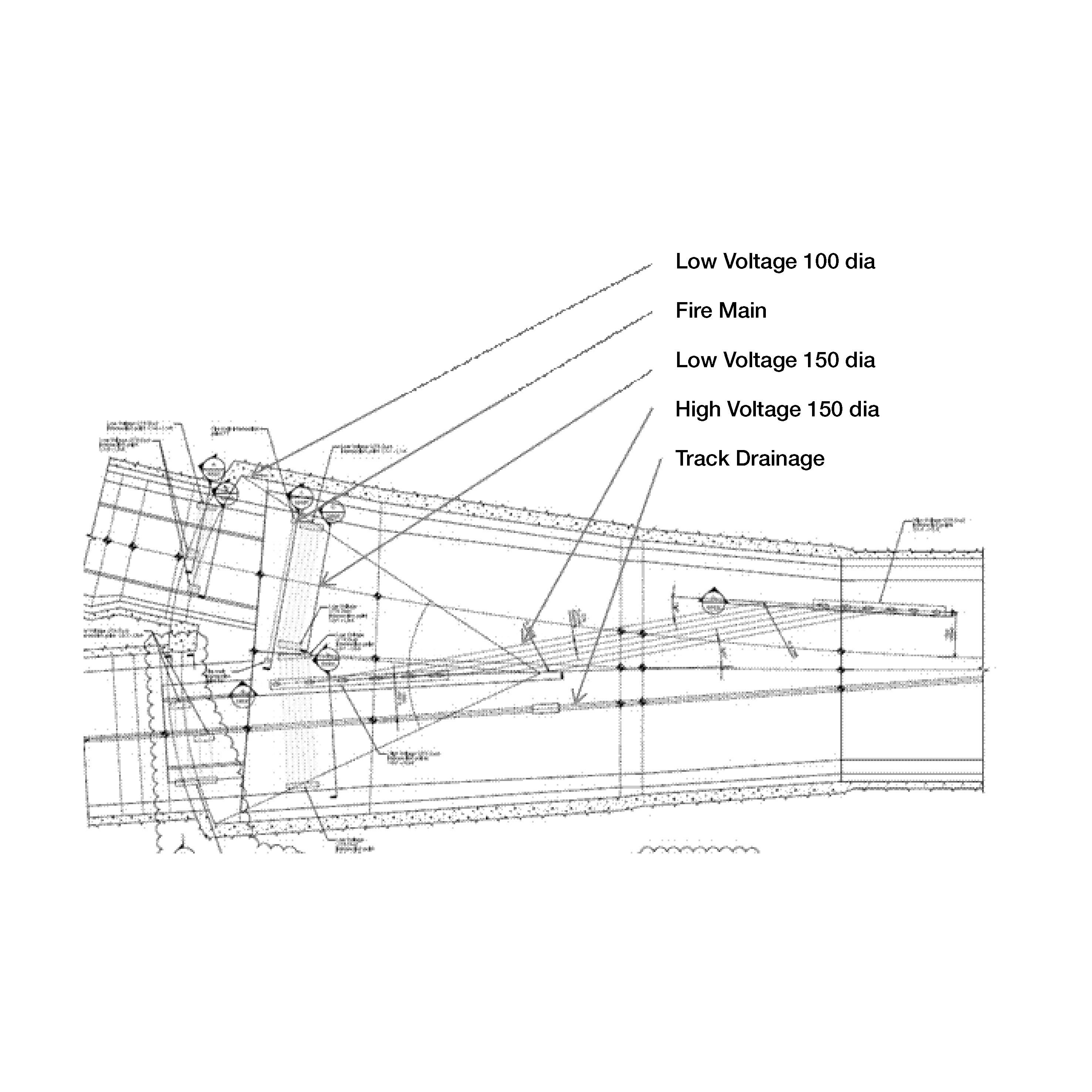
Indicative routes of services in Under Track Crossings (UTX) to be incorporated in the FSC of the Westbound Cavern are shown in Figure 18 comprising: Fire Main, Low Voltage UTX (100 dia and 150 dia), High Voltage UTX (150 dia ) and track drainage (300 dia).
Installation of the services was not straight forward through the various construction blocks between 5m and 10m in length, ensuring that they did not conflict with reinforcement. Particular requirements to maintain continuity of line and falls of the HV Ducts and Track Drainage was required, together with the position of duct outlets adjacent to the future track alignment. The services in Eastbound Cavern were similar.
Coordination of construction details from various Contract requirements was necessary to bring forward works originally to be installed by others into the FSC to be constructed by C510.

Figure 18 – Service Routes – Westbound Cavern
3.6 Adherence to tolerances
Construction tolerances for casting the FSC and installing services which are tighter than norms for secondary lining construction were accommodated satisfactorily by C510.
4 Conclusions
The amalgamation of FSC into the secondary lining invert in the Whitechapel Crossover achieved considerable time and cost savings to works that were on the critical path of the Crossrail central section. The authors consider that the amalgamation can therefore be considered a successful innovation. In addition to cost and time savings, the following benefits were observed:
- The resulting thickening of the invert tends to draw bending moments away from the arch of the tunnel and into the invert, whereby reducing/removing the need for bar reinforcement in the arch, where rebar is more difficult and hazardous to install. A safety benefit was therefore realised. In some cases a thinner arch may be possible for future projects.
For future projects, the following considerations and recommendations are made:
- The FSC typically contains services parallel to or across the track. The detailed design for these services usually lags the tunnel civils design. In the case of combined FSC, enough design of the services must be done in advance to ensure the number, locations, geometry and specification of any cast-in services can be set to meet the design, procurement and construction of the tunnel civils. Alternatively, this interface could be avoided by routing services above the railway kinematic envelope. In the case of drainage however, this will clearly not be possible. The impact of service crossings is likely to be greater if similar proposals are used in stations rather than crossovers or running tunnels.
- The buy-in of the asset owner/maintainer is essential, as the FSC becomes integral to the tunnel structure. Therefore, it cannot be partially or wholly removed during maintenance without special measures to ensure the safety of the tunnel. Any services within the FSC must be designed for an absolute minimum of maintenance/replacement requirements.
- Geometric tolerances for the combined FSC will likely need to be greater than for separate FSC. In particular, it would be extremely challenging to construct the top surface of the FSC with cant or twist, especially if rebar is present in the top face. It is recommended that cant and twist are taken up wholly in the SCC in such cases.
- In cases where TBMs are to be pulled through stations, there may be a benefit in constructing the combined FSC and using this as the transit base. This would remove the need for any further temporary concrete, presenting cost, programme and sustainability advantages.
-
Authors