Back Analysis of Observed Measurements for Optimised SCL Tunnel Design
Document
type: Technical Paper
Author:
Angelos Gakis Dr. Dipl-Ing, MSc DIC, CEng MICE, Ali Nasekhian, Dr-Ing, Stephen Flynn MSc, CEng MIEI, ICE Publishing
Publication
Date: 03/11/2014
-
Abstract
The Crossrail Farringdon Station is a deep level station with two platform tunnels, 300 metres long at a depth of approximately 30 metres below street level. The running tunnels are primarily TBM bored with the platform tunnels enlarged using sprayed concrete lining (SCL) tunnelling method. The station is located in challenging ground conditions due to the presence of several faults and the heterogeneity of the Lambeth Group, which call for a variety of temporary works contingency measures and in-tunnel depressurisation scheme.
Back analyses for the already constructed cross passage CP1 were performed using finite element (FE) analysis in order to calibrate them against observed deformations, deriving valuable information for future tunnel design. In order to achieve this, the accuracy of assumptions made in the initial design stages had to be checked. Such parameters as ground relaxation factor for construction advance, at rest earth pressure coefficient and soil stiffness are back-calculated and compared with the initial values.The outcome of this work was refined FE modelling parameters based on measured deformation results, demonstrating a greater accuracy for predicting both in-tunnel and surface deformations and thus allowing for a better understanding of the tunnel lining and ground behaviour to be anticipated in advance of construction.
-
Read the full document
Crossrail Farringdon Station
The Farringdon Station is one of the 8 Crossrail stations in London that provides an interchange between the Crossrail and existing London Underground networks at the Eastern Ticket Hall/ Barbican Station and an interchange between Crossrail and Thameslink at the western ticket hall/ Farringdon side. The Crossrail Farringdon Station is a deep level station with two platform tunnels stretching between the existing London Underground Farringdon and Barbican Stations at a depth of approximately 30 metres below street level.
The contractor, Bam Ferrovial Kier Joint Venture (BFK), formed between BAM Nuttall Ltd, Ferrovial Agroman (UK) Ltd and Kier Construction Ltd, was awarded the construction contract (C435) for the main construction works at Farringdon station by Crossrail Limited (CRL) in November 2011. The Dr. Sauer & Partners Company Limited (DSP) has subsequently been appointed by BFK to provide sprayed concrete lining (SCL) design and site supervision.
The structures at Farringdon Station are:
- Escalator inclines ES1 and ES2,
- Eastbound Platform Tunnel PTE and Westbound Platform Tunnel PTW (SCL Tunnels enlarged from TBM pilot tunnels),
- Lower concourse tunnels CH1 and CH2,
- Cross passages CP1, CP2a, CP2b, CP3a, CP3b, CP4, CP6a, CP6b, CP7, CP8 and CP9,
- Ventilation adits VA1 and VA2,
- Platform Extension tunnels PL1, PL2, PL3 and PL4,
- Stub tunnels STE1, STW1, and STW2,
- Lift shaft passage (LP1) connection to Thameslink lift shaft and
- Temporary tunnels – PL2RC Wraparound, CP1-CH1 Connection.
At the time that this article was written (October 2013), the completed tunnels in Farringdon station were the ‘’Early Western Tunnels’’, STW2-PL1, CP1 and TBM reception soft-eyes in shafts SH-W1 and SH-W2, as well as CP1-CH1 connection adit, PL2RC Wraparound, CH1 pilot tunnel and westbound TBM pilot tunnel (shown in light blue colour in figure 1). This reports focuses on CP1, a cross passage of approximately 35m length and cross sectional area of approximately 22m2 (7.2m height x 6.2m width).
Figure 1 – Farringdon Station plan view
Design considerations
The analysis and design of buried structures is one of the most complicated and difficult subjects in tunnel engineering. Construction of urban tunnels requires precise measurements of soil settlement at the surface and in-tunnel deformations. Factors such as nonlinear behaviour of soil, stress history, overburden depth and diameter of tunnel have major influence on the development of the ground deformation.
The main purpose of this research was to investigate the performance of 2D and 3D finite element models with the prescribed design assumptions and to specify constraints for the analysis. By using worst case scenario of faulted ground material properties it was possible to assess to a first degree, how close to the as-built results the preliminary analysis was.
2D & 3D finite element analyses were carried out to determine the in-tunnel deformations associated with the excavation and primary lining construction. This section describes the analysis methodology, soil and sprayed concrete properties, modelling stages and comparison of finite element analysis (FEA) of design with as-built deformations. In an effort to determine a more representative model, a parametric study and a back analysis of significant was performed.
3D Finite Element Analysis
Three dimensional modelling provides an opportunity to consider the 3D effects of tunnelling in the course of construction, ground/structure interaction, face stability and gives information regarding volume loss and ground movement without subjective assumptions. It is necessary to make certain assumptions in 2D analysis to take into account 3D geometrical effects, construction sequences, and stress variations due to previous tunnelling activities. It is common practice to assume a so called relaxation factor in order to consider three dimensional effects in a 2D analysis (presented in 2.2). However all these assumptions are subjective, and depending on the complexity of tunnel geometry and subsoil condition, sometimes it is a difficult task to estimate a reasonable and sound factor. In addition, since the plane strain conditions don’t exist at tunnel breakouts or tunnel junctions, therefore 3D analysis is necessary in these situations to analyse tunnel lining and ground stability.
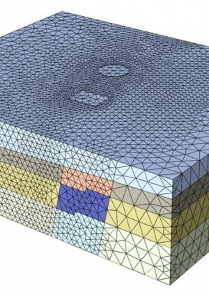
ABAQUS Version 6.12 released 2011 (Dassault Systemes Simulia Company) a general purpose finite element software package was used to perform the numerical analyses. The ground was modelled using linear tetrahedral elements and sprayed concrete linings were modelled using linear triangular shell elements. Soil materials were modelled with the elastic-perfectly plastic Mohr-Coulomb model.
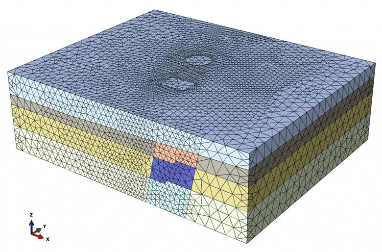
The dimensions of the model boundaries were 145m x 120m x 44m (Figure 2). The model comprised of approximately 600,000 solid elements, 50,000 shell elements and 191 analysis steps. The construction shafts (SH-W1 and SH-W2), were modelled as a wished-in-place structure following a relaxation step in which 50% of soil stiffness was reduced.
Figure 2 – Finite Element mesh and extent of the 3D model
Undrained soil parameters were taken for the analysis in order to account for the “fast” construction in comparison to the time of consolidation in the London Clay. The numerical analyses have been undertaken on the basis of a total stress analysis and no water pressure was produced during the analysis.
Ground Conditions and Model Geometry
Table 1: Ground parameters under undrained conditions, except for Upper Strata and Thanet Sand which are drained
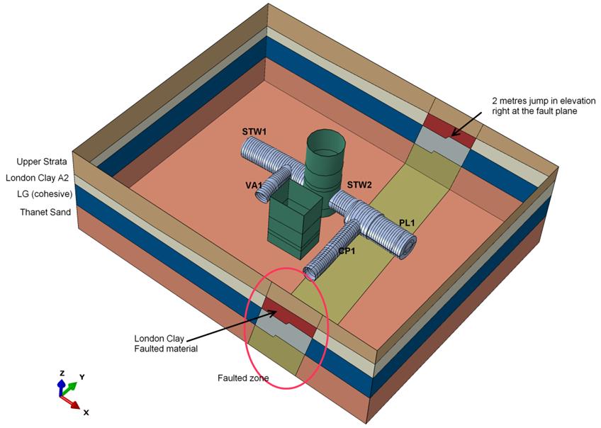
The geological formations encountered in the area of Farringdon Station, were the typical of the London basin, i.e. the upper strata comprising Made ground, Alluvium and River Terrace Deposits (mainly in the Eastern part) overlay London Clay, Lambeth Group, Thanet Sand and Chalk. In the FE model Chalk layer was considered as the bed rock and therefore the bottom boundary of the model is top of the Chalk layer. An important feature was that the thickness of the London Clay layer was significantly thinner in the western part relative to the eastern part, varying between 4 and 10m and contains London Clay A2 subdivision only. The layout of subsoil layers used in the FE model in the region around Western Ticket Hall has been illustrated in Figure 3 and soil parameters used in the FE models are given in Table 1.
Figure 3 – Fault zone and subsoil layers in the 3D FE model
The main characteristics of the geology in Farringdon station around the area subject to this FE model are the following:
- The presence of Farringdon Station Fault which affects the thickness, the elevation and the continuity of the top/bottom of the soil layers.
- The Farringdon Station Fault has been taken into account in the FE model by defining a Fault zone with faulted material properties. Boundaries of the fault zone have been obtained by offsetting ± 10 metres the fault plane identified in the geological section drawings in Geotechnical Interpretative Report. Figure 3 shows the geometry of the Fault zone in the FE model.
- London Clay contains only subdivision layer LC_A2 with a slight inclination towards west. The thickness varies approximately between 4 to 10 metres.
Steel Fibre Reinforced Sprayed Concrete Model
Table 2: Parameters for the steel fibre reinforced Sprayed concrete used in the FE models
The primary SCL consists of a fibre reinforced sprayed concrete lining. The material properties utilised for the sprayed concrete tunnel linings are given in the Table 2. For the primary lining design, the 28-days compressive strength was considered.
Sprayed concrete is modelled as elastic-plastic material. Residual strength parameters are considered in a post failure condition of the material. For instance, tension cut-off 0.4 MPa was considered for the tunnel linings based on Fibre Reinforced Sprayed Concrete material properties. The “concrete damaged plasticity model” was therefore implemented in the model to satisfy this material behaviour. It was a damage model for concrete material which assumes that the main two material failure mechanisms are tensile cracking and compressive crushing.
2D Finite Element Analysis
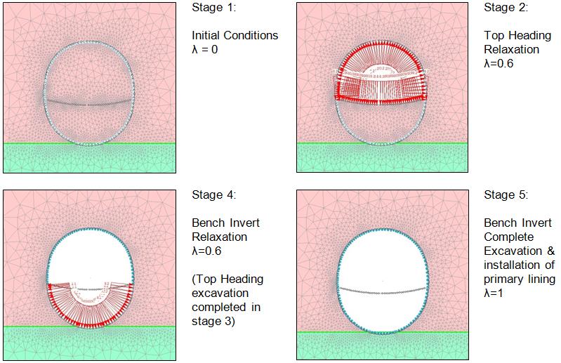
The two dimensional analysis comprised of staged, plane strain models. Construction and installation of primary lining was modelled following the prescribed predesigned excavation and support sequence. The finite element software package Phase2 Version 8.0 (Rocscience) was used to carry out the numerical analysis. The computer software analysed the ground loading conditions and ground response due to tunnel construction. The finite element mesh used consists of approx. eleven thousand 3-noded triangular solid material elements used to model the ground and beam elements to simulate the concrete lining support. The Mohr-Coulomb constitutive model was used to simulate the elasto-plastic behaviour for the elements forming the ground. The model assumes that failure occurs when the shear stress at any point in a material reaches a critical value that is linearly dependent on the normal stress in the same plane. The sprayed concrete lining in the model follows an elastic material behaviour.
Figure 4 – Typical excavation and support stages in the 2D FE analysis
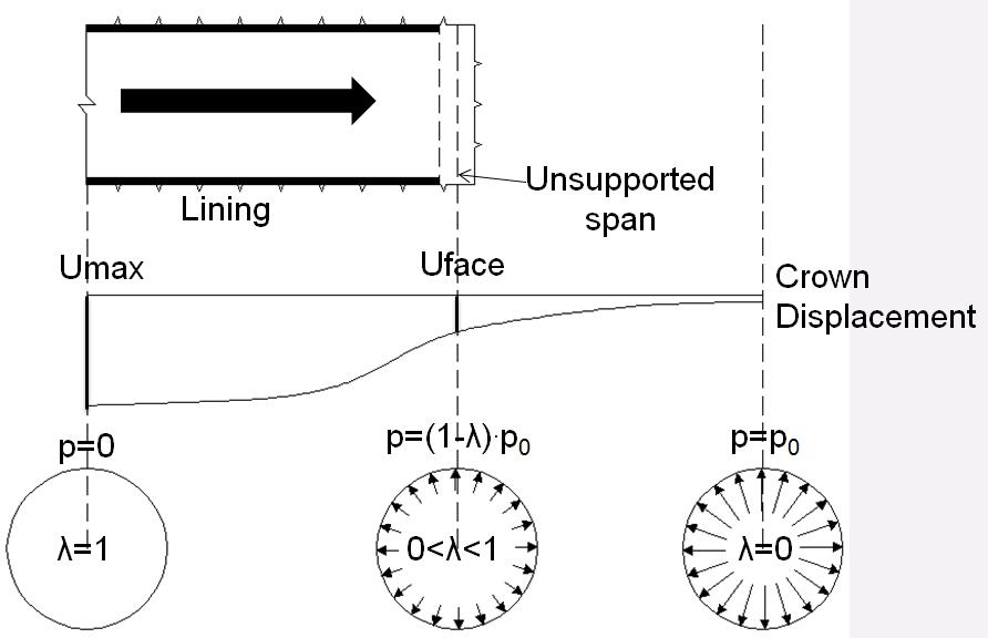
For 2D analyses, a relaxation factor or (confinement loss factor) (λ) was applied in order to simulate the deformation that took place prior to the installation of the support (Figure 5). The approach is referred to as the convergence-confinement method (Potts & Zdravkovic, 2001), to which the proportion of unloading before lining construction is prescribed and volume loss is a predicted value. Hence in the initial condition where no excavation has taken place, a value of λ=0 is applied whereas when the installation of the primary lining is complete, λ=1. The internal pressure reduction method was selected in order to simulate the ground relaxation. Hence, at all stages the internal pressure (p) applied, is a fraction of the in-situ pressure (po) that depends on the relaxation factor (λ) and is expressed by the following equation:
p=(1-λ) . po
Equation 1.
Prior to the installation of the primary lining, the pressure, p, was reduced from po (in-situ state) to (1-λ) . po, with subsequent deformation taking place. When the excavation was complete and the support system had been installed, the internal pressure aws removed (p=0)
Figure 5. Schematic of the convergence-confinement method
(Spyridis, Gakis & Bedi 2012)
A relaxation factor λ = 0.6 was used in the design of CP1, derived from an axisymmetric finite analysis model of equivalent excavation area, performed with Phase2 and later confirmed by the 3D finite element model.
During the parametric study presented in the next sections, the relaxation factor was one of the parameters that proved to have a great influence on the results, hence its value has been refined for the optimised, final analyses.
In-Tunnel Monitoring Data
Monitoring cross sections were installed in several locations along CP1 tunnel, at tunnel meters 1.1, 6.1, 18.1, 22.0, 26.2 and 30.2. For the purpose of this report, the monitoring array at tunnel meter 18.100, installed approximately in the mid- length of the cross passage was selected. Being equally distant from the breakout area (junction with PL1 tunnel) and the headwall (end of CP1), this position was less affected by end effects, hence is more appropriate for plane strain finite element analysis.
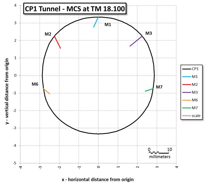
Monitoring of this cross section was carried out on a daily basis during the excavation of CP1. It has to be noted that due to the relatively small magnitude of the displacements, the results were affected by the accuracy of the readings. The final monitoring data following the completion of the excavation of CP1 are presented in figure 6. The crown monitoring point, M1, settled by approximately 7mm, as the upper side points M4 and M5. Smaller settlements were observed in the lower side points M6 and M7 (approximately 3 to 4mm). In terms of transverse displacements, points M4 and M5 exhibited approximately 5mm of inward movement, whereas points M6 and M7 moved by approximately 3mm. The 1.8mm transverse displacement at point M1 is attributed to the accuracy of the readings.
Figure 6. In-tunnel monitoring data for CP1, monitoring cross section at 18.100 tunnel meters
Optimisation of FE Models
Using the 2D and 3D finite element models of the design as a baseline, the influence of various parameters was investigated. The purpose of this study was to assess the effect that these parameters had independently on the displacements of the tunnel section and to try and derive an optimised model that exhibits similar behaviour to the monitoring section at tunnel meter 18.1 of CP1.
Parametric study on the influence of various parameters
In order to investigate the effect that each particular parameter has on the in-tunnel deformations a detailed parametric study performed in the course of the 2D and 3D FE analysis.
The main parameters that were modified were:
- the stratigraphy: (as assumed during the design stage and as observed through the excavation of CP1) – “design” was the stratigraphy used in the design models, based on the original site investigation data, “as-built” is the actual stratigraphy, as derived through the excavation of the tunnels.
- the relaxation factor, λ: a wide range of relaxation factors, varying between 0.3 and 0.8 was tested
- the parameters of the soil: during the design phase, the “faulted” parameters were used, accounting for a potential deterioration of the materials in the proximity of faults. It was however proved that CP1 was not affected by faulting, hence “unfaulted” parameters were used in the majority of the parametric analyses.
- the at-rest earth pressure coefficient, ko: the effect of ko was also investigated, carrying out analyses with values of 1.2 (design value), 1.35 and 0.65.
- the stiffness of the unloaded material: in most cases, the soil material exhibits a stiffer response when unloaded. Using a Mohr-Coulomb constitutive model, does not allow for this behaviour to be simulated. Therefore, an alternative method was used, applying an increased stiffness (3 to 5 times the original Young’s modulus – “E x 3” to “E x 5”) on a soil wedge, starting from the top-heading/bench interface, extending to the bottom of the model geometry at 45 degrees dip angle.
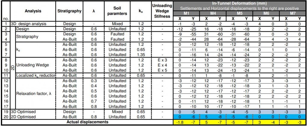
Table 3: List of the analyses performed during the parametric study and the corresponding results
Analyses 1 to 17 in table 3, constituted the framework of this parametric study. These analyses were grouped according to the parameter that was investigated:
- 1 – 2: analyses carried out at the design state using 2D and 3D finite element modelling respectively.
- 3 – 4: effect of the stratigraphy, applying either the stratigraphy used in the design analyses, or the “as-built” stratigraphy.
- 5 – 7: effect of at-rest earth pressure coefficient, ko.
- 8 – 10: effect of using higher Young’s modulus in the unloading wedge (as described above).
- 11: effect of reducing ko locally, assuming a zone of reduced ko = 0.65, around the tunnel excavation (3 radii from tunnel axis laterally) while the global ko remains at the design value of 1.2, after Potts & Zdravkovic (2001).
- 12 – 17: effect of the relaxation factor
Back analysed model results
The results of the analyses preformed in the context of the parametric study (analyses 3 to 17 of table 3), were compared to the actual displacements measured in the monitoring cross section of tunnel meter 18.1 (refer to table 3 and figure 6) and the weight of each parameter was originally assessed.
The outcome of this comparison, was that ko, the relaxation factor and the use of faulted/unfaulted parameters were playing the principle role.
Therefore, after a selection of the optimal parameters for the 3D and 2D finite element models was made, the optimised model results are presented in table 3 (analyses 19 and 20 respectively).
For the 3D model, a very good match was achieved by reducing ko from 1.2 to 0.65. For the 2D model, the optimised analysis used a relaxation factor 80%, ko of 0.65 and unfaulted soil parameters.
Conclusions
Obtained field data for the in-tunnel monitoring of the case study, cross passage CP1, were evaluated against 2D and 3D finite element models, after an extensive parametric study on the influence of various parameters.
The main conclusions of this research suggest that:
- The soil in this geological environment exhibits a significantly high relaxation prior to the installation of the primary lining. Additionally, the value of ko=1.2 that was used in the design, overestimated slightly the magnitude of the displacements, with a value of ko=0.65 providing results closer to the actual displacements.
- The use of faulted parameters for CP1 was slightly conservative, the application of un-faulted parameters proved to be more realistic in this study.
The 2D and 3D multi-parametric back-analysis above show good agreement with field data. The outcomes are very promising for future optimisation of two dimensional plain strain geotechnical models. However, its application is problem specific. The utilisation of measurements from field data and FE models reveal important aspects of the ground-support interaction applicable to the derived softening factor. The derived softening factor estimated from the axisymmetric model should require further investigation. Researching trends show a lower ko =0.65, this assessment is more representative for Lambeth Group and could be adopted for future design assumptions.
Acknowledgements
The authors would like to acknowledge the contribution of BFK joint venture for the support and the guidance towards the completion of this study, Crossrail Ltd. for the motivation and for granting the permission for this paper to get published and last but not least, Dr Sauer and Partners Ltd. for providing resources and technical support that made this paper possible.
References
Potts, D. M., and Zdravkovic?, L (2001) Finite Element Analysis in Geotechnical Engineering: Theory and Application. London: Thomas Telford, 2001
Simulia (1992) ABAQUS: User’s Manual. [Providence, R.I.]: Hibbitt, Karlsson & Sorensen, 1992.
Spyridis, P., Gakis, A., Bedi, A. (2012). Numerical Modelling. Presentation to the BTS-YM, London, October 2012.
List of notation
BFK is BAM Ferrovial Kier Joint Venture, main contractor
CRL is Crossrail, the Client and Project Manager
DSP is Dr Sauer & Partners, specialist SCL designer for BFK
FE is the Finite Element method
ko is the at-rest earth pressure coefficient
SCL is Sprayed Concrete Lining method
? is the soil relaxation factor
-
Authors
Angelos Gakis Dr. Dipl-Ing, MSc DIC, CEng MICE - Dr Sauer & Partners Ltd
Chief Geotechnical Engineer, Crossrail Farringdon Station
Ali Nasekhian, Dr-Ing - Dr Sauer & Partners Ltd
FE Design Engineer, Crossrail Farringdon Station
Stephen Flynn MSc, CEng MIEI - Dr Sauer & Partners Ltd
SCL Tunnel Engineer, Crossrail Farringdon Station
-
Acknowledgements
BFK Joint Venture, Support and Guidance
Dr Sauer & Partners Ltd, Resources and technical Siupport

