Control of Railway Induced Groundborne Noise and Vibration from the UK’s Crossrail Project
Document
type: Technical Paper
Author:
Colin Cobbing BSc(Hons), CEnvH, MCIEH, MIOA, Jo Webb, Oliver Bewes
Publication
Date: 09/07/2018
-
Read the full document
1. Introduction
The Elizabeth line will link 40 stations over 118 kilometres, from Reading and Heathrow in the west to Shenfield and Abbey Wood in the east. The new railway consists of the construction of 21 kilometres of new twin-bore tunnels, 10 new stations, improvements to 30 more and upgrades to existing rail infrastructure. The trains will be the new Bombardier Class 345, which will be over 200 metres long and able to carry 1,500 people.
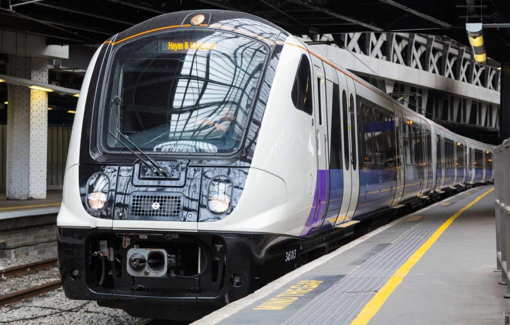
Figure 1 – Class 345 Train
The central section of Crossrail (to which this paper refers) involves the provision of significant lengths of tunnelled railway across London (see Fig.2). Crossrail operation will provide a metro style service, with a train passing approximately every 6 minutes in each direction, between 0600hours and 0030hours in the central section.
Figure 2 – The Crossrail route.
The project has groundborne noise and vibration commitments, which are intended to minimise the adverse effects on occupiers and users of the 400 buildings above the tunnels which may arise from groundborne noise and vibration generated by train services. At the detailed design stage the primary means of controlling groundborne noise and vibration from the operation of new tunnelled railways is through the selection and design of vibration isolating track systems.
1.1 Timeline
The Crossrail Act 2008 [1] contains the powers for the construction of Crossrail. During the passage of the Crossrail Bill through parliament a series of environmental requirements and assurances were negotiated and agreed with local authorities, statutory agencies, residents and businesses. Any organisation appointed by the Secretary of State to carry out the works must comply with the assurances when building the railway. These are collectively referred to as commitments within this paper.
In June 2009 The Arup Atkins Design Team were appointed to undertake the detailed design of the permanent track system as part of the route wide design of the Crossrail bored tunnels. They were responsible for producing the reference design and the engineer’s design for the floating slab track. The reference design was passed onto Alstom TSO Costain jv (ATCjv), which they subsequently adopted for the new tunnel bored sections of the new railway. Both design teams were responsible for ensuring that the design could satisfy the project’s commitments relating to groundborne noise and vibration from the operational railway.
2. Crossrail’s Commitments
2.1 Route-wide commitments
The key document containing the route-wide requirements relating to groundborne noise and vibration from the tunnelled sections of the railway is the Crossrail Information Paper (IP) D10 Groundborne Noise and Vibration [2]. IPD10 includes numerical design criteria and requirements for the design process of the track system in the tunnels.
Table 1 of IP D10, which sets out the design criteria for groundborne noise, is reproduced below. The nominated undertaker is required to design the permanent track system in the tunnels so that the level of groundborne noise arising from Crossrail near the centre of any noise-sensitive room is predicted in all reasonably foreseeable circumstances not to exceed the levels in Table 1.
Table 1 – Operational groundborne noise criteria (reproduced from IP D10).
Building Level/Measure Residential buildings, Offices, Hotels, Schools, Colleges, Hospitals, Laboratories, Libraries 40dB LAmax,S Theatres 25dB LAmax,S Large auditoria/Concert halls 25dB LAmax,S Sound recording studios 30dB LAmax,S Courts, Lecture theatres, Places of meeting for religious worship, Small auditoria/halls 35dB LAmax,S IP D10 also includes other measures to which the project has committed to reduce groundborne noise. These include:
- the use of continuously welded rail (CWR) throughout the tunnels where practicable;
- specification of a maximum combined wheel/rail roughness level;
- the conditioning of rails prior to opening and during the operational life of Crossrail to maintain the specified wheel/rail roughness level.
The key measure which is relevant to this paper is that which requires the project “to design a standard trackform for the tunnel section with the objective of meeting as many of those design criteria as can reasonably be achieved by such a standard track system and to design an enhanced trackform, such as floating slab or alternative better technology, for locations where it is predicted that the standard track system will not meet the criteria or to discharge other project commitments and undertakings”.
IP D10 also requires that additional mitigation measures should be adopted that will further reduce any adverse environmental impacts at residential properties, where the groundborne noise would otherwise equal or exceed 35dB LAmax,S. This is a more onerous design criterion than in Table 1 of IP D10. However, the requirement is qualified in that “reasonable endeavours” should be used to provide mitigation, rather than requiring compliance with the requirements in “all reasonably foreseeable circumstances”. Mitigation should be provided where “these mitigation measures do not add unreasonable costs to the project” or “unreasonable delays to the construction programme.” The implications of these requirements on the lengths of the enhanced track systems required are set out later in this paper.
IP D10 identifies that the method for demonstrating compliance with the requirements is by design, not measurement after the opening of the railway. Predictions used in the demonstration of compliance must be carried out using a model compliant with BS ISO 14837-1: 2005 [3].
2.2 Specific commitments
As well as the route-wide commitments a number of specific commitments were made to protect particular areas or facilities. For example, a specific commitment was given to protect the recording industry based in Soho. The “Soho Undertaking” (Commitment 437) covers the length of the railway between Regent Street and Charing Cross Road. Another commitment was given to preserve the acoustic conditions in the Barbican Concert Hall (Commitment 489). These can be found in the Register of Undertakings and Assurances.
3. Prediction of Groundborne Noise
A model for predicting groundborne noise and vibration from the operational railway is central to the IPD10 design process and was required to determine the type of track system required at each location along the lengths of the tunnels. A proven prediction model was taken as the starting point, and extended as explained below. The modelling was carried out using the calculation procedures developed for High Speed 1 in the UK (HS1) [4]. Since their development the procedures have been implemented and further validated on a wide range of railways worldwide (See Fig. 3).
The procedures are empirical methods developed from analytical principles, and were validated with regression analysis between measured and predicted levels of groundborne noise inside dwellings located above existing railways. Development of the prediction method specifically for the Crossrail project, as described below, enabled its application to the various types of noise sensitive property along the length of Crossrail. The HS1 method includes a term for the transfer function between vibration at the foundation and groundborne noise within a residential dwelling. For Crossrail, additional transfer functions were included for different types of buildings and foundations, using data from Nelson (1987) [5]. The estimated 95 percentile confidence limits for a groundborne noise prediction made using the HS1 procedures is +8dB. On this basis a conservative +10dB allowance for prediction uncertainty was added to all predictions to demonstrate that the design criteria would be met in “all reasonably foreseeable circumstances” inside all the noise sensitive receptors located above the tunnels.
To demonstrate that the project’s track systems would provide sufficient mitigation to meet the project’s commitments the acoustic performance of the proposed systems were modelled using the Arup Track Acoustics Model (ATAM). ATAM is a finite element model of a track which represents the train-track system as a series of masses, beams and springs.
The procedures described above were linked to Crossrail’s Geographical Information Systems (GIS) and buildings database to provide the design information needed, and to support rapid assessment of different track options at the 400 buildings above the tunnels.

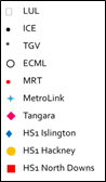
Figure 3 – Accuracy of the HS1 method for predicting groundborne noise. The datasets include measurements from London Underground (LUL), UK ; Deutsche Bahn ICE trains in Germany; SNCF TGVs in France, intercity trains on the East Coast Mainline (ECML) in the UK; Metropolitan Rapid Transit (MRT), Singapore; Manchester MetroLink; Tangara Trains, Sydney, Australia; and measurements made above the HS1 tunnels, UK.
4. Crossrail track designs
The Crossrail acoustic design process and commitments have led to four types of track system. The choice of track system for a given location was determined by the degree of groundborne noise reduction that was needed, the practicalities of installing a given type of track in that location, and reliability, maintainability and safety considerations.
As explained in Section 2.1, the commitments required that a track system be used to comply with as many of the required groundborne noise and vibration design criteria as practical. A number of railway requirements affected the final choice of track design, including the need for key track components such as resilient elements and concrete bearers to have a design life of 50 years. The standard track had to be installed at a particular rate, to enable the construction programme to be met so that the railway can open on time. Further, because of the long operating hours of the system, maintenance hours will be very limited, meaning that any rail or track component replacement must be capable of being carried out quickly.
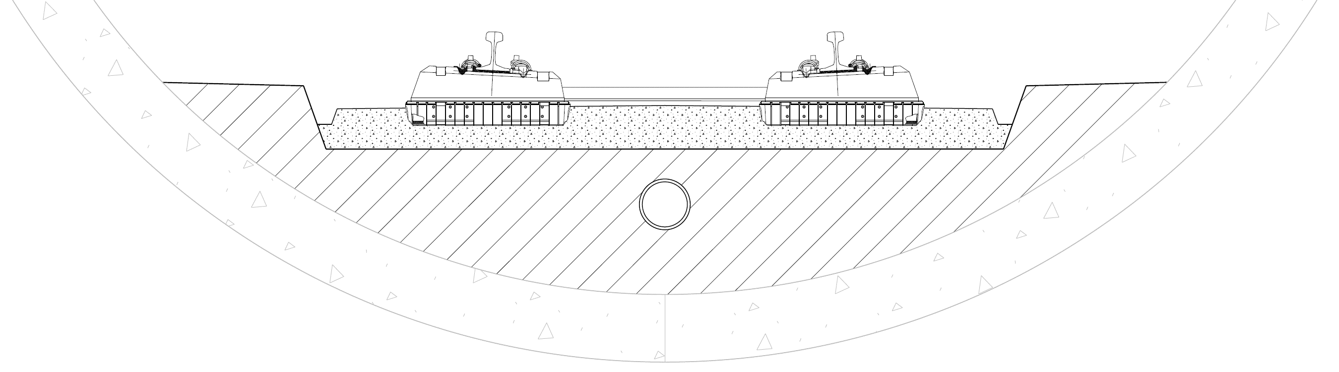
4.1 Sateba 312 CTRL V S3
Sateba 312 CTRL V S3 was installed for over 80% of the central section bored tunnels. The system comprises a precast concrete bi-block sleeper supported on resilient pads encased in rigid plastic hulls (Fig. 4). Resilience in the vertical plane is provided by an elastomeric soffit pad, with a dynamic stiffness of 10MN/m per block, which sits between the sleeper and the plastic hull. To reduce the transmission of vibration between the sides of the block and hull, six resilient pads provide resilience in the lateral plane. The pads are ribbed so that the vertical dynamic stiffness of the system is maintained under high lateral axle loading.
This system has the advantage that it provides a high level of acoustic performance and is relatively easy to install.
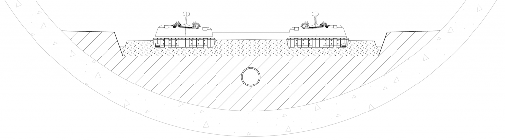
Figure 4 – Indicative cross section of the Sateba 312 CTRL V S3 track system.
4.2 Sateba High Attenuation System
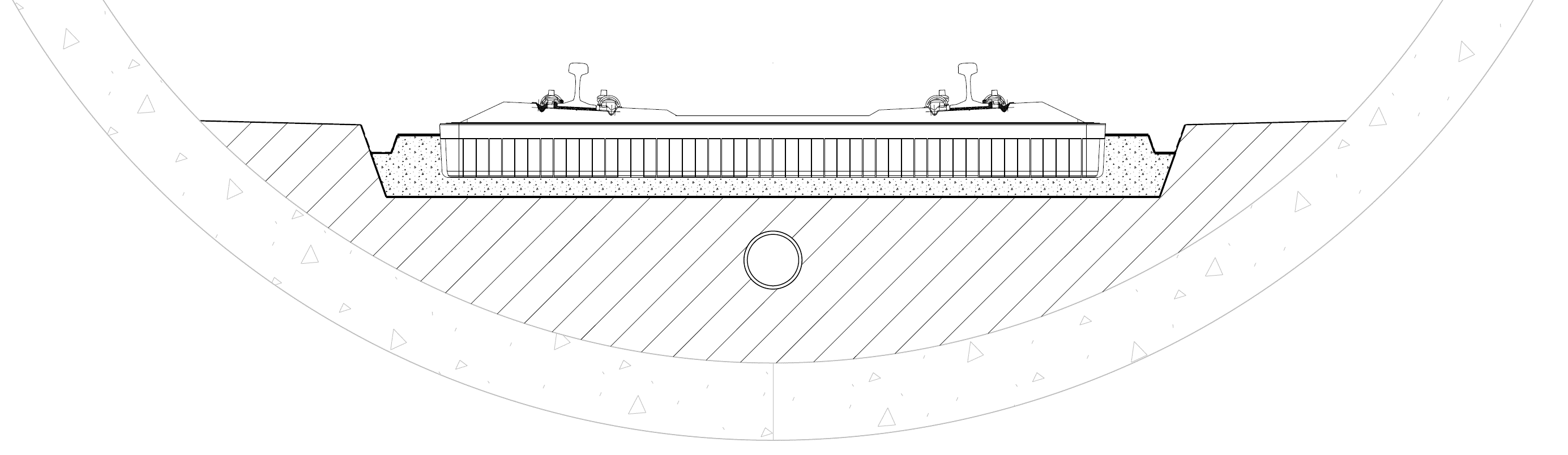
Over 3 kilometres of the Sateba High Attenuation System (HAS) was incorporated into the design, where the design criteria demanded more acoustic isolation to be used, namely a system having a lower natural frequency. Crossrail will be the first in-service use of the HAS system. The decision to use it on Crossrail was subject to a number of approvals through the project assurance system. As well as its greater level of performance, HAS can be laid at comparable rates to other track systems such as the Sateba 312 CTRL V S3 system. A cross section of HAS is in Fig. 5. The HAS is a mono-block weighing 420kg encased in a rigid plastic hull, with the hull supported by cast in-situ second stage concrete. Resilience in the vertical plane is provided by two elastomeric soffit pads, with a dynamic stiffness of 8MN/m per pad. The pads sit between the hull and the mono-block. To reduce the transmission of vibration between the sides of the mono-block and hull, six pads provide resilience in the lateral plane. The pads are ribbed so that the vertical dynamic stiffness of the system is maintained under high lateral axle loading.
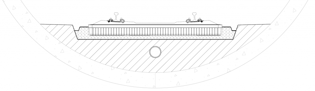
Figure 5 – Indicative cross section of the Sateba HAS track system.
4.3 Floating Slab Track (elastomer)
In order to achieve the commitment to install floating slab track in the running tunnels under the Soho area a floating slab track on elastomeric bearings design was installed. The system is a concrete slab supported on elastomeric bearings as shown in Fig. 6. The rails are supported by baseplates with a dynamic stiffness of 20-30MN/m per rail seat at 650mm centres. The rail supports are directly fastened to a floating slab with a mass of approximately 3500kg per m of track. In order to meet the required slab mass within the space constraints, an incredibly dense concrete called Magnadense was used. Magnadense has a density of more than 3400kg/m3 compared to a density of about 2300kg/m3 for the concrete used elsewhere. This higher density is due to the iron ore content of Magnadense. The slab is supported on the tunnel invert concrete layer by discrete elastomeric bearings with an equivalent dynamic stiffness of 11.1MN/m per m of track. The reinforced concrete slabs were designed with access chambers that allow installation and inspection of the elastomeric bearings.
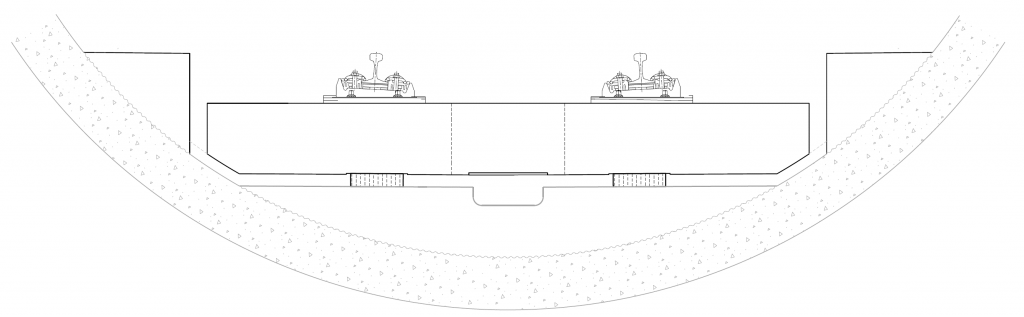
Figure 6 – An indicative cross-section of the Floating Slab Track (elastomer).
4.4 Floating Slab Track (heavy spring)
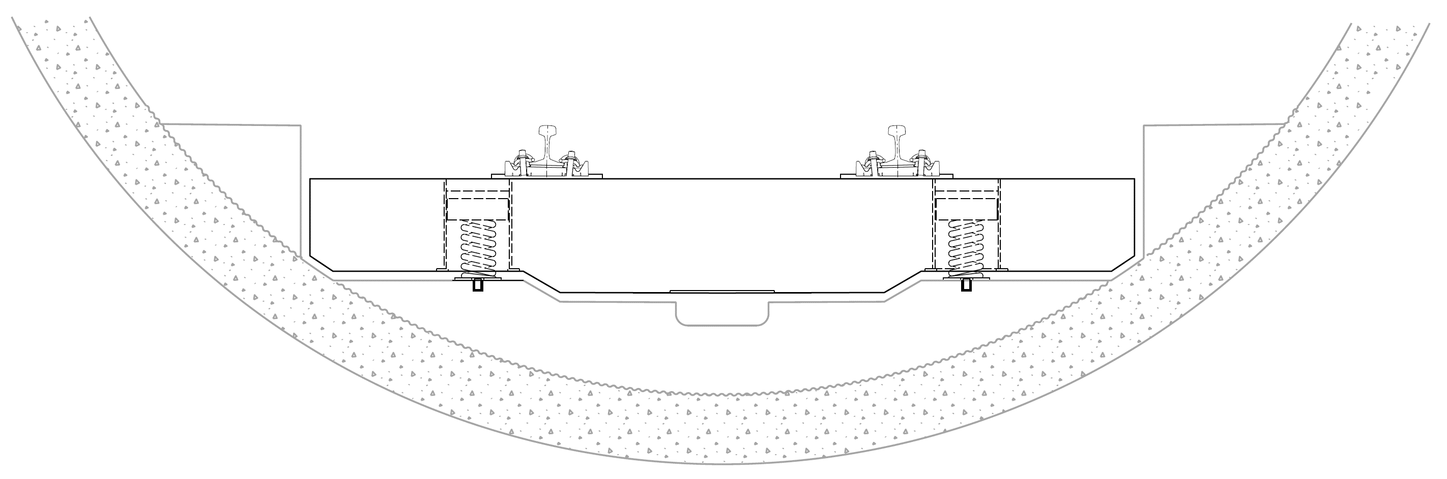
The Barbican Centre is a cultural venue with a famous concert hall, theatres, cinema, galleries and is the home of London Symphony Orchestra. The Crossrail eastbound tunnel is located directly below the building. To achieve the commitment to install floating slab track in the running tunnels under the Barbican a floating track slab with slab mass of 2875kg per metre of track and a maximum unloaded fundamental natural frequency of 7.9Hz. The specification led to the use of steel springs, which can be designed to provide a lower natural frequency than elastomeric bearings whilst meeting other design constraints. In the final design (Fig. 7) the rails are supported by baseplates with a dynamic stiffness of 20-30MN/m per rail seat at 650mm centres. The rail supports are directly fastened to a floating slab with a mass of approximately 5600kg per metre of track. The slab is supported on the tunnel invert concrete layer by discrete steel springs with an equivalent dynamic stiffness of 10.1MN/m per metre of track.
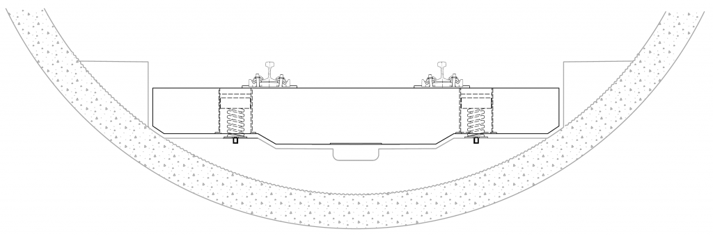
Figure 7 – Indicative cross-section of the Floating Slab Track (heavy spring).
It is worth noting that the installation of Floating Track Slab is slower than that of Sateba 312 and the high attenuation system.
4.5 Relative performance of project track systems
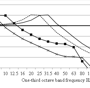
Figure 8 presents the insertion gains of Crossrail’s track systems relative to a rigid reference track. The insertion gains have been calculated using the ATAM software. The insertion gain is a measure of the attenuation and amplification, of vibration transmission to the ground relative to a rigid reference track. The frequency where the loaded track frequency occurs (the peak in the curves) is an indicator of the acoustic performance of the track system. The lower the loaded track frequency the greater the isolation at higher frequencies, and the lower the level of groundborne noise.
It can be seen that, above the loaded track frequency, the HAS track systems provides more attenuation of groundborne vibration than the Sateba 312 CTRL V S3. Because of the greater mass and lower stiffness slab supports, the floating slab track systems are predicted to provide a high groundborne noise reduction compared to the Sateba systems.
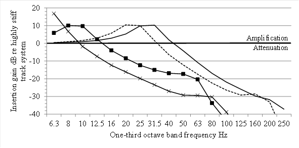
Figure 8 – Indicative insertion gains of track systems predicted using the ATAM software. Sateba 312 CTRL V S3 (▬), Sateba HAS (¬¬¬), Floating Slab Track -Elastomer (¬¡¬), Floating Slab Track – Heavy Spring (¬×¬).
5. Conclusions
The track systems in the tunnels have been designed to meet the project commitments relating to ground borne noise and vibration using proven models. These were an empirical prediction method for groundborne noise and vibration, and a finite element model for predicting the acoustic performance of the track. A conservative allowance of +10dB has been incorporated into the predictions to account for uncertainty so that the design criteria would be met in all reasonably foreseeable circumstances inside all the noise sensitive receptors located above the tunnels.
The final track installed in the central section tunnels consists of 37.8 kilometres of the Sateba 312 CTRL V S3 booted sleeper system, 2.9 kilometres of the Sateba High Attenuation System, 2 kilometres of floating slab track with elastomeric bearings and 1.3 kilometres of floating slab track with steel springs. The floating slab extents were defined by the specific commitments set out in Section 2.2. The Sateba High Attenuation System was installed in several locations to: a) address specific commitments, b) meet the criteria set out in table 1; and c) to meet the local authorities’ preference to meet 35dB LAmax,S inside residential properties.
The track designs are predicted to achieve the design requirement of 35dB LAmax,S at all residential properties located above the tunnels without imposing unreasonable costs or delays to the project.
References
[1] Crossrail Act 2008. The Stationery Office, London, UK.
[2] Crossrail Information Paper D10 – Groundborne noise and vibration. Version 4. April 2008.
[3] BS ISO 14837: Mechanical vibration — Groundborne noise and vibration arising from rail systems: Part 1: General guidance (2005)
[4] Greer R, J., Methods for Predicting Groundborne Noise and Vibration from Trains in Tunnels. Proceedings of the Local Authority Rail Impact Forum (1999)
[5] Nelson, P.M Ed., Transportation Noise Reference Book, Butterworth (1987)
-
Authors

Colin Cobbing BSc(Hons), CEnvH, MCIEH, MIOA - Arup, Crossrail Ltd
Colin has 30 years experience in acoustics. He has spent most of his career working on major infrastructure projects, spanning all different stages of scheme development ranging from: project inception, obtaining major consents, design and specification, procurement, construction, completion and commission testing. The majority of his time has been supporting promoters of schemes and contractors. He has also supported local authorities in the discharge of their planning and environmental health duties.
Colin prides himself on working openly and collaboratively with local authorities, communities and other stakeholders to reduce the scale and extent of noise impacts arising during the construction and operation of major projects.
He joined Crossrail in 2009. Prior to that he was the Noise and Vibration Manager for Network Rail on the Thameslink Programme and for the Hitchin Grade Separation Project. Between 2009 and 2015 he was Crossrail’s Noise and Vibration Manager in the Sustainability and Consents Team. In 2015 he scaled back his involvement to focus on leading the Acoustics Team at Arup. However, he still continues his involvement and is overseeing the completion of the design and installation of the Crossrail track systems in the central section.

Jo Webb
Noise and Vibration Manager

Oliver Bewes
Oliver is an Associate Director at Wood Environment and Infrastructure Solutions Limited. He has more than 15 years of experience working in the field of noise and vibration control. He is a specialist in the control of noise and vibration from railways, particularly the design of low vibration track, and has experience of the planning, design and implementation phases of major aviation, road and rail schemes. He has worked in multidisciplinary design teams delivering schemes such as High Speed 2, Crossrail, Thameslink, East London Line, London Underground and Various Network Rail schemes.