Crossrail Farringdon Station SCL Tunnels: delivering value through innovation and best practice
Document
type: Technical Paper
Author:
Angelos Gakis Dr. Dipl-Ing, MSc DIC, CEng MICE, Petr Salak Eur Ing, MSc, CEng MICE, Adrian St.John, BEng (Hons) Eur Ing FICE CEng
-
Read the full document
Notation
BFK BAM Nuttall, Ferrovial Agroman, Kier Construction (the main contractor)
DSP Dr. Sauer & Partners (the specialist SCL designer)
FBG Fibre Bragg Grating (for optical strain monitoring)
GBR Geotechnical Baseline Report
FE Finite Element
HS2 High Speed 2
LU London Underground
OCI Optimised Contractor Involvement
RES Required Excavation and Support
SCL Sprayed Concrete Lined
SRG Shift Review Group
TAM Tube-a-manchettes for Compensation Grouting
1 Introduction
Farringdon Crossrail station is approximately 300m long, stretching between the existing London Underground (LU) Farringdon and Barbican stations. The new Crossrail tunnels were constructed using the Sprayed Concrete Lined (SCL) tunnelling method. This open-face method provides unique benefits in relation to construction flexibility and adaptability to various conditions but, by its very nature, is more susceptible to geotechnical hazards. The tunnels at Farringdon, crossing multiple faults and the discontinuous sand lenses of the unpredictable Lambeth Group formations, were probably the most geotechnically challenging SCL tunnels ever to be constructed in London. Live interfaces with station box excavations and four concurrent TBM drives added further complexity to the design, sequencing, planning and logistics.
The main contractor was BFK Joint Venture (BAM Nuttall, Ferrovial Agroman, Kier Construction), who appointed Dr. Sauer & Partners (DSP) as their specialist SCL designer for the temporary works. The Client’s designer responsible for the permanent SCL works was Mott McDonald.
This paper describes the key factors that contributed to the successful completion of the SCL tunnelling works as well as the main lessons learned.
2 Station Layout and Subsurface
The station layout, shown in Figure 1, was similar to the other Crossrail stations with a total of 1km of SCL tunnels, including two long platform tunnels interconnected via numerous cross-passages, two ventilation tunnels linking the platform tunnels to the main shafts and two inclined, escalator tunnels with platform level concourses.
The tunnel lining comprised a steel fibre reinforced SCL primary lining, a sheet waterproofing membrane and a cast in-situ secondary linings also using steel fibre reinforcement. The tunnels were up to 35m below ground level with cross-section areas varying from 25m2 to 110m2.
The majority of the tunnels were excavated in the Lambeth Group, a variable formation with regards to both lithology and permeability. The SCL tunnels also encountered the London Clay and the dry Thanet Sand units, although to a far lesser extent. A description of the main units encountered during tunnelling is given in Figure 2.
Although Lambeth Group clays proved to be ideal for open face excavations, the presence of interbedded water bearing sand lenses required significant mitigation measures to ensure face stability. This was a particular issue in the Upper Mottled Beds where the water pressures were around 100kPa. In the most unfavourable sections, these sand lenses were up to 4m thick and hydraulically continuous.
To add to this already complex geotechnical context, the SCL works encountered five geological faults. The exposed face of the faulted ground was as stable as the non-faulted ground and the geotechnical properties were also comparable. However, the main impact was the vertical displacement of the sand lenses, which in the most pronounced case (Smithfield Fault) was almost 8m.
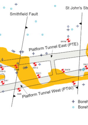
The distribution of the Upper Mottled Bed sand lenses and the location of the faults are shown in Figure 1.
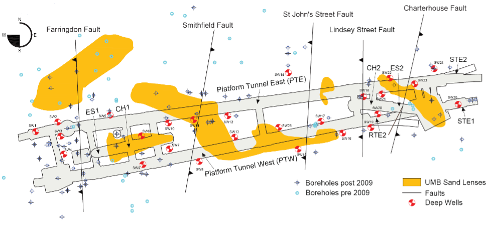
Figure 1. Plan view of Farringdon Station showing the UMB sand lenses, the faults, the boreholes as well as the Reference Design proposed deep wells
Figure 2. Description and SCL considerations of the geological units as encountered in Farrington (from Gakis et al 2015a)
3 Innovation
The BFK/DSP team carried the responsibility for all the temporary SCL works. We were not constrained by a number of Crossrail specifications for the permanent SCL works, and the team were able to test and challenge a number of conventional practices in SCL design and the Crossrail SCL permanent works specifications. Several elements that were uniquely applied at Farringdon station are discussed in the following sections.
3.1 SCL Tunnelling
Two important achievements of the BFK/DSP team at Farringdon, were the design and construction of the largest SCL tunnels ever constructed in London without a pilot tunnel, and the formation of openings in SCL tunnels without additional steel bar reinforcement or thickening of the shell.
3.1.1 Large SCL chambers without pilot tunnel
TBM reception tunnels STE1 and STE2 (see Figure 1) were two additional SCL chambers designed to receive the TBMs coming from Liverpool Street station, thus allowing the removal of the cutterheads and of the main mechanical TBM parts. The SCL tunnels were 9010mm high by 9410mm wide with a single 400mm thick steel fibre-reinforced primary SCL. Convention would dictate the need for a temporary pilot tunnel (or sidewall or temporary invert) for tunnels of this size; however, STE1 and STE2 were instead constructed with a top-heading/bench/invert sequence, providing the most efficient compromise between face stability and rapid ring closure. STE1 and STE2 were completed faster than similar size concourse tunnels (CH1 and CH2 in Figure 1), which were enlarged from temporary SCL pilot tunnels. This refinement saved 8 days on the critical path and delivered £300k in direct savings. This solution also resulted in savings of approximately 120m3 of shotcrete (28 tonnes of CO2) and health and safety benefits by eliminating dust, noise and vibration at source (through the design) because no temporary SCL had to be demolished. The successful and timely completion of STE1 and STE2 provides a new precedent that could yield far greater benefits for future similar projects. This has already been used as a reference project for the SCL tunnels on HS2.
3.1.2 Optimised openings in SCL tunnels
Openings in SCL tunnels without additional reinforcement (steel bars / mesh) or shell thickening require high-end engineering, utilising the flexural strength of the steel fibre-reinforced concrete shell. It is by no means a solution that can be applied without critical thinking and thorough independent checking. Farringdon was an example where the local conditions, the design principles and the optimised tunnel shapes allowed such optimisations to be implemented in multiple instances. One of these structures was the temporary wraparound PL2RC, presented in detail by Gakis et al (2015c). This tunnel was similar in concept and functionality to other wraparound tunnels constructed on Crossrail, yet in this instance no lining thickening or bar reinforcement was introduced. The openings to the structures were formed without any issues, and the deformations were all within acceptable limits and correlated well with the predictions.
The benefits of these optimised openings are notable in terms of both health and safety as well as in time/cost savings. The quantified savings for a single opening are summarized Table 1. For a typical station with 20 openings, the total benefit could save up to 120 days in programme duration, 90 tonnes of steel, 3000m3 of concrete, 3000m3 of excavated material and 1000 tonnes of CO2 emissions. Refer to Gakis & Salak (2016) for details.
PROGRAMME DURATION SAVINGS Excavation 1 day Fixing of rebar in invert 1 day Spraying invert up to axis and cleaning 1 day Backfill + fixing of rebar in crown 1.5 day Spraying crown 1 day Cleaning and waiting for concrete strength 0.5 day Sub-total 6 days MATERIAL USAGE SAVINGS Steel bar and/or mesh reinforcement per opening 3-6 tonnes Additional thickening – SFRC (assuming 400mm thick) ≈160m3 Additional excavation ≈160m3 ENVIRONMENTAL IMPACT SAVINGS CO2 emissions (assuming only 150 kg/tonne of reinforced concrete) ≈ 50 tonnes Table 1: Savings in programme duration, material usage and environmental impact when avoiding the installation of additional reinforcement and thickening in one opening (after Gakis, Salak (2016))
3.2 Fibre Optic Monitoring
In addition to the conventional in-tunnel 3D optical targets, Fibre Bragg Grating (FBG) fibre optic strain and temperature sensing cables were installed in tunnel RTE2 (see Figure 1). The FBGs were installed at the extrados of the tunnel and proved to be robust enough to withstand the shotcrete application. RTE2 tunnel was expected to undergo significant stress (and strain) changes during the subsequent excavation of adjacent tunnels CH2 and ES2, which were in such close proximity that the invert of the escalator ES2 was practically in contact with the shoulder/crown of RTE2.
Figure 3 shows the results for the FBG sensors which exhibited the most pronounced deformations, and this indicated a good correlation between the trend of the in-tunnel optical target displacements and the strains measured by the fibre optics. On the basis of the Farringdon study, the authors consider that FBG sensors are a viable and valuable monitoring method for SCL tunnelling, particularly if deployed with two cables per section (i.e. at tunnel intrados and extrados) and using an underground WiFi network to transfer data to the surface to avoid the need for physical signal cables which are prone to damage. This case study is presented and discussed in more detail in Salak et al (2015).
Figure 3. Vertical displacement readings and FBG strain readings
3.3 Geotechnical Risk Management and Depressurisation Design
The optimisation of the depressurisation design commenced with descoping 52 prescribed deep dewatering wells due to the uncertainty of their efficiency and the severe access restrictions (see Figure 1). In order to manage the significant ground risks related to open face SCL tunnelling in the Lambeth Group formations, a bespoke geotechnical risk management framework was implemented. This involved the collection of all previously-available and/or incoming data, detailed interpretation using a 3D Geological model (see Gakis et al (2015a)) and the illustration of the spatial distribution of these risks at several stages of the project using hazard maps (see Figure 4). Sources of incoming data were the in-tunnel probing (pre-excavation) and the mapping of the exposed face (post-excavation). The 3D Geological model that was originally developed in 2009 by the British Geological Survey (Aldis et al 2009 & 2012) was handed over to BFK/DSP and was updated daily. This process constituted a continuous cycle of risk reduction through the increasing knowledge and confidence in the ground conditions. The implementation of this geotechnical risk management framework allowed a further 70% reduction of the total quantity of in-tunnel probing.
Figure 4. Mapping of Geotechnical related Hazards at the design stage (top) and after the construction of the western tunnels (bottom) (from Gakis et al 2015d
4 Lessons Learned and Best Practice
The following section describes the main lessons learned as well as best practice examples from the execution of the SCL tunnelling works at Farringdon.
4.1 Contract and SCL design responsibility
The project benefited greatly by the use of NEC3 option C, which promoted collaboration and communication, and provided the Employer with cost transparency. The project team had aligned objectives, shared targets as well as risks, and a stake in successful outcomes. Additionally, the Geotechnical Baseline Report (GBR) provided an excellent, easy to use, objective measure of allocation of ground risks and assessment of entitlement to Compensation Events.
The combination of NEC3 Option C and the GBR provided the Employer with a competitive initial Target Price, and protection of the Contractor against adverse ground conditions and other significant risks such as interfaces and design development. In this respect, it should be of no surprise that the final out-turn cost at Farringdon was substantially higher than the initial Target Price (NCE 2019). If the Employer had wished for little or no growth in price then an alternative contract model could have been employed (e.g. fixed price lump sum), but that would have resulted in a far higher initial price and the taxpayer paying for risks whether they ultimately occurred or not. In the authors’ view, the choice of NEC3 Option C was prudent, and provided a sustainable economic model for the industry, affording appropriate incentivisation and protection for both Contractor and Employer alike. It should be recognised that projects of this scale and complexity carry extremely high commercial risks, and Contractor margins remain extremely tight.
The involvement of the BFK/DSP design team at Farringdon started with the Optimised Contractor Involvement (OCI) process, a 12-week period during which the team investigated potential optimisations of the SCL design. However, by this stage the SCL design was already at RIBA Stage D and, with the benefit of hindsight, far greater benefits might have been achieved through earlier and longer engagement.
A complex Division of Responsibilities for the SCL design was the result of the contractual framework (a ‘construct only’ contract rather than ‘design and build’) and of the utilisation of the SCL primary lining works as part of the permanent works. This posed a particular challenge to the teams because the Contractor, responsible for the temporary works, had to demonstrate that the primary lining was compliant with the permanent work requirements. The point where the design responsibility for the primary lining passed over to the Client was not clearly defined, and different approaches were followed on different Crossrail SCL contracts. At Farringdon, the primary linings transitioned from the temporary to the permanent works design following closure of the SCL inverts and achievement of the 28-day strength in the shotcrete. It is the authors’ view that future SCL projects with similar design requirements for the primary linings should employ just one SCL designer with full responsibility to avoid complexity and superfluous interfaces.
4.2 The BFK ‘TBMs first’ initiative
The platform tunnels at Farringdon were enlarged from the precast concrete tunnels which had been constructed by the TBM. Although this introduced additional interfaces, it provided an excellent TBM pilot tunnel from which in-tunnel investigation and ground treatment could be executed. This also resulted in reduced settlement, increased safety, increased productivity, and reduced HGV movements through central London. A full analysis of the benefits of this approach is given in St.John et al (2015).
4.3. SCL tunnelling in sand
Sand lenses were encountered on multiple occasions during the SCL excavation works. Although the lenses in the lower part of the Lambeth Group (Lower Mottled Beds) were depressurised thanks to historical water abstraction, the sand lenses in the Upper Mottled beds were water-bearing and too thick to excavate without implementing specific mitigation measures (‘toolbox items’).
A simple set of water inflow and pore water pressure criteria were defined by DSP which gave the site team clear actions to be taken based on simple measurements. This process was followed successfully when water bearing sand lenses were encountered, enabling rapid decision on site based on simple measurements at the tunnel face. When these criteria were exceeded, in-tunnel vacuum-aided depressurisation was utilised. In one location at the east end of the Eastbound Platform Tunnel, a 4m thick lens was encountered in and above the crown of the SCL tunnel enlargement. This posed a major risk to stability, and it was therefore decided to combine targeted depressurisation measures with chemical grout injections (sodium silicate). The latter reduced the permeability of the sand and increased the undrained shear strength, thus increasing the overall stability of the exposed tunnel face.
Additional probing was carried out prior to the restart of the SCL enlargement works to verify the successful implementation of the mitigation measures. In addition, the first SCL excavation rounds were protected by spiles, and were further sub-divided into smaller pockets to enhance face stability. Table 2 presents the main details of the in-tunnel depressurisation and chemical grouting applications.
Depressurisation Chemical Grouting Installation location Sides of TBM segments, above axis Crown of TBM segments Spacing 3m 1x1m grid Quantity 21 no. wellpoints 78 no. TAMs Length 6-12m 5m Borehole size 76mm ID self-drilled
90mm open hole
90mm ID open hole Pipe 38mm ID PVC self-drilled
25mm ID PVC open hole
40mm ID PCV (TAM), 3 ports/m, 12 ports per TAM Annulus backfill Grout seal Grout seal Drilling equipment 5T and 10T Track mounted rotary drilling rig 11T Track mounted rotary drilling rig Pump Duty and standby vacuum pumps Portable grout pump (max pressure 60bar) Screen length/type 2m long, slotted or resin-bonded filter sand – Max injection rate – 5l/min Max injection volume – 100l/port Max injection pressure – 3bar Table 2: Details of in-tunnel depressurisation and chemical grouting installations in PTE
4.4 Grouting
In addition to the chemical grouting injections, permeation and compensation grouting were successfully deployed across the Farringdon SCL works.
4.4.1 Permeation Grouting
Permeation grouting was successfully utilised for the safe excavation of the west escalator tunnel (ES1) to mitigate the risk of low cover to the permeable and variable Made Ground and River Terrace deposits, and the risk of migration of contaminated material from an uncharted buried oil tank. Two layers of 50mm diameter tube-a-manchettes (TAMs) were installed from within the escalator secant piled shaft through the unreinforced piles. The temporary works design criteria set a minimum unconfined compressive strength of the grouted ground of 300kPa and permeability less than 5 x 10⁻⁷m/s. The target volume criteria for the grout injections was 8,000 litres for a 30m3 treated block assuming 35% ground porosity and void filling degree of 75%. The assessment of the injection progress and monitoring results were presented and validated through the SRG/RES process (daily shift review group and required excavation and support meeting), and the subsequent SCL excavation works were successfully completed.
4.4.2 Compensation Grouting
More than 75% of the tunnels were covered by compensation grouting TAMs (Figure 5) for control and mitigation of ground settlement induced by tunnelling. The TAMs were up to 80m long and were installed from five temporary pre-cast concrete shafts.
Once the initial stage of calibration of grouting pressures and mix (pre-treatment) had been completed, the regular operation cycle entailed front injections (ahead of the SCL face) which aimed to pre-heave the ground, followed by rear injections (behind the SCL face) which aimed to compensate for any further settlement. A moving exclusion zone was prescribed ahead, behind and above the tunnel face to avoid adverse impact on the tunnel lining or face stability.
The actual displacements of the SCL tunnels were studied using 2D and 3D FE analyses (Gakis et al (2015b)) in order to derive the effective grouting pressures acting on the lining. The in-tunnel monitoring analysis implied an additional 2.5mm settlement of the tunnel crown point due to the compensation grouting action. The results of back-calculations showed that this additional displacement corresponded to a net grouting pressure of 200kPa (50kPa applied in 4 consecutive stages), which was far less than the grouting manifold pressures which were in the range of 1,000 to 2,000 kPa. It was additionally deduced that the effect of the front injections was to reduce the total surface settlement from 12mm (no grout) to 8mm. The remaining settlement was further reduced to almost zero with the application of the rear injections. These observations are potentially of great use for future projects, particularly when designing the tunnel linings for compensation grouting pressures or when defining the extent of exclusion zones.
Figure 5. Compensation grouting coverage at Farringdon station. The location of the grouting shafts as well as the extent of the TAMs are shown
4.5 Proximity of simultaneous SCL excavations
According to the standard Crossrail specifications, any SCL tunnels undergoing simultaneous excavation should maintain a minimum distance of 25m between closed rings. This restriction posed significant programme and logistics challenges for the Contractor due to the concurrent excavation of the Platform Tunnel East (PTE) and the adjacent concourse tunnel (CH2). Through a detailed examination of the predicted impacts using 3D FE models, it became possible to reduce this restriction to 15m without experiencing any notable interaction. As a result, the construction of the two adjacent tunnels continued unhindered and the measured deformations did not exceed any trigger levels.
4.6 Tunnel construction advance rates
As the first major SCL tunnelling project to be executed predominantly in the Lambeth Group formation, Farringdon provided useful precedence information with regards to speed of construction. The advance rates below are defined as equivalent ring metres per time unit, to take account of the excavation sequence and face sub-division of SCL tunnels.
Tunnel advance rate can be quantified either as length per time, or number of advances per time. When the excavation sequence is divided in top heading/bench/invert, as in most cases at Farringdon station, it is easier to average the advance rate in metres per day. As such, one metre per day advance rate implies an advance of an equivalent 1m long ring in one day.
The advance rate of a tunnel depends on numerous factors including but not limited to:
- Size / geometry / thickness of the tunnel lining
- Ground conditions / water pressures
- Available tunnelling plant
- Excavation and support sequence, including face sub-division
- Concrete quality / strength
- Experience of contractor/ tunnelling crews
- Pre-support / mitigation measures
- Unforeseen down time
- Workforce productivity incentivisation
An analysis of the production rates at Farringdon station illustrated the benefit of the ‘TBM first’ approach:
- Concourse tunnels CH1 and CH2, which were enlarged from an SCL pilot, were constructed at long average advance rates of 0.6 m/day (pilot 1.4m/day and enlargement 1.0m/day)
- Platform tunnels PTW and PTE with a TBM pilot, were constructed 67% faster, with a long average of 1.0m/day, (TBM pilot 15m/day and SCL enlargements 1.1m/day) as shown in Figure 6, highlighting the benefits of the ‘TBM first’ approach, in line with the findings of St.John et al (2015) for the other BFK tunnels on C300/C410.
- In the areas where the platform tunnels encountered sand lenses requiring significant mitigation measures, the advance rate of the SCL enlargements dropped locally to 0.5m/day.
Figure 6. Average advance rates in platform tunnels east (PTE) and west (PTW)
5 Conclusions
Unique innovative design methods were implemented in Farringdon Station by the integrated design and construction team in order to overcome uncertainties and risks related to SCL tunnelling in the unpredictable Lambeth Group units. The interfaces between SCL and TBM tunnelling contracts required optimal solutions to be delivered during the ongoing construction, challenging a number of precedents and established practices. This paper has summarised a number of Lessons Learned from the successful completion of the SCL tunnelling works, together with examples of good practice which will provide valuable information and new precedents for future tunnelling projects.
Acknowledgements
The authors would like to acknowledge the support of BFK Joint Venture, Crossrail and Dr. Sauer & Partners in the preparation of this paper.
References
[1] Aldiss, D T, Entwisle, D C, and Terrington, R L. (2009). A 3D geological model for the proposed Farringdon underground railway station, central London. British Geological Survey Commissioned Report, CR/09/014.
[2] Aldiss, D. T., Black, M. G., Entwisle, D. C., Page, D. P., & Terrington, R. L. (2012). Benefits of a 3D geological model for major tunnelling works: an example from Farringdon, east–central London, UK. Quarterly Journal of Engineering Geology and Hydrogeology, 45(4), 405-414.
[3] Gakis, A., Cabrero, P., Entwisle, D. and Kessler, H. (2015a). 3D geological model of the completed Farringdon underground railway station. Crossrail Project: Infrastructure design and construction. (pp. 431-446). ICE Publishing.
[4] Gakis, A., Grau, B., Schwind, T. (2015b). Tunnel Deformations caused by Compensation Grouting at Crossrail Farringdon Station. Proceedings of the World Tunnel Congress 2016. San Francisco, USA.
[5] Gakis, A., Salak, P. (2016) Efficient Design of Openings in SCL Tunnels. Tunnels and Tunnelling International, October 2016, pp. 41-46.
[6] Gakis, A., Salak, P., St.John, A.. (2015c). Temporary Sprayed Concrete Lining Tunnels in Farringdon Crossrail Station. Proceedings of the World Tunnel Congress 2015. Dubrovnik, Croatia.
[7] Gakis, A., Salak, P., St.John, A. (2015d). Innovative Geotechnical Risk Management for SCL tunnels. Proceedings of the ICE Geotechnical Engineering, vol. 168. pp 385-395. Thomas Telford, 2015.
[8] Salak, P., Gakis, A., St.John, A. (2015). A Comparison between Monitoring Solutions within SCL Tunnels at Crossrail Farringdon Station. Proceedings of the World Tunnel Congress 2016. San Francisco, USA.
[9] St. John, A., Potts, V., Perkins, O. and Balogh, Z. (2015). Use of TBM pilot tunnels for large diameter SCL caverns: the benefits, challenges and successes of Crossrail contract C300/C410. Crossrail Project: Infrastructure design and construction (pp. 207-229). ICE Publishing.
[10] New Civil Engineer magazine (NCE) (2019). Crossrail | Huge cost hikes on stations and tunnels revealed. https://www.newcivilengineer.com/latest/crossrail-huge-cost-hikes-on-stations-and-tunnels-revealed-03-05-2019/
-
Authors

Angelos Gakis Dr. Dipl-Ing, MSc DIC, CEng MICE - Dr Sauer & Partners Ltd
Chief Geotechnical Engineer, Crossrail Farringdon Station
Petr Salak Eur Ing, MSc, CEng MICE - Dr Sauer & Partners Ltd
Design Manager, Dr. Sauer & Partners Ltd

Adrian St.John, BEng (Hons) Eur Ing FICE CEng - BAM Ferrovial Kier
Adrian St.John is a Fellow of the Institution of Civil Engineers and a Supervising Civil Engineer. He has spent most of his 24 year career working on major infrastructure and tunnelling projects in the UK and overseas, including the Brighton Stormwater tunnel and High Speed 1 at St Pancras. He spent 6 years as Chief Engineer for BFK Joint Venture who were the main contractor on Crossrail contracts C300, C410 and C435, and is the Design Director for Carillion Eiffage Kier (CEK) Joint Venture bidding for the forthcoming HS2 main civil works.