Design and Construction of Crossrail Stepney Green Sprayed Concrete Lined Caverns
Document
type: Technical Paper
Author:
Nicholas Tucker Eur Ing BSc CEng MICE, Katherine Scevity BEng MCQI CQP, John Comins BEng HND ACSM, Emilio Linde BSc MSc DIC EurGeol FGS, ICE Publishing
Publication
Date: 03/11/2014
-
Read the full document
Project Description
At over 50m long, 17m wide and 14m high the Stepney Green Caverns are the largest caverns ever built using Sprayed Concrete Lining techniques in Central London.
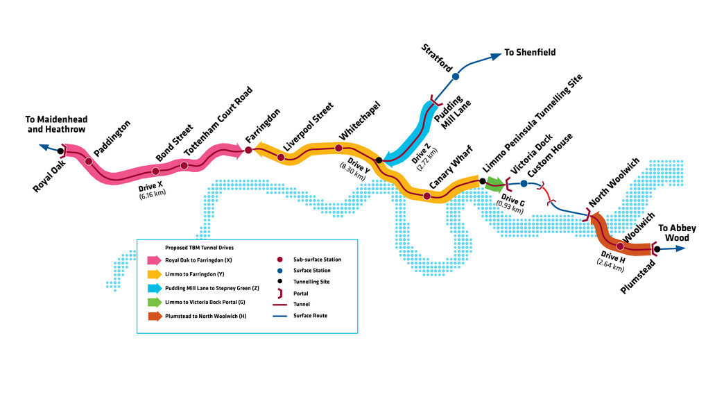
The Stepney Green Caverns were excavated under the East End of London at Stepney Green to create the underground rail track junctions on the city’s Crossrail project that will permit train services to run either north towards Stratford or south towards Canary Wharf. See Figure 1.
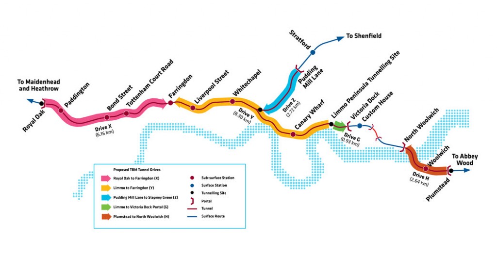
Figure 1 – Crossrail Alignment
The vertical alignments of the caverns are different; with the westbound alignment being approximately 5m deeper. This meant that the eastbound cavern was wholly excavated within London Clay whilst the westbound cavern encountered up to 4m of Lambeth Group below axis level.
Excavation of the caverns progressed from a rectangular access shaft, built across the twin TBM running tunnels to the west of the junctions that will house M&E utility rooms, a ventilation facility and provide an emergency ingress and egress for Crossrail during operation. The SCL cavern design was carried out by Mott MacDonald Ltd. supported by Gall Zeildler Consultants. Temporary works were designed by OTB on the contractor’s behalf. The caverns form part of the Eastern Running Tunnels Contract C305 that was awarded to the Dragados/Sisk JV in December 2010 for approximately £500 million.
The contractor took possession of the site in March 2010 to set up and start excavation of the large access and operations shaft. The shaft construction used diaphragm slurry walls of up to 40m deep, 15m wide and 60m long with bar reinforcement cages and over 9,500m3 of concrete. Shaft construction was completed in January 2013 and SCL excavation commenced on the EB launch tunnel in November 2012 and the EB cavern in January 2013. The EB cavern Primary Lining was completed in May 2013, followed by the westbound in August 2013. To construct the caverns and launch tunnels, the project team had to excavate approximately 38,000m3 (bulked) of material and apply over 6,000m3 sprayed concrete to the temporary and permanent walls.
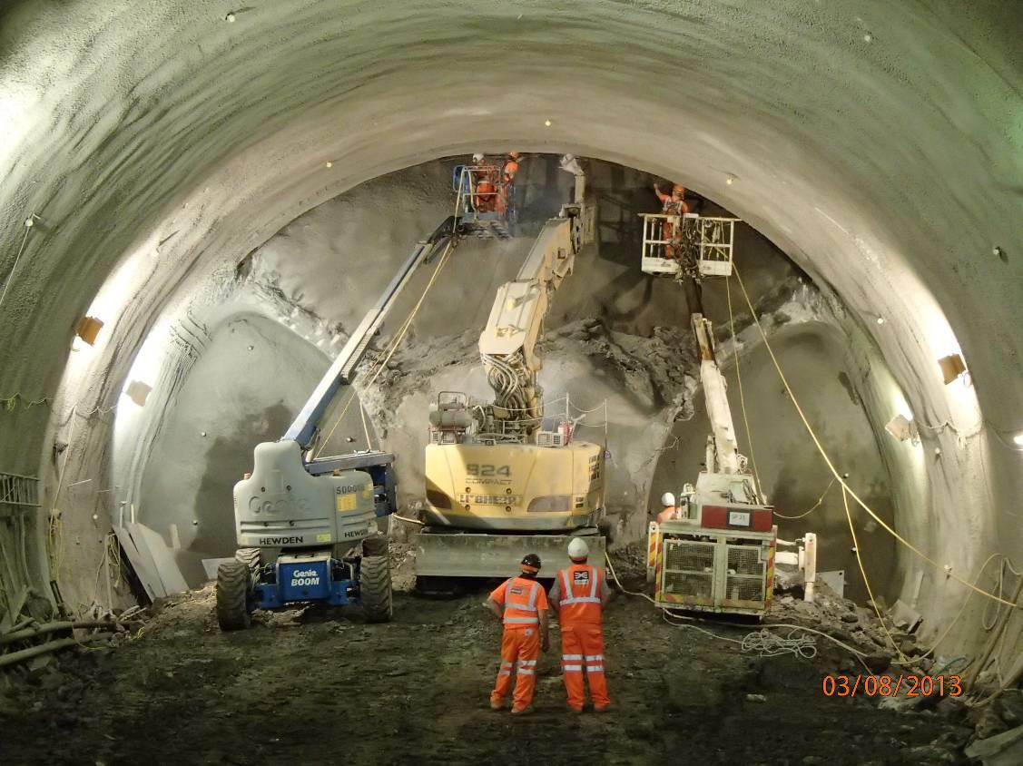
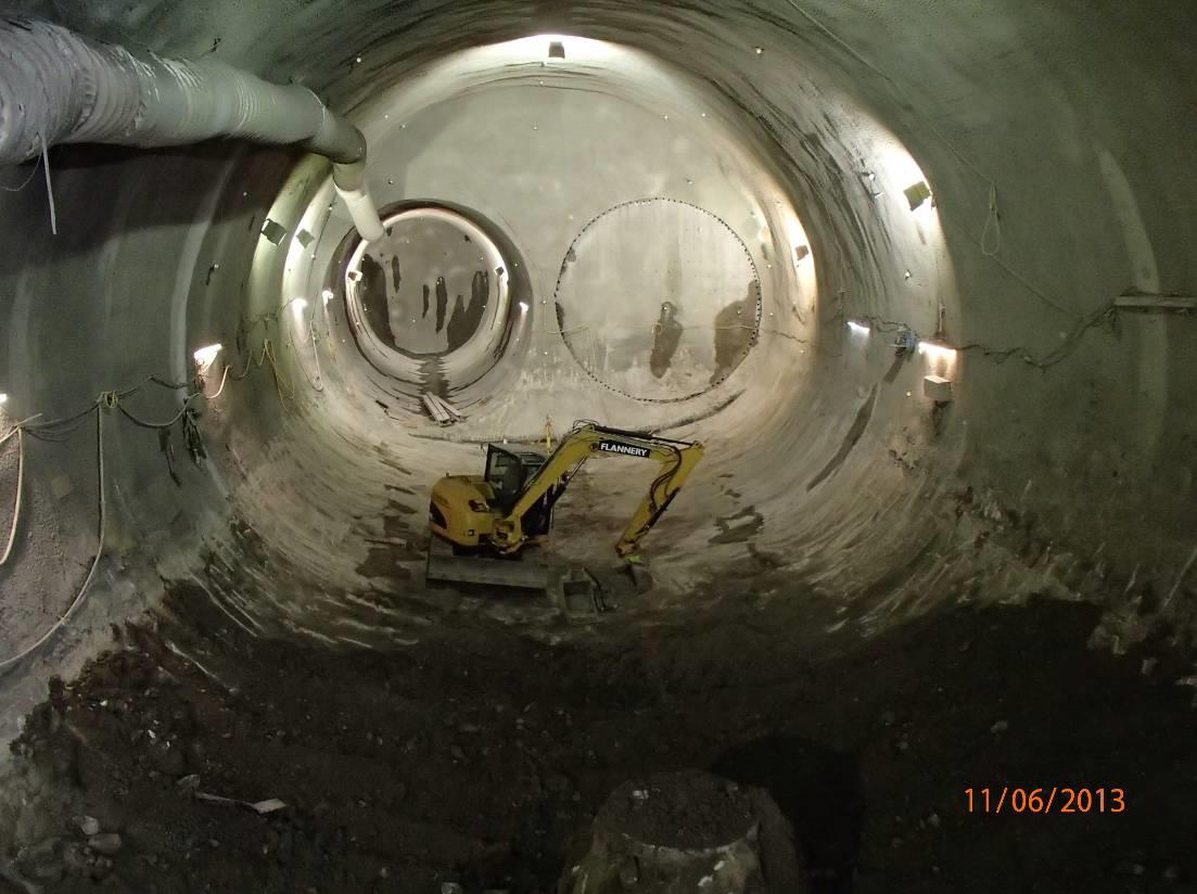
Figure 2 – Stepney Green Cavern – Primary Lining for Largest Section
Risk Management
The construction of the Stepney Green Caverns was one of the highest risks on the CRL programme. The size and location of the caverns are unique; caverns of this size had never been built in the same geological conditions in London. The risks associated with the construction of the caverns needed to be carefully managed in order to meet the Client’s and other legal obligations and followed the principles of the Joint Code of Practice for Risk Management of Tunnel Works.
The period of time when the face or crown is left unsupported was when the high risk events were most likely to occur. In accordance with the requirements of CDM legislation, the Designer identified risks that could not be mitigated during design and passed them on to the construction phase.
The main risks included;
- Instability and/or collapse of the tunnel through water ingress due to presence of sand channels
- Local face instability with block falls or collapse due to highly fissured and slicken-sided zones of clay.
- Potential for isolated pore water pressure in granular layers causing instability of excavation face and inundation.
- Unknown hydrology causing inundation of the tunnel causing drowning or injury.
- Inadequate depressurisation of non-cohesive strata leading to potential tunnel excavation instability, tunnel collapse and impact on third parties and the general public.
In order to manage these risks effectively a suite of documents, review meetings and other tools were utilised.
The SCL Action Plan was the main risk management document used by the Contractor and contained details on how to mitigate risks. The action plan described how the ground and tunnel movements, water inflows and other unexpected situations would be controlled during the works. Specific Action Plans were also developed for high risk areas of the works, e.g. for the Westbound Cavern – Groundwater and Depressurisation.
Due to the high risk nature of these works, key personnel were required to meet strict competency requirements and approved by the Client’s Project Manager. To ensure all parties were aware of the works, their responsibilities and the impact of other interfaces a suite of meetings were put in place. Namely the Shift Review Group (SRG), the Contract Technical Committee (CTC) and the Engineering Review Panel (ERP).
The SRG was held daily. Representatives from the Client, the Contractor, the Designer and the Senior SCL Engineer were required to attend the meeting. The role of the group was to review the last 24 hours of work, discuss any observations (health & safety, quality and technical), review the monitoring data, face logs, probe holes etc. Having reviewed all the data, the works for the next 24 hours were then planned and recorded on the Required Excavation and Support Sheet (RESS), acting as the permit to work system.
The CTC met bi-weekly to review the effectiveness of SRG process. Senior representatives from the Client, Contractor, Designer and the Senior SCL Engineer met to review the summary of the previous week’s progress. The meeting was also used to discuss technical issues such as excavation methodology and the effectiveness of the depressurisation system. The CTC helped manage high risk operations by highlighting areas which could be improved upon.
The ERP met every four weeks and included members from the CRL Central Engineering Group. The ERP played an overseeing role during the works. They reviewed the output of the SRG and the CTC, gathering and disseminating any lessons learnt. High risk activities undertaken on other parts of Crossrail were discussed at the ERP and any lessons learnt incorporated in to the cavern works.
The CRL Expert Panel provided valuable peer review, allowing the overall team to be questioned on the robustness of the systems in place for controlling the works. They visited the site on a number of occasions, in advance on key risk activities commencing, for which the Contractor and the CRL site team and Designer prepared presentations for discussion.
Primary Lining Analysis & Design
SCL Lining System – The lining system developed for the SCL tunnels at Stepney Green comprised a steel fibre reinforced Primary Lining, a waterproofing membrane and a non-steel fibre reinforced Secondary Lining with bar-reinforcement. The lining is a double-shell lining with both linings considered part of the permanent load bearing structure. A combination of spray applied waterproofing and sheet membrane was designed for SCL structures for Stepney Green.
Material Durability – Key performance criteria that determined the durability of the sprayed concrete material are as follows:
- Concrete mix design and reinforcement cover to meet the exposure class according to BS8500 to achieve 120-year design life.
- Water to cement ratio targeted between the 0.4 and 0.45 range to create low permeability.
- Active pozzolans, namely silica fume slurry, to further decrease the permeability to less than 1×10-12 m/s enhancing chemical stability of the concrete.
- Structural steel fibres to promote homogenous distribution of micro-cracks.
- Micro-synthetic fibres in the Secondary Lining to provide concrete anti-spalling mechanism in the event of a fire.
- Alkali-free set accelerators at dosages less than 8% by weight of total cementitious materials to promote early and long term compressive strengths.
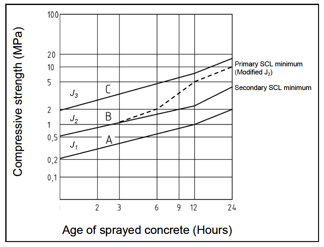
Performance Requirements – Key performance requirements for the Primary and Secondary SCL are given in Figure 3;
Performance Requirement Primary SCL Secondary SCL Design life 120 years 120 years Early age strength development (minimum) Greater than modified J2 requirements shown in Figure 4. Greater than J2 requirements shown in Figure 4. Long term compressive strength 28 days>C28/34
90 days>C32/40
28 days>C28/34
90 days>C32/40
Structural fibre performance 28 days: Class D1 S1.8 ; D3S1.4
90 days: Class D1 S2; D3S1.4
(After BS EN 14487-1)
Residual flexural strengths as for Primary SCL
Concrete shrinkage Less than 0.03% at 28 days Less than 0.03% at 28 days Exposure class DC-2 as per Table A.11 of BS 8500-1 XC3 as per Table A.5 of BS 8500-1 Water permeability (chemical durability) < 35mm penetration – See clause c) in sprayed concrete trial section of KT20.2201 Not applicable Cementitious content > 380kg/m³
Type: CEM II A-D, CII A-D
> 380kg/m³
Type: CEM I, CEM II A-D, CII A-D
Water-cement ratio < 0.45 < 0.5 Fire protection Not required Fire protection requirements to EUREKA time-temperature curve Figure 3 – SCL performance Requirements

Figure 4: Early Age Strength development for sprayed concrete – modified (based on EN 14487-1:2005)
Primary lining – the Primary Lining was designed to take the full short-term applied ground load and any other loads, such as from compensation grouting and surface surcharges, expected in the two to three years prior to Secondary Lining installation. Additional long-term loads, such as those applied through on-going consolidation of the London Clay, subsequent to the installation of the Secondary lining were shared between the two linings.
The Primary Lining comprised two layers; P1 steel fibre reinforced sprayed concrete and P2 bar reinforced sprayed concrete. Steel fibres were provided in order to increase the ductility of the concrete and provide toughness and post crack resistance in the long term. A minimum of 40kg/m³ of fibres were specified to reduce crack widths in sprayed concrete to 0.3mm. In addition bar reinforcement was provided to accommodate calculated tensile forces. Lattice girders were provided to ensure shape control and additional robustness to the design although not actually required by structural calculation.
A 75mm thick initial concrete layer, sprayed directly against the ground, was provided. This was included as load bearing in the short term but was considered sacrificial and not considered in load capacity calculations post installation of the Secondary Lining.
Secondary Lining – Taking into account the loads and stresses already taken by the Primary Lining, the Secondary Lining was designed to carry:
- The full long term water pressure,
- Internal loads, such as mechanical and electrical equipment,
- Long term load conditions; e.g. the effects of consolidation,
- The effects of temperature and shrinkage,
- Fire loads,
- The effects of degradation of the 75mm sacrificial layer,
- An allowance for additional loads that might be applied in the future.
The proportion of consolidation loading applied to the Secondary lining was calculated using FLAC numerical modelling. The Secondary Lining was reinforced with conventional bar reinforcement.
Secondary linings were designed to carry sufficient residual capacity to resist ground loading after a EUREKA time/temperature fire curve, as defined in the Technical Specification for Interoperability – Safety in Railway Tunnels TSI-SRT. The EUREKA curve was developed for the rail industry in Germany. The Secondary lining concrete (cast in-situ or sprayed) contains micro-synthetic fibres in order to limit explosive spalling and maintain structural integrity. The quantity of fibres was determined by pre-construction fire testing.
Waterproofing Systems – Waterproofing membranes were installed between the Primary and Secondary linings. The waterproofing system provided is “un-drained”; i.e. the groundwater is contained by the waterproofing membrane and not managed by an internal tunnel drainage system, the Secondary lining carrying the full hydrostatic loads.
Spray applied waterproofing membranes offer benefits by bonding to both the Primary and Secondary linings. This property offers maintenance and repair benefits in the long term by preventing the movement of water, either behind or, should it be breached, in front of the membrane. Sprayed membranes are not suitable to be applied directly to active water ingress and if this is the case sheet membranes are recommended. The Stepney Green caverns were constructed in both London Clay (sprayed membrane utilised) and Harwich Formation and Lambeth Group (sheet waterproofing membrane utilised).
Due to the presence of structural fibre reinforcement in the Primary concrete linings, a regulating layer (fine aggregate non-fibre reinforced concrete) is applied to the substrate prior to application of the waterproofing layer.
Structural Parameters – The parameters used in the design of the SCL tunnels are presented in Figure 5 below:
Sprayed & Cast In-Situ Concrete Value Characteristic compression cylindrical strength of sprayed concrete 32 MPa Mean Elastic Modulus 33.9 GPa Coefficient of creep reduction 2 Creep reduced (effective) modulus 16.95 GPa Steel Bar Reinforcement Parameters Value Yield Stress 500 MPa Elastic Modulus 205 GPa Figure 5: Structural Parameters
In order to model the beneficial effect of steel fibres in concrete sections under bending, the RILEM TC 162–TDF2 guidelines were used to model the behaviour of concrete under tension. The behaviour of concrete under compression followed Eurocode 2. This resulted in the stress strain diagram shown in Figure 6.
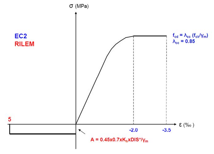
Figure 6 – Stress Strain diagram for SFRS
Where, following RILEM TC162:
- A is flexural tensile stress for ε = 0.0 – 0.5%
- A = 0.45×0.7xKhxD1S*/γm
- Kh (shape factor) = 1.0-0.6x(h-0.125)/0.475
- D1S* is 2.0 MPa at 90 days and 1.8 MPa at 28 days
The following points should be noted:
- The compressive side of the stress strain curve follows Eurocode 2 (Section 3.1.7, Figure 3.3);
- The residual strengths in tension are calculated using a simplification of the RILEM model.
- The residual strength in tension was set as a constant value up to a strain of 0.5%;
- The partial material factor of safety, γm is 1.5 for concrete and fibre-reinforced concrete and 1.15 for steel bars, in accordance with Eurocode 2.
Structural Analysis – The following numerical analyses were undertaken using both FLAC 2-D and 3-D:
- Calibration of 2-D numerical analysis to establish ground models and relaxation parameters.
- Preliminary analyses to confirm the lining shapes, thicknesses and proposed excavation sequences were structurally adequate for the Primary SCL linings.
- Modelling of ground-structure interaction using the finite difference package FLAC was carried out.
A modelling simplification inherent in 2-D modelling is the relaxation of the ground ahead of an excavation face, a largely 3-D effect, and the values used in the 2-D modelling were calibrated against 3-D models and previously constructed tunnels in London Clay, at Heathrow Airport and Kings Cross Station. Time dependent development of sprayed concrete strength and stiffness were included in the models.
In line with London Underground (LU) requirements a surcharge loading of 75kPa was applied to both the Primary and Secondary Lining cases. The train loadings were included in accordance with LU Engineering Standard 1-052 – Civil Engineering – Bridge and Railway Group Standard GC/RT5112.
Excavation Modelling – A FLAC a 3-D extruded model was used to analyse the Stepney Green Caverns. A typical excavation sequence is described below;
The narrower section of the turnout caverns utilised a single sidewall drift construction methodology. The advance lengths were 1 metre for top heading and bench and 2 metres for invert. The following construction sequence was assumed in the analysis;
Sequence Number Construction Sequence (assumed in design)
01 Construct whole length of left hand side 02 Construct whole length of right hand side Part of lining Activity Advance length (m) Duration (hours) (1) Left hand side TH Excavation, scanning, mapping 1.0 4.0 Primary lining 4.0 BCH Excavation, scanning, mapping 1.0 2.0 Primary lining 4.0 INV Excavation, scanning, mapping 2.0 4.0 Primary lining 6.0 (2) Right hand side TH Excavation 1.0 4.0 Split 1 initial lining 200mm 2.0 Sidewall removal 4.0 Primary lining incl. joint formation 6.0 BCH Excavation incl. removal of sidewalls 1.0 6.0 INV Excavation incl. removal of sidewalls 2.0 8.0 Primary lining incl. joint formation 8.0 Advance rates / cycle times
The excavation sequence is shown diagrammatically in Figure 7 taken from the 3-D model output;
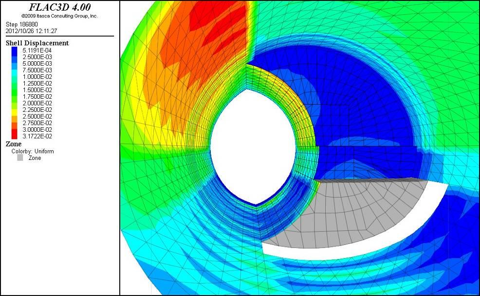
Figure 7 – Excavation Sequence for Single Sidewall Drift – showing Shell Displacement
The calculated volume losses were in the order of 1.0–1.2 %. The maximum predicted displacement for this section was 32mm.
The results of the analysis for long-term condition for the Primary Lining bending moments in the hoop direction are shown in Figure 8.
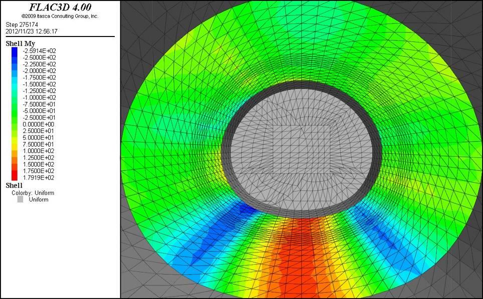
Figure 8 – Bending Moments in Long-term Condition
The red/orange colour in the invert shows tension on the inside face. The green/blue colour shows tension on outside face, with the largest moment typically being at the knees.
The wider section of the turnout caverns utilised a double sidewall drift with central gallery construction methodology. The advance lengths were 1 metre for top heading and bench and 2 metres for invert. The following calculation steps for the central gallery were assumed in the analysis;
Calculation Step Scheme Description Stage 1 Top Heading – Split 1 – Excavation Stage 2 Top Heading – Split 1 – Initial lining 200mm
Top Heading – Split 2 – Excavation
Stage 3 Top Heading – Split 1 – Sidewall removal
Top Heading – Split 2 – Initial lining 200mm
Stage 4 Top Heading – Split 2 – Sidewall removal Stage 5 Top Heading – Primary lining 625mm
Bench – Excavation
Bench – Sidewall removal
Stage 6 until Stage 10 – As Stage 1 until Stage 5 (second advance) Stage 11 Invert – Excavation and Dewatering Stage 12 Invert – Primary lining 500 mm
and again Stage 1 (third advance)
The calculated volume losses were in the order of 1.3–1.4 % for the sidewall drifts and 1.0 for the central gallery. The maximum predicted vertical displacement at cavern crown was 60mm.
Construction of Cavern Primary Linings
Ground Stabilisation and Depressurisation
As identified during the design stage, the main ground hazard during the construction of the SCL works at Stepney Green was the presence of high pore water pressures in the sandy layers of the upper part of the Lambeth Group. In the Eastbound Cavern, which was fully excavated in the stiff clays of the London Clay and Upper Mottled Beds, this pressure could lead to heave of the base and consequently rupture the impermeable clay layer during the invert stage. In the Westbound Cavern, where sand layers were encountered at bench and invert stages, the pore pressures could cause instability of face and invert due to running liquefied sands.
Based on the results of pumping tests, a surface ejector scheme was developed to dewater the upper part of the Lambeth Group. The strategy was to encapsulate the tunnels within a ring of ejectors. A spacing of approximately 8 metres was initially set by WJ Groundwater during their design based on previous pumping test data and the constraints imposed by surface access. These constraints required the use of inclined ejectors to achieve the drawdown outside the site boundaries. The dewatering layout is shown on Figure 9.
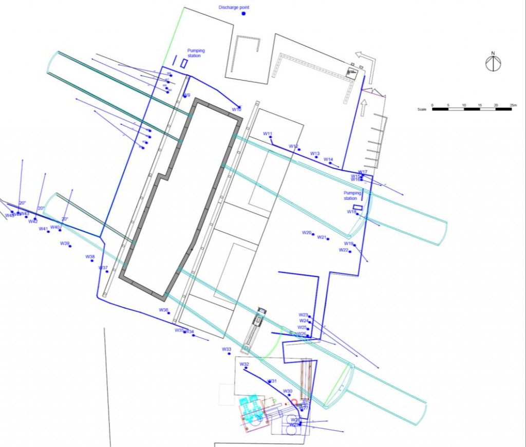
Figure 9 – Layout of Dewatering Scheme
The drawdown achieved by this surface based system was approximately 12m (from 90m to 78m ATD). As the deepest invert excavation level for the Eastbound and Westbound was 79m and 75m ATD respectively it was concluded that an additional in-tunnel dewatering system would be required for the Westbound Cavern excavation.
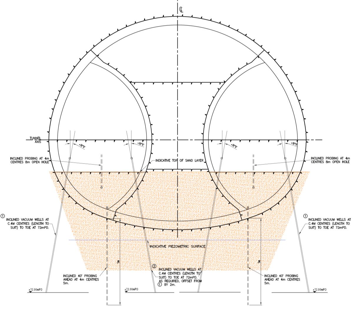
The nature of the layers to be dewatered (being randomly distributed sand channels with changes in thickness, length and frequency) meant that an intense probing regime was needed to detect these formations. A preliminary design for the in-tunnel dewatering was developed as a starting point, with wells drilled every 4 metres at bench level after the excavation and completion of the primary lining in the invert. The depressurisation worked as a temporary “moving front” of depressurisation with the tunnel wellpoints installed as the excavation progressed. The performance of the tunnel wellpoints was monitored using un-pumped wellpoints as stand pipe piezometers. This allowed the monitoring location and pumped wellpoints to be altered to suite the progress of the works. In addition dedicated piezometers, comprising shallow wellpoints, were installed to just 1 metre below the invert. See Figure 10.
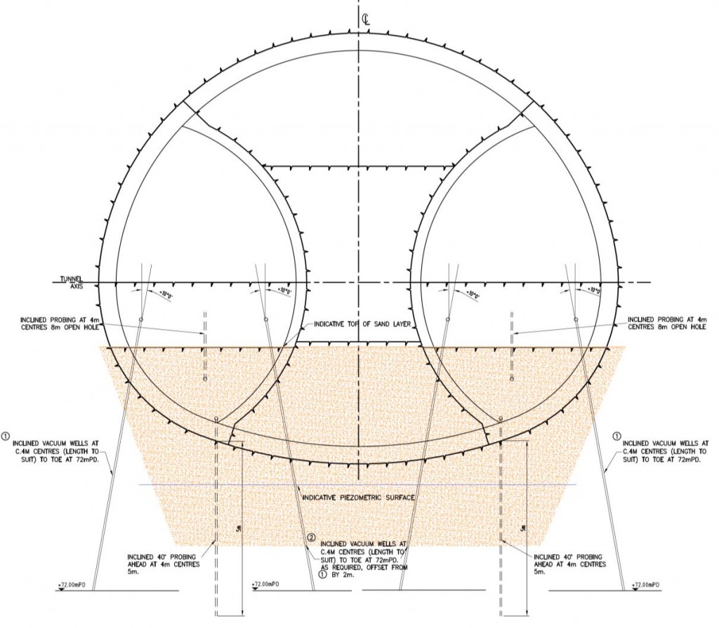
Figure 10 – Layout of Dewatering Wellpoints
Due to the inconsistent distribution of the sand layers, the initial wellpoint layout and frequency were altered following review of information obtained from the probing, face logs and piezometer monitoring. The selection of screen and filters for the wells was modified to accommodate the changes in permeability of the sand lenses with due consideration to the groundwater abstraction flow rate.
The additional drawdown obtained by the surface wells was sufficient for the excavation of most of the tunnels. However, it was not always possible to achieve a full drawdown at the interface boundary between a sand horizon and underlying clay stratum. Flowing water was sporadically encountered leading to challenging construction conditions when invert excavations were “open”. A permit to dig system was successfully implemented which ensured certain key checks had to be undertaken before excavation of the invert was permitted. The permit was signed by all of the interested parties and the Senior SCL Engineer indicated the contingency measures that had to be employed depending on the water levels and geology.
Excavation Sequence and Ground Support
Three gangs were mobilised in November 2012 to work the 24/7 shift pattern of 7 days on – 3 days off dayshift and a 7-4 nightshift. At peak times, during concurrent construction of both EB and WB Caverns, over 80 staff and operatives worked at site on each shift.
The EB launch tunnel, situated wholly within the relative “comfort” of the London Clay, was excavated first to familiarise the crews and create more working space at the pit bottom for manoeuvring the large SCL plant before breaking out through the diaphragm wall for the EB cavern. The primary excavation and spraying plant were proved during this juncture and bespoke on-the-job training was given to the crews by the suppliers and manufacturers of the plant.
The invert and crown joint connections for the lattice girders and steel reinforcing bars on the first side drift to the adjacent enlargement proved to be particularly challenging to construct. Despite best efforts during preparation of the joints some remedial works involving the breaking back of previously sprayed concrete proved to be necessary. The acute angle of each joint in section profile proved difficult to excavate and spray accurately in the close confines of the side drift. Lessons learnt from the first side drift in the EB tunnel led to a series of improvements in joint preparation that were quickly implemented in the subsequent double side drift section and the WB Cavern.
The following plant was used to construct the SCL caverns:
- Primary excavation of all tunnel elements by a pair of Liebherr 924 compact excavators c/w various hydraulic tools including Wimmer drilling units, crusher pincers, road-header, breaker, claw & various excavating buckets;
- Pair of Liebherr 928 loading shovels for removal of spoil from face into skips at pit bottom;
- Five Utranazz 5.5m3 car-mixers for conveying fresh concrete from site batch plant to column skip on surface and from pit bottom to the face;
- Primary concrete spraying by three Meyco Potenza spraying mobiles (one for maintenance as spare);
- Two Meyco Suprema shotcrete pumps and two Meyco Oruga spraying robots;
- Meyco Piccola and GM dry bag hand spraying equipment;
- L2C Atlas Copco twin boom drilling jumbo for installation of spile bars, vacuum wellpoints, ground probing and pre-split holes within Drive Y tunnel eyes of headwall;
- Combination of RT 4WD Genie boom-lift MEWPs and two tracked boom-lifts for all working at height activities.
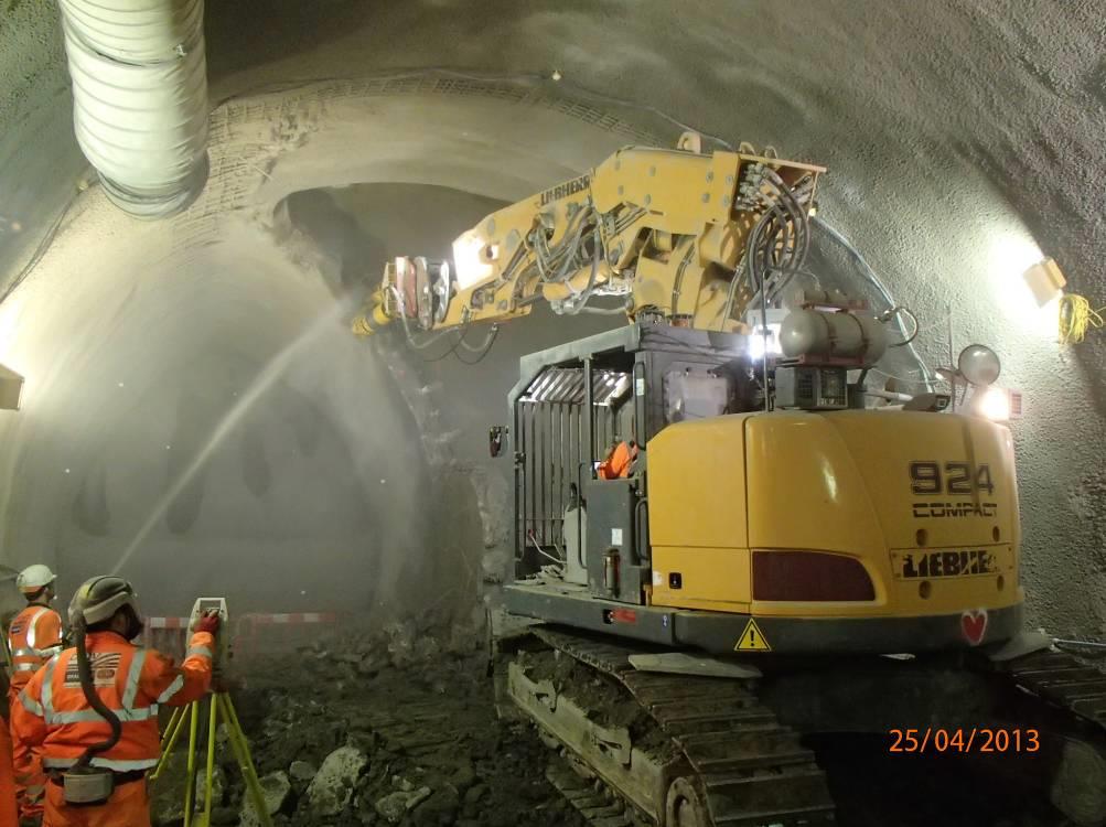
Figure 11 – EB Cavern – Removing temporary sidewall of top heading
A dedicated SCL Plant Manager was appointed to ensure that the equipment was utilised as much as possible. Prestart checks, daily maintenance and cleaning of each item of plant by the responsible trained operative were incentivised by the implementation of a production bonus scheme. Preventative maintenance and reactive repairs as necessary were carried out underground by fitters on each shift. Equipment was removed from service for scheduled maintenance by manufacturers and specialist plant technicians.
Design Development during Construction
In order to improve the constructability of the design the following early changes were agreed with the Contractor, CRL and the Designer and implemented on site:
- Bench excavation rounds for side wall and enlargement increased to 2 metres to improve speed of ring closure;
- Lattice girders were removed from all temporary side walls to minimise handling and erection risks and improve quality of the sprayed concrete lining;
- Alternate lattice girders were removed from Primary SCL main outer shell to provide girders at 2 metre centres;
- The P2 layer (comprising bar reinforcement but no steel fibres) for invert, bench and top-heading was constructed directly after the P1 layer invert in 2 metre long sections to minimise mesh lap joints and improve the quality of the sprayed concrete lining;
- The P2 mesh in main outer SCL shell at the crown and invert of the side drifts was left exposed for 1 metre to enable a better lap connection later during the enlargement construction;
- Split face construction and 200mm capping of the initial SCL layer on the top heading in larger spans of cavern central enlargement (i.e. wider sections of the apple core) was replaced by driven steel spile bars and a 75mm initial layer. This facilitated installation of the lattice girders and reduced further construction joints in the P1 layer
Tunnelling Progress
The average tunnelling rates achieved for the tunnel elements were as follows:
Tunnel Element Sequence of construction Eastbound
(m/day)
Westbound (m/day) Launch tunnel 1 1.7 0.9* Single side drift section (Cavern 1) LH side drift 2 0.9 1.3* RH enlargement 3 1.3 1.4* Double side drift section (Cavern 2) LH side drift 4 1.4 0.9* RH side drift 5 1.1 1.0* Central enlargement 6 0.6 0.8* TBM Reception stub tunnels Stub tunnels 7 1.5 1.5* * includes installation of vacuum well-points for groundwater depressurisation
The average cycle times that were achieved for the single side drift sections were as shown below;
Part of lining Activity Advance length (m) Actual Duration (hours) (1) Left hand side drift TH Excavation, survey, ramping 1.0 1.5 Primary lining (P1 only) 3.2 BCH Excavation, survey, ramp removal 2.0 2.5 Primary lining (P1 only) 2.5 INV Excavation, survey, backfill out 2.0 3.5 Primary lining (P1 only) 4.0 P2 P2 layer for INV, BCH & TH 2.0 7.5 (2) Right hand enlargement TH Excavation, survey, ramping & removal of sidewall 1.0 2.0 Primary lining (P1 only) 2.7 BCH Excavation, survey, ramp & sidewall removal 2.0 2.8 Primary lining (P1 only) 2.2 INV Excavation, survey, backfill & sidewall removal 2.0 3.2 Primary lining (P1 only) 3.2 P2 P2 layer for INV, BCH & TH 2.0 6.5 
Figure 12 – WB Cavern – Installing Lattice Girders in TH of Central Enlargement
Generally the SCL caverns were constructed faster than expected. It is considered that this was attributed mainly to:
- High motivation of work crews (mainly due to bonus pay);
- Design development during construction;
- Synergy and collaborative working between DSJV, OtB, Crossrail, C121 site teams and Designer as evidenced during the effective daily SRG and weekly CTC meetings;
- Good care, maintenance & rotation of equipment;
- Implementation and continual improvement of effective ground dewatering systems;
- Consistent supply of fresh quality concrete from the Hanson on-site batching plant;
Lessons Learnt
The main lessons learnt, relating to health and safety, have been identified as follows:
- Minimise manual hands-on work where personnel must enter the exclusion zone at the face (e.g. for joint preparation and installation of steel continuity bars, lattice girder connections, survey instrumentation);
- Minimise the duration of time that people have to be within the exclusion zone at the face for each round;
- Promote fully mechanised work where possible for joint preparation, excavation & spraying. Selection of plant and tools is an important contributing factor when planning and designing the works. Consider size, weight, power, gradeability, reach, emissions and engine fire suppression. Where possible time should be allowed for trialling each item of plant;
- Provided good shape control can be maintained by other means, remove lattice girders from the design due to the various manual handling, working at height and falling objects risks associated with their transport, handling, hoisting and erection at the face. They slow ring closure, increase potential for voids in the lining at the butt plate connections and their fixed position pre-determines face size and round length leading to an inflexible design when considering face support. Due to the flaring and changing shape of the cavern each girder had to be uniquely designed, fabricated and installed in pre-determined position.
- Minimise the use of steel bars and mesh by utilising steel fibres where possible. The bars tended to increase potential for shadowing and voids when spraying mechanically using robots;
- Avoid tight corners in the SCL profile (e.g. where the temporary sidewall meets the main outer lining shell in the crown and invert) as they are difficult to excavate and spray accurately using mechanised means;
- Use 2 metre advances for bench and invert as they create better access for excavation and spraying, minimise handling of backfill for ramping and generally enable quicker ground support and reduced ring closure time;
- Minimise construction joints that require preparation, rework and inspection;
- Remove pressure cell instrumentation from the lining as it takes time to install and read, and the results proved to be inconsistent. Other means such as strain monitoring should be considered to supplement the deformation monitoring.
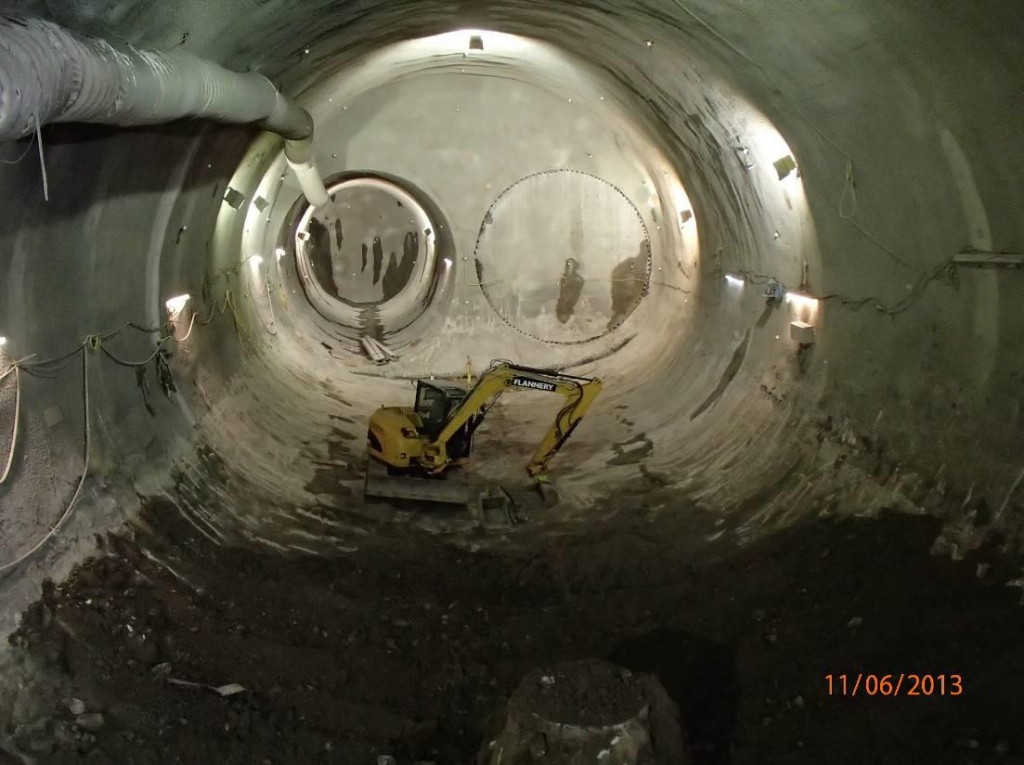
Figure 13 – Removing Backfill from Stepney Green Cavern
SCL Performance
Instrumentation & Monitoring Plan
In line with the CEDS Instrumentation & Monitoring Standard; Green, Amber & Red zones were identified as below;
The definition of the zones and trigger levels with associated actions are described below;
- Clear Zone – the zone when monitoring was initiated, prior to any triggers being reached. No actions.
- Green Trigger Level – this trigger alerted that the Green Zone had been reached. The Green Trigger level was set at 75% of the FLAC calculated lining displacement. This took account of an estimated 25% lining displacement occurring prior to installation and first reading of a monitoring point. The action was to review instrumentation and increase frequency if necessary and agreed at the SRG.
- Amber Trigger Level – this trigger alerted that the Amber Zone had been reached. The Amber Trigger level was set at 105% of FLAC calculated lining displacement. The action was to inspect the area of the relevant tunnel and review by the ERP both within 24 hours. The ERP could recommend changes to monitoring and construction methodology.
- Red Trigger Level – this trigger alerted that the Red Zone had been reached. The Red Trigger level was set at 150% of FLAC calculated lining displacement. The action was to stop the tunnelling process and make the excavated face safe pending an Emergency Engineering Review within 4 hours.
Predicted vs. Actual Lining Displacements
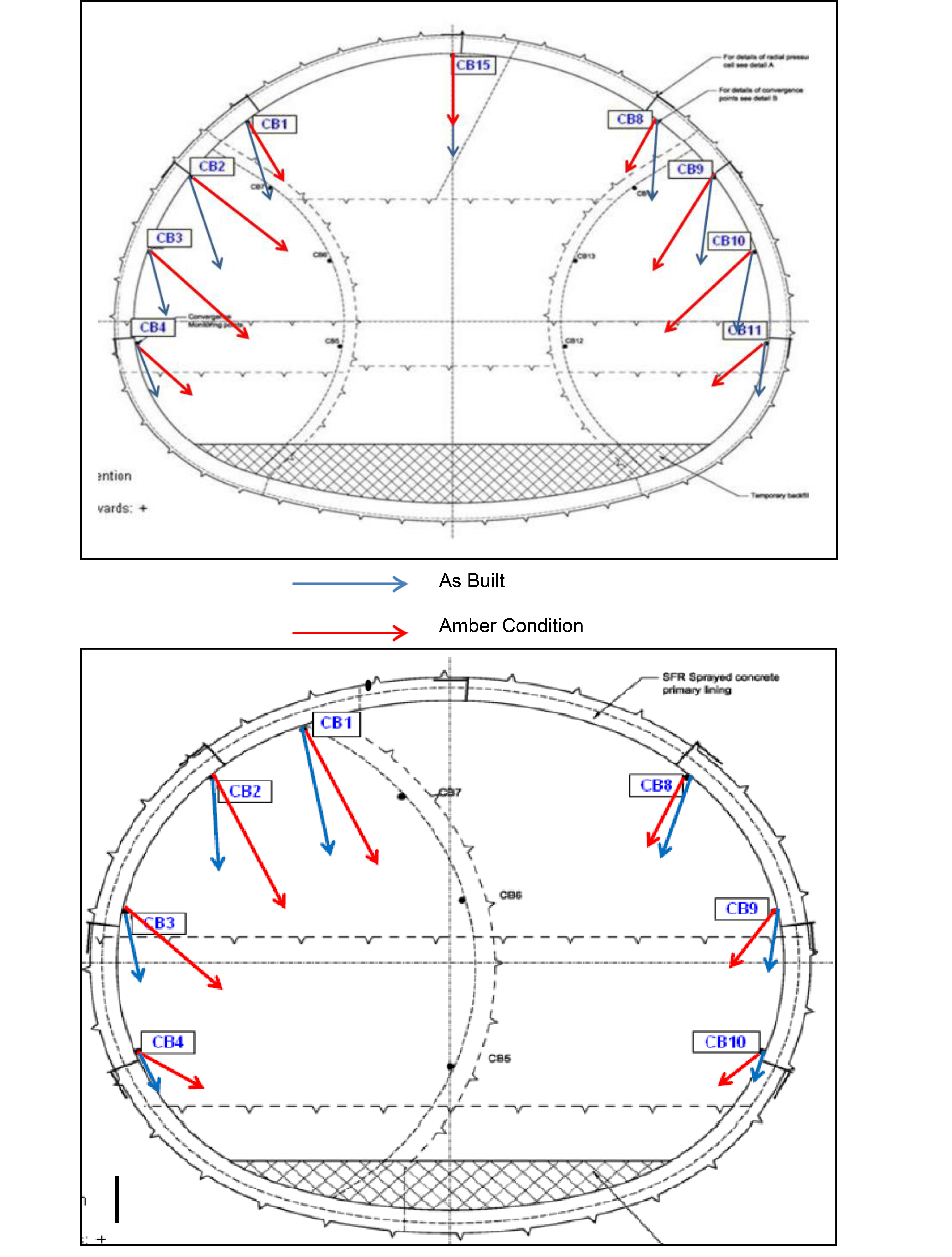
Given the variable diameter of the cavern, the Designer provided two sections for trigger level monitoring points for the caverns. In each section each monitoring point had its own set of trigger values for both horizontal and vertical deformation.
In general terms, it was observed that the vertical component was similar to the expected one (between 90% and 105% of the amber trigger value), whereas the horizontal component was less than expected (between 30% and 70% of the amber trigger value).
The following tables summarise the green, amber and red trigger values and the average values obtained;
SINGLE SIDEDRIFT SECTION Actual Horizontal Actual Vertical CB1 -0.8 10 14 20 -25.8 -21 -29 -41 CB2 -0.6 11 15 22 -19.4 -19 -26 -38 CB3 -0.5 14 19 27 -15.3 -13 -18 -26 CB4 -1.4 9 13 18 -8.6 -6 -8 -11 CB8 0.6 5 7 10 -18.9 -11 -15 -21 CB9 2.0 7 9 13 -14.1 -9 -13 -18 CB10 3.0 6 8 12 -7.2 -5 -7 -10 DOUBLE SIDEDRIFT SECTION Actual Horizontal Actual Vertical CB15 – -24.0 -13 -19 -27 CB1 -5.4 5 8 11 -20.3 -11 -15 -21 CB2 -7.3 16 22 31 -24.4 -21 -29 -42 CB3 -4.0 17 23 33 -17.2 -16 -23 -32 CB4 -9.6 9 13 19 -13.8 -9 -13 -18 CB8 2.7 5 7 11 -21.1 -10 -14 -20 CB9 7.4 10 14 20 -23.1 -18 -25 -36 CB10 4.1 14 20 28 -21.0 -15 -21 -30 CB11 4.8 8 12 17 -13.8 -8 -11 -16 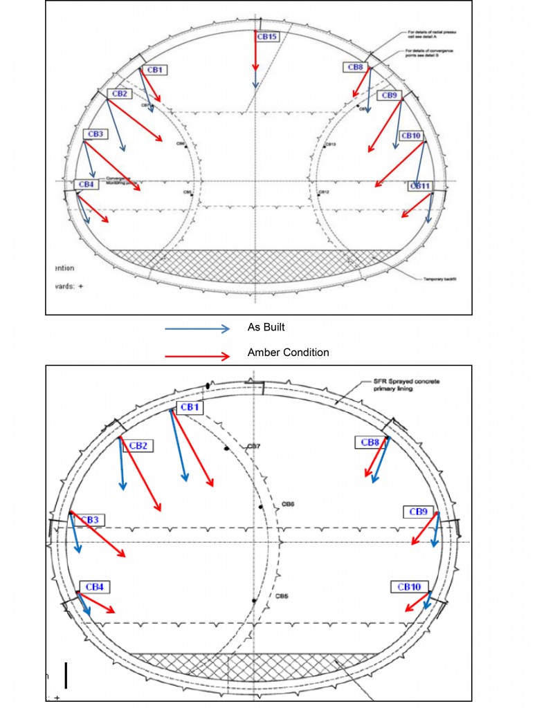
Figure 14 – The expected movement in amber condition and average as-built movement for the single and double side-drift sections.
The discrepancy between vertical and horizontal is considered to be due to the effect of the dewatering that was carried out in the sandy layers beneath the tunnel invert, causing whole-body downward movement of the cavern shell.
Surface settlement
Surface movement was monitored with several arrays of precise levelling points. Readings were taken on a daily basis. Maximum settlement was 60mm above the largest section of the Eastbound Cavern. This value includes the movement due to the SCL works and dewatering. From the analysis of the timeline in settlement, a value of approximately 10mm was determined to be related to the depressurisation and 50mm due to SCL works. The predicted surface settlement, assuming a volume loss of 1.5% was 62mm.
Above the Westbound Cavern the maximum recorded settlement was 51mm, approximately 40mm due to SCL works and 10mm due to depressurisation. The predicted surface settlement for the Westbound Cavern was 30mm.
Conclusions
Design and construction of the Stepney Green SCL Caverns has demonstrated that it is possible to construct large caverns successfully in London Clay and the Lambeth Group, with structure and ground movements controlled to acceptable levels. This was done with a collaborative team effort between Client, Contractor and Designer. There are four further caverns to be constructed on Crossrail and key lessons learnt from Stepney Green can be applied to these structures.
References
- BTS/ABI 2003 The joint Code of Practice (JCoP) for Risk Management of Tunnel Works in the UK. Joint publication by the Association of British Insurers & the British Tunnelling Society.
- Technical Specification for Interoperability – Safety in Railway Tunnels TSI-SRT.
- RILEM TC162-TDF; Test and design methods for steel fibre reinforced concrete. Vol 36, October 2003.
- LU Engineering Standard 1-052 – Civil Engineering – Bridge and Railway Group Standard GC/RT5112
-
Authors

Nicholas Tucker Eur Ing BSc CEng MICE - Mott MacDonald
Mott McDonald Ltd

John Comins BEng HND ACSM - Dragados-Sisk JV
John Comins is Construction Manager for Dragados and is currently working on the Bank Station Capacity Upgrade project. John started working underground in the South African gold mines in 1982 and after graduating from the Camborne School of Mines in 1987 then started his tunnelling career on the Channel Tunnel, then moved onto the Storebaelt Tunnel in Denmark, Heathrow Express in London, City Link project in Melbourne followed by Northside Storage Tunnel in Sydney, Australia. After returning to the UK in 2001 he worked on Channel Tunnel Rail Link Contract 220 with Nishimatsu then with Costain on the Waterloo SFA and West Ham FAS before joining Joseph Gallagher Ltd in 2010. John moved on to work on Contract 305 on Crossrail as SCL Manager in 2012 and has been Construction Manager since 2013. In total he currently has 28 years of “hands on” tunnelling experience.