Design methodology for permanent complex structures: Secondary lining design of junctions
Document
type: Technical Paper
Author:
Eleanor Sillerico Mayta MSc, Jose Suarez Diaz MSc CEng MICE, Richard Brierley, ICE Publishing
Publication
Date: 09/07/2018
-
Read the full document
1 Introduction
Mott MacDonald was appointed to undertake the design package C121 for the design of all Sprayed Concrete Lining (SCL) tunnels for the Crossrail project. All types of junctions’ design is one of the most complex SCL structures into this design package.
Tunnel sections have been designed in 2D and 3D for both primary linings and secondary linings. These designs have been carried out using a numerical modelling software (FLAC) for the temporary case, and a FEM structural software (STAAD), for the permanent case, once a calibration process between both software have been done. However, junctions present more complexity than a single tunnel section and a plain strain analysis is not enough to assess their structural behaviour. The 3D modelling methodology is the most reliable method to accurately assess the impact of a child (smaller diameter) tunnel opening in a parent tunnel (larger diameter).
This design methodology has been undertaken for both secondary lining sprayed and cast concrete in all SCL stations. Design methodology is in accordance with the following standards: RILEM [6] and Eurocode 2 [4]. The aim of the methodology is to evaluate the structural behaviour of the most critical cases, according to the ground properties, depth, geometry and boundary conditions of the following types of junctions in all SCL tunnels:
- Single junctions: Platform tunnels to cross passages. Figure 1
- Single junctions: Access passage to shafts, for both top opening and bottom opening. Figure 2
- Double junctions type 1: concourse tunnels to cross passages. Figure 3
- Double junctions type 2: concourse tunnels to cross passages and headwall. Figure 4
- Double junctions type 3: wraparound where platform tunnels are the child tunnel. Figure 5
- Double junctions type 4 (Twin openings): Launch Chamber to ventilation ducts. Figure 6
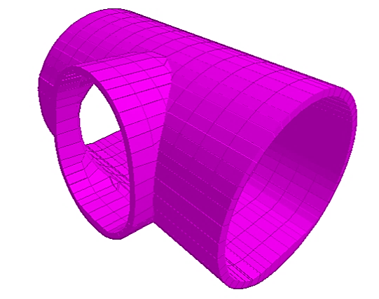
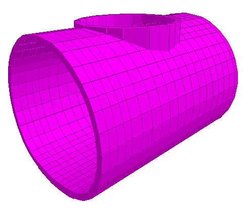
Figure 1 – Platform tunnel to cross passage Figure 2 – Shaft to tunnel 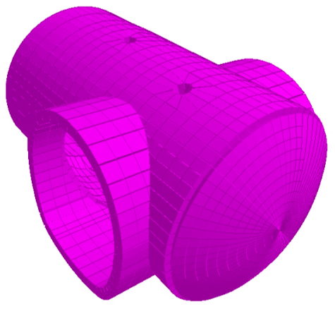
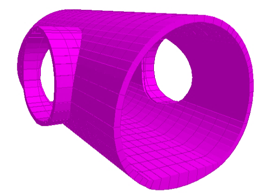
Figure 3 – Concourse tunnel to cross passages with headwall Figure 4 – Concourse tunnel to cross passages 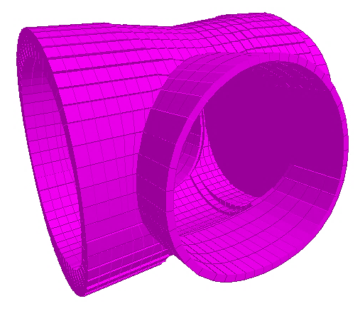
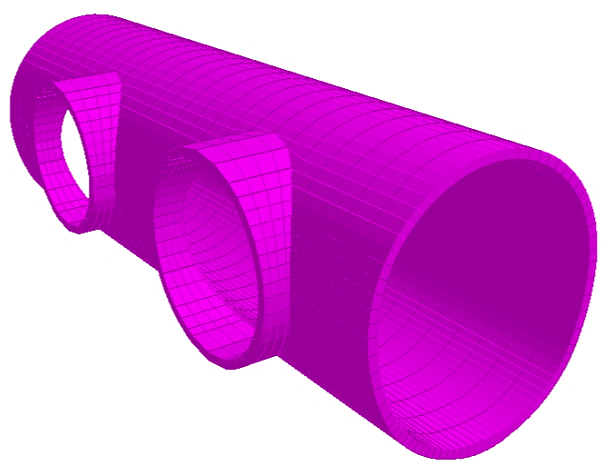
Figure 5 – Wraparounds Figure 6 – Twin Openings The design methodology of permanent complex structures like junctions comprises the following stages:
- 3D FEM modelling process:
- Meshing: Challenges of the geometrical assembling (meshing size) of complex structures.
- Soil – structure interaction element: Design of the boundary conditions of the 3D model.
- Material properties.
- Loading conditions: loads and load combinations as per Eurocode 0 [9] and Eurocode 1 [10].
- Assessment of outputs of the 3D model.
- Structural design as per RILEM [6] and Eurocode 2 [4].
- Detailing of rebar as per Eurocode 2 [4].
All these parts of the design methodology are thoroughly explained in this paper to understand the benefits of this approach in the design of complex permanent structures and show a method to assess the structural behaviour of these junctions in their various configurations.
Furthermore, assessment of the most critical junctions in accordance with the ground properties, levels and geometry of tunnels, and boundary conditions of junctions are also presented in the paper.
2 Description of junctions
Junctions are structural elements in tunnels that are formed by the connection between a main tunnel with a larger dimension called “parent tunnel” and a second tunnel with smaller diameter called “child tunnel”. The main junctions are set up between platform tunnels and cross passages, and between concourse tunnels and cross passages. There are also other junctions such as concourse tunnels and shafts in which openings can be placed either at the crown or invert (such as for sumps and ventilation adits).
The secondary lining in junctions is defined by contraction joints that are located between 4 to 8 meters from the opening centre line in parent tunnels, and between 1 to 2 meters in child tunnels. Junctions can be either designed in sprayed concrete and cast in situ concrete with or without Steel Fibre Reinforced Concrete (SFRC). Since the primary lining is not a waterproofing element, contraction joints of the secondary lining might become potential zones of leakage thus, to guarantee the watertight conditions, all contraction joints are designed with water-barriers and re-injectable grout tubes along the joint in radial and axial direction.
2.1 Selection criteria of representative junctions
As there are several junctions in each Crossrail Station and most of them present similar geometric characteristics, a selection of the most representative junctions are presented. This exercise has been done based on the following significant factors (i.e. the deepest one, the one with the biggest aspect ratio, the one with the higher pore water pressure, etc):
- Ground conditions
- Depth of Junctions
- Geometry
- Boundary conditions
2.2 Geometry of representative junctions
Geometrical properties of tunnels of different types of junctions designed with this methodology (described in this paper on sections 3 to 5) are detailed in table 1:
Table 1 – Geometry of Junctions
Type of junction Parent tunnel diameter at tunnel axis level
(m)
Child tunnel diameter at tunnel axis level
(m)
Aspect ratio Parent tunnel secondary lining thickness
(mm)
Child tunnel secondary lining thickness
(mm)
Single junction – STW1 – VA1 (FAR) 9.60 6.85 0.7 350 300 Double junctions (Type 2) – AP6a to AP10a&b (LIS) 5.35 4.50 0.84 300 275 Wraparounds (Type 3) – PTE to CP6
(LIS)
9.95 7.50 0.75 250 250 CH7 to shaft
(LIS)
6.0 4.05 0.7 250 250 LCE to VD4 & VD5 (Type 4) (LIS) 8.95 7.0 (VD5) & 6.0 (VD4) 0.78 (VD5) – 0.7 (VD4) 300 300 (VD5) & 250 (VD4) 3 Finite Element Modelling (FEM) – STAAD Software
STAAD.Pro v8i is a structural analysis and design program that is based on the Finite Element Method. It can efficiently generate finite element geometry for complex structures with openings such as junctions in tunnels. The modelling process and analysis carried out using STAAD.Pro provided the results of the analyses in terms of the predicted axial and shear forces, bending moment and deformation of the secondary lining under long-term conditions.
3.1 Inputs in STAAD.Pro V8i
Since the modelling process in STAAD is a complex task, the best way of understanding this process is thoroughly detailing the structural modelling process that has been utilised by C121 for the Crossrail Project.
3.1.1 Geometry
The geometric construction of 3D models for tunnel junctions is the most time-consuming part of this methodology. For Finite Element (FE) models the Designer selects the appropriate mesh sizes to achieve the following:
- Accurate geometrical representation of the behaviour of the selected junction.
- Finer mesh sizing at points of isolated loads to achieve accurate output.
- Coarser mesh at zones where construction is unlikely to change the stress conditions prior to the construction of the junction.
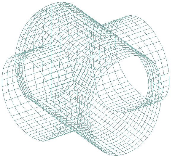
- The required level of numerical accuracy i.e. the fineness of the mesh (see figure 7).
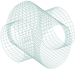
Figure 7 – 3D model mesh for a double junction
3.1.2 Material
Concrete properties to model the secondary lining in junctions have been used in accordance with both specifications KT20 SCL[1] and KF10[2] Cast in situ concrete and paragraph 4.6.4 of the SCL Numerical Modelling Guidelines, Rev 9.0[3]:
- Concrete Grade: C32/40 at 90 days
- Density: 2500 kg/m³
- Poisson ratio: 0.2
- Young’s modulus: 17 GPa
- Coefficient of thermal expansion: alpha: 10-5 K-1
3.1.3 Boundary conditions
The interaction between soil and the structure is established through springs-beams attached to every node of the plates that form the 3D model. The radial beam-springs act in compression only as compressive stresses are transferred between the tunnel and the surrounding mass. The stiffness Ki [kN/m/m] of the radial spring at node “i” is determined by using the following equation:

(1)
where ‘Esi’ (kN/m²) is the modulus of elasticity of the soil surrounding the tunnel at that certain node, ‘Ri’ (m) is the radius of the lining at the given node, while Si (m) is the surface associated with the node of the element in circumferential direction along which the spring is operating.

Figure 8 – Spring beams model
Ending supports have to be implemented in the model. These represent the contraction joints by means of stiff springs acting in compression only along the tunnel axis. This support condition is applied at both endings of the parent tunnel and the ending of the child tunnel in their respective directions.
Figure 9 – Spring supports in PTW to CP3a single Junction, Liverpool Street
3.1.4 Loading and load combinations as per BS EN 1990 and BS EN 1991
3.1.4.1 Self-weight
Self-weight is applied on the whole structure except for the spring beams representing soil as these are not structural elements of the model.
3.1.4.2 Earth pressure
The earth pressure acting on the secondary lining is determined in accordance with the results of FLAC analysis for the long term (120 years). The radial contact pressure on the interface between primary and secondary lining consists of both ‘active’ and ‘passive’ load (bedding reaction from deformation of the tunnel lining).
The principle is illustrated in Figure 10 by the total (i.e., active + passive) ground pressure (hatched line) and its active load (solid bold line). In a spring-beam model, only the ‘active’ part of the ground pressure load should be applied onto the secondary lining. The ‘passive’ part of the ground load is provided automatically by the springs.
This structural model in STAAD withstands the shared ground load between primary & secondary linings and the full pore water pressure in long term conditions (up 120 years), the temperature loads (winter and summer), drying shrinkage and finally a surcharge of 75 kPa applied on the surface.
Figure 10 – Total and ‘active’ ground load
This model also considers a sharing ground load effect between the primary and secondary lining working as a composite support.
The ground load is applied perpendicular to the surface above axis level and linearly decreases from crown to the invert where the pressure is nil. The following example, junction STW1-VA1 at Farringdon, illustrates the ground load distribution along the lining (see Figure 11).
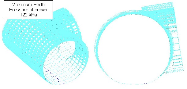
Figure 11 – Earth pressure profile
3.1.4.3 Pore Water pressures (PWP) ULS and SLS
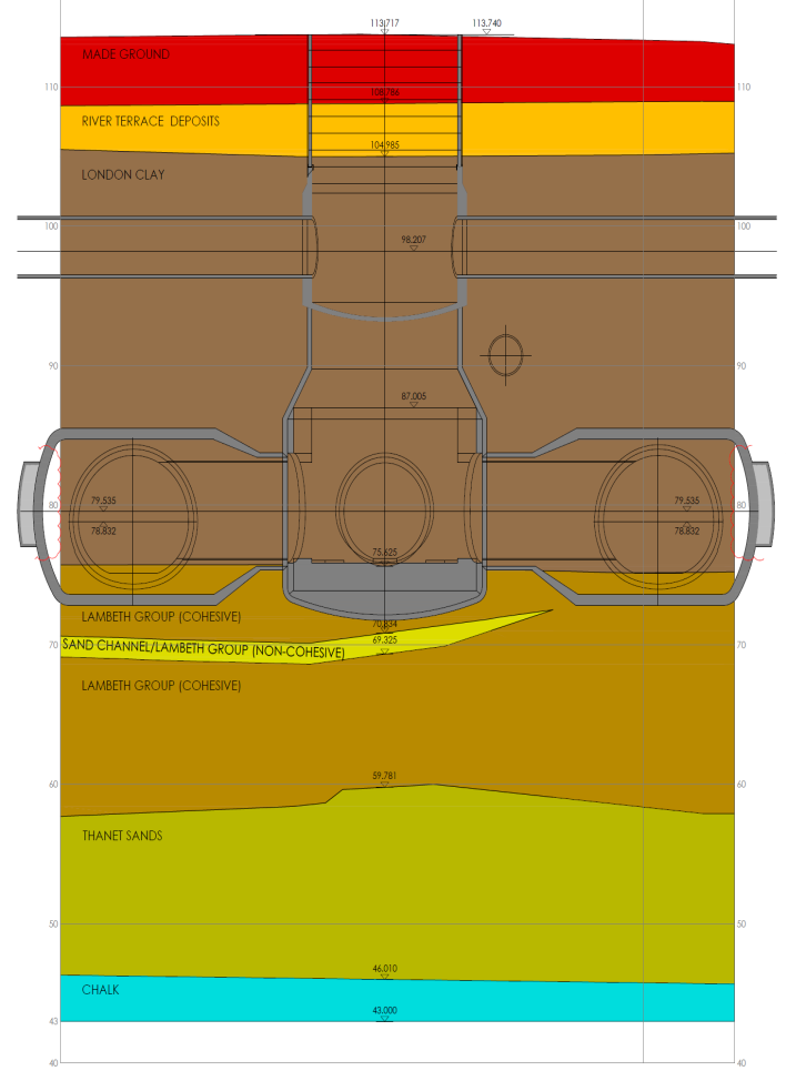
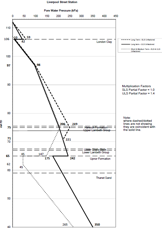
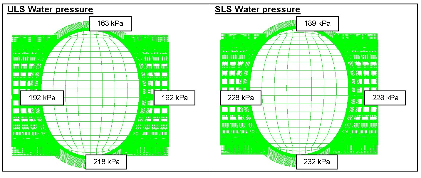
The ULS (ultimate limit state) and SLS (service limit state) water pressure is depth-dependant and is taken from the water pressure profile for each station. To illustrate this load a template in junction CP5/6 Wraparound at Liverpool Street is shown in Figure 12 and Figure 13.
Figure 12 – Pore water pressure variation with depth
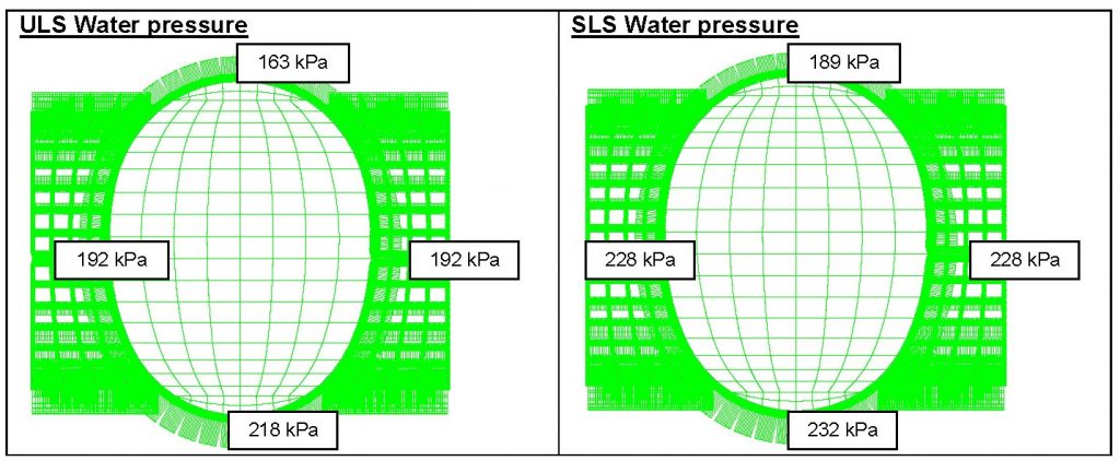
Figure 13 – Pore water pressures at CP5/6 wraparound
3.1.4.4 Drying shrinkage
Shrinkage is determined according to Eurocode 2 where strains are a combination of drying and autogenous shrinkages.
Shrinkage depends on concrete parameters and lining thickness and it is simulated as a change in temperature. The following shrinkage values (considered as temperature increments ΔT) have been applied as follows depending on the different thicknesses of secondary lining elements:
Table 2 – Shrinkage values
Thickness (mm) ε (10-4) ΔT ( C) 300 2.90 24.2 500 2.80 23.1 800 2.60 21.3 1200 2.30 19.0 3.1.4.5 Temperature loads
In addition to the concrete temperature at the time of installation, the following temperatures at tunnel level have been defined for the analysis of the secondary lining.
Table 3 – Absolute design temperatures
Face Summer temperature (° C) Winter temperature (° C) Extrados (far face) 25 10 Intrados (near face) 30 15 3.1.4.6 Load combinations
The load combinations are defined as per BS EN 1990:2002 (Eurocode 0) Basis of structural design.
The ULS and SLS load combinations and applied factors as described in Numerical Modelling Guidelines[3] are presented in this section (see Table 4, Table 5 and Table 6).
Table 4 – Loads and related load factors used in the model
ID Load type Description I Self-weight γG = 1.40 (ULS) / γG = 1.00 (SLS) II Ground (earth) pressure γG = 1.40 (ULS) / γG = 1.00 (SLS) (vertical and horizontal ground loading including surcharges) III Water pressure ULS γG = 1.40 IV Water pressure SLS γG = 1.00 V Traction Load γG = 1.40 (not included in the analysis) VI Shrinkage strain γG = 1.40 (ULS) / γG = 1.00 (SLS)
Combination factor ψ0 = 0.6
VII Summer temperature γQ = 1.50 (ULS) / γQ = 1.00 (SLS)
Combination factor ψ0 = 0.6
VIII Winter temperature γQ = 1.50 (ULS) / γQ = 1.00 (SLS)
Combination factor ψ0 = 0.6
NB: γG is the partial factor for permanent actions, γQ is the partial factor for variable actions,
Table 5 – ULS combinations and applied factors (partial and combination factors)
Load I II III IV V VI VII VIII Combination 1 1.4 – – – – 1.40 x 0.6 – 1.50 x 0.6 2 1.4 – – – – 1.40 x 0.6 1.50 x 0.6 – 3 1.4 – 1.4 – – 1.40 x 0.6 – 1.50 x 0.6 4 1.4 – 1.4 – – 1.40 x 0.6 1.50 x 0.6 – 5 1.4 1.4 – – – 1.40 x 0.6 – 1.50 x 0.6 6 1.4 1.4 – – – 1.40 x 0.6 1.50 x 0.6 – 7 1.4 1.4 1.4 – – 1.40 x 0.6 – 1.50 x 0.6 8 1.4 1.4 1.4 – – 1.40 x 0.6 1.50 x 0.6 – Table 6 – SLS combinations and applied factors (partial and combination factors)
Load I II III IV V VI VII VIII Combination 1 1.00 – – – – 1.00 x 0.6 – 1.00 x 0.6 2 1.00 – – – – 1.00 x 0.6 1.00 x 0.6 – 3 1.00 – – 1.00 – 1.00 x 0.6 – 1.00 x 0.6 4 1.00 – – 1.00 – 1.00 x 0.6 1.00 x 0.6 – 5 1.00 1.00 – – – 1.00 x 0.6 – 1.00 x 0.6 6 1.00 1.00 – – – 1.00 x 0.6 1.00 x 0.6 – 7 1.00 1.00 – 1.00 – 1.00 x 0.6 – 1.00 x 0.6 8 1.00 1.00 – 1.00 – 1.00 x 0.6 1.00 x 0.6 – 4 Outputs & Results
Resultant features of the analysis in STAAD are based on the matrix displacement method. In the matrix analysis of structures by the displacement method, the structure is first idealized into an assembly of discrete structural components (plates) as the loads are applied in the form of distributed loads on the element surfaces or as concentrated loads at the joints (as described above).
4.1 Output Member Stresses & internal Forces
STAAD calculates member stresses specified at intermediate sections as well as at the start and end joints. These stresses include:
- Axial stress (Si)
- Bending-y stress (Mi)
- Shear stresses (SQi) and
- Combined stress (Top Combined SX & SY and Bottom combines SX & SY) which is the sum of axial-i and bending-i stresses.
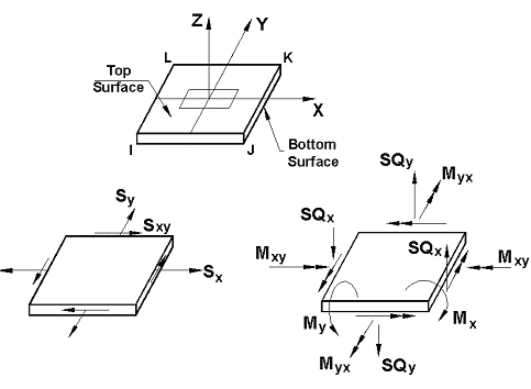
Figure 14 – Stresses and Moments on Plate Elements
4.2 Force Envelopes
STAAD also generates force envelopes of the member forces FX (axial force), FY (Shear-y), and MZ (bending moment) for any number of intermediate sections (see Figure 14).
The following is the sign convention for the maximum and minimum values:
- FX – A positive value is compression, and negative tension.
- FY – A positive value is shear in the positive y-direction, and negative in the negative y-direction.
- FZ – Same as above, except in local z-direction.
- MZ – A positive moment will mean a moment causing tension at the top of the member. Conversely, a negative moment will cause tension at the bottom of the member. The top of a member is defined as the side towards positive local y-axis.
- MY – Same as above, except about local z axis.
4.3 Description of a practical case
Access Passage AP6a is a pedestrian tunnel within the Northern Line Link between the Crossrail Liverpool Street Station and the London Underground Moorgate Station.
AP6a (parent tunnel) is an unusual tunnel since it has a double junction to two other tunnels (child tunnels) AP10a and AP10b (each of them with different dimensions and shapes), a headwall, a sump and two service chutes on its crown as per Figure 15.

Figure 15 – Plate model and thickness model representation
The secondary lining thickness and diameter for each tunnel section is listed below as shown in Table 7:
Table 7 – Secondary lining properties
Tunnel Diameter (m) Concrete Thickness (mm) AP10a Child Tunnel 4.00 SFRC – Arch 300 Cast-In-Situ Invert Variable
250 to 460
AP10b Child Tunnel 4.50 SFRC – Arch 275 Cast-In-Situ Invert 225 AP6a 5.35 SFRC – Arch 300 Cast-In-Situ Invert 350 Headwall 5.35 SFRC – Arch 250 Sump (AP6a) 1 x 1 Cast-In-Situ Invert 250 Once the model has been completed in terms of inputs as described in Section 3, it is run and post-processed. Once the model is run, the post-process stage follows where certain or all load combinations can be selected as STAAD has calculated deformations, stresses and forces for each one of them.
4.3.1 Deformed shape
The first parameter presented in STAAD is the deformed shape which is the calculation of the displacements at every single node of the model and available for each individual load case and load combinations in ULS and SLS as shown in Figure 16, Figure 17 and Figure 18.
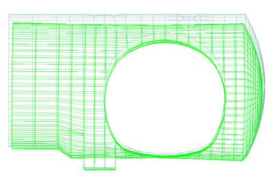
Figure 16 – Elevation view – Deformed shape under load case SLS 07
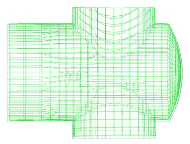
Figure 17 – Top view – Deformed shape under load case SLS 07

Figure 18 – Cross-section – Deformed shape under load case SLS 07
The deformed shapes are used to determine whether the crown or invert of the section is stressed.
4.3.2 Internal Forces: Axial Forces, bending Moments and shear forces
STAAD presents the internal forces: axial forces and bending moments along two local axis: X and Y. When analysing tunnels it is recommended that the local axis x follows the “longitudinal” direction of the tunnel while local axis y follows the “hoop” direction of the tunnel. The following Figure 19 shows the typical orientation of the local axis in tunnels:
Figure 19 – Local axis direction to interpret forces and stresses
STAAD presents the axial stresses, bending moments and shear stresses in both directions X (longitudinal) & Y (hoop). The axial and shear forces can be calculated by multiplying these values by the thickness of the element.
2.3.2.1 Combined stresses
The combined normal stresses are calculated as:
Along local X (Figure 20):
(2)
Along local Y (Figure 21):

(3)
Where:
(4)
t is the thickness of the element.
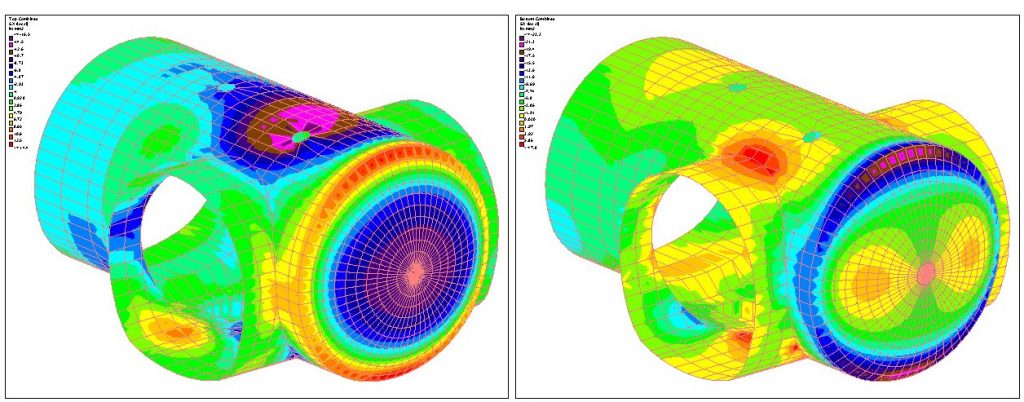
Figure 20 – Top combined stresses SX in X (longitudinal) direction in crown and invert sides
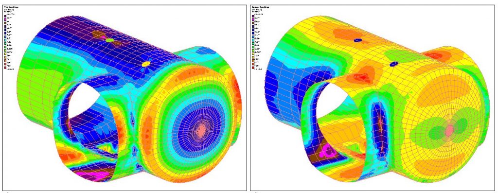
Figure 21 – Top combined stresses SY in Y (hoop) direction in crown and invert sides
Once the combined stresses have been obtained for every load case and every load combinations and having determined which of them is the critical case then the structural analysis follows and the calculation of additional (aside of SFRC) reinforcement if required. These stages will be described in the following sections.
5 Structural Design and Reinforced Concrete RC Detailing
Steel quantity calculation is done according to Eurocode 2.0
The process of detailing is based on the following standards:
- Eurocode 2. BS EN 1992-1-1 [4].
- Eurocode 2 BS EN 1992-1- 2 [5].
- RILEM TC 162-TDF [6].
- CIRIA C660 [7].
- BS 8666:2005 [8].
The process starts assessing two main results of the calculation:
- The need of rebar in different zones according to the Moment-Axial design capacity check.
- Zone under tensile stresses according to the stress contours obtained in the 3D model.
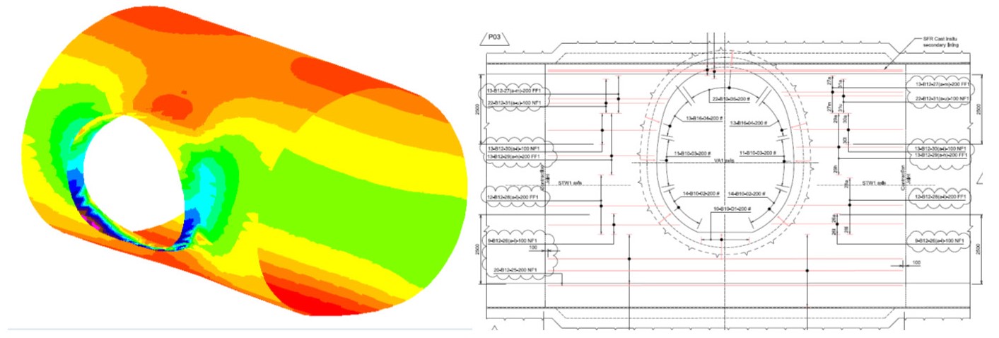
Therefore, if there is a need for reinforcement in some specific areas, these areas are limited to the plotted contours in the 3D model as is described below in Figure 22:
Figure 22 – Stresses contour on near face
Areas with tensile stresses bigger than approximately 3 N/mm2 (for a 300mm thickness lining) are the zones where reinforcement is needed. These contours are compared with the tensile strength of the SFRC which depends on the thickness in each case.
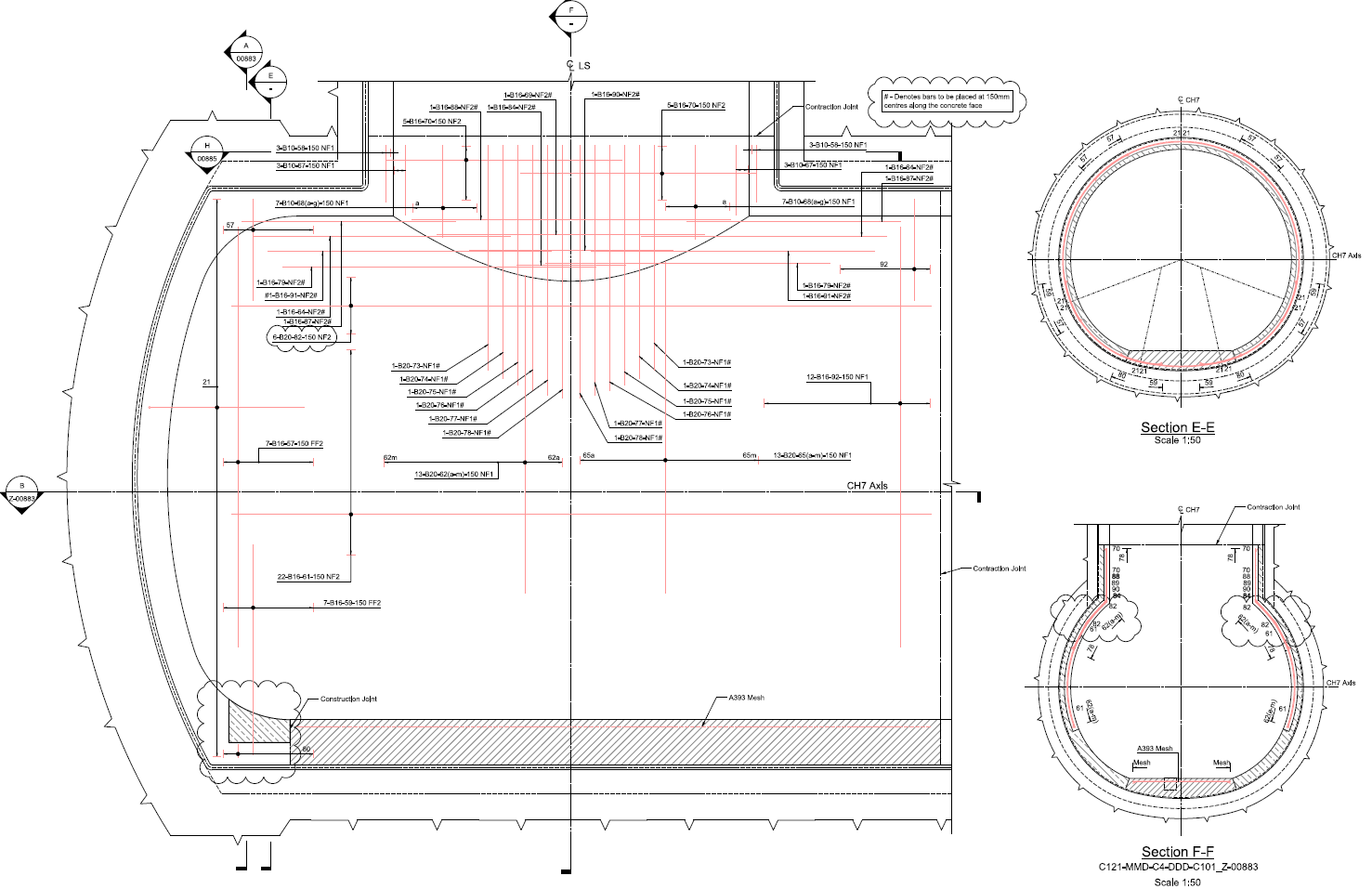
The rebar in these areas is designed for the minimum length of anchorage and lapping as per Eurocode 2. Scheduling, dimensioning, bending and cutting of steel are designed following the BS8666 requirements (see Figure 23).
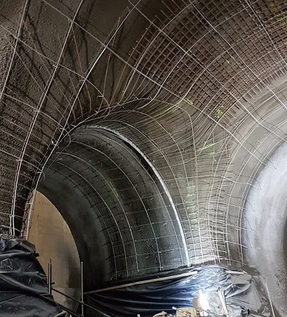
Figure 23 – Detailing of rebar. Near face at top heading connection
Aside from Eurocode 2 requirements in terms of detailing, the following rules have to be considered for sprayed lining (SCL) with reinforcement:
- No spraying of bars greater than 16 mm diameter at 150 mm centres as encapsulation problems are much more likely with larger diameter bars. This also applies to groups of bars than when considered together in terms of diameters and spacing build up to the same concentration of steel. This statement is exclusively for SCL (with steel fibres).
- No spraying is possible through areas that structurally require shear links.
- No spraying through two layers of reinforcement.
- In the interface between reinforced cast in situ concrete and reinforced sprayed concrete the overlapping of the reinforcement in the cast invert with the reinforcement in the sprayed concrete would require spraying through two layers of reinforcement. This is to be solved by installing the far face reinforcement and adding positional couplers to the near face so the spraying of only one layer of reinforcement at a time is undertaken.
- Concrete sprayed through reinforcement to be preferably no steel fibre in order to avoid encapsulation. Lining therefore could be sprayed in alternate layers of steel fibre reinforced concrete and non SFR concrete.
6 Summary of Outputs of representative junctions types
In this section the assessment of the most critical junctions selected based on ground properties, levels and geometry of tunnels and boundary conditions of junctions are described:
6.1 Assessment of the structural behaviour of representative tunnel junctions.
The assessment is set up considering the following aspects:
- Ground conditions, levels and ground water: the parameters of the ground define how the ground loads are acting on the secondary lining. For instance junctions in London Clay will be withstanding more pore water pressure than junctions located in the Lambeth Group due to different permeabilities and soil stiffness.
- Junction depth: the level of tunnel axis will determine the ground pressure that will be transferred to the secondary lining when this load is shared between both linings, primary and secondary, as is set up in the Numerical Modelling guideline [3]. Deeper junctions will be most critical since more ground pressure will be acting on the lining.
- Geometry: The following geometric factors are important:
- Number of child tunnels: single junctions, or double junctions where deflections and tensile stress are larger.
- The ratio between the diameter of the smaller (child) tunnel and larger (parent) tunnel has a considerable influence on the design and typically varies between 0.4 and 0.8. Tunnel junctions with larger aspect ratios have been selected since tensile stresses are larger on the crown zone of the connection on near faces.
- The location of the child tunnel opening with regards to the parent tunnel, i.e. this opening can be located at sides of the parent tunnel forming a typical junction or the openings can be located at crowns which is the case of shafts connection with cross passages.
- Thicknesses of linings are important when junctions are cast in situ in different pours and, thus, the Early Age Thermal Cracking (EATC) has to be considered in the design.
- Boundary conditions: It is important to evaluate the potential impact of a nearby structural element such as headwalls, sumps and shafts on junctions. Headwalls, for example, have an important impact with regards to the reinforcement design when located very close (less than 2m) to the openings of child tunnels.
These factors determine the structural behaviour of selected representative junctions in C121 SCL stations. This selection is summarised in the following table (matrix of junction assessment):
Table 8 – Matrix of junction assessment
Typology of junctions / Number of child tunnels Station Type of ground Tunnel axis level – depth Pore water pressure (PWP) Boundary conditions Junction selected / main selection factor Single junction FAR(Loading conditions – PWP pressure bigger at crown level) London clay – LC3 106 mATD – 20 m 110 KPa crown to 50 kPa invert. Contraction joints all ends STW1/VA1 (worst ground conditions) Shaft to tunnel LIV
(Only with this sort of junctions)
London Clay – LC3 79 mATD – 35 m 200 KPa crown to 240 kPa invert. Contraction joint / headwall LS – CH7 to Shaft (Worst condition in shear) Double junction -Type 1 WHI (deeper) London Clay – LC3 88 mATd – 24m
150 KPa crown to 120 kPa invert. Contraction joints and headwall CP1a to EPW1 (bigger aspect ratio) Double junction – headwall – Type 2 LIV – NLL London Clay – LC3 82 mATD – 32m 180 KPa crown to 220 kPa invert. Headwall in parent tunnel, in other ends, contraction joints AP6a to AP10a / AP10b (loading conditions – PWP) Wraparound (Double junction type 3) LIV (thicker lining) London Clay – LC3 79 mATD – 35m 190 KPa crown to 250 kPa invert. Headwall in child tunnel and contraction joints in other ends CP5 / CP6 to PTE/PTEW (thickness – EATC impact) * Geometric properties are described in table 1.
6.2 Outputs from representative tunnels junctions
6.2.1 Single junctions: Platform tunnels to cross passages. Farringdon Station STW1-VA1 junction.
Output: Near Face Stresses Hoop Direction

Figure 24. Single Junctions: Platform tunnels to cross passages
The model contours with tensile stresses higher than 3 N/mm2 are zones where the most critical tensile stresses are concentrated. These tensile stresses are bigger than the maximum tensile strength of the SFRC, thus additional reinforcement is needed on near faces. Furthermore, these contours define the limit length of reinforcement in terms of detailing to ensure the correct anchorage and lapping.
6.2.2 Single junctions: Access passage to shafts. Liverpool Station. LS to CH7.
Output: Shear stresses around the shaft connection
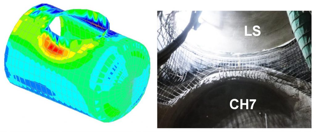
Figure 25. Single junctions: Access passage to Shafts
The shear stresses are localized on the main tunnel where the shaft lining is punching and is governing the design against shear.
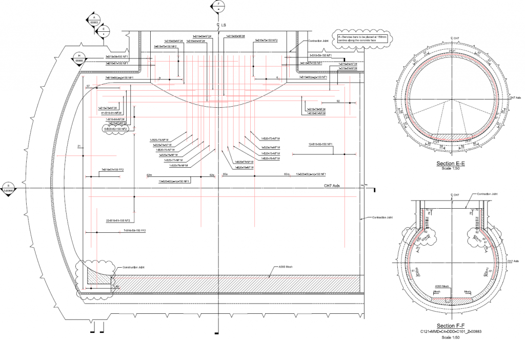
Figure 26. CH7 to Lift Shaft at Liverpool St Station
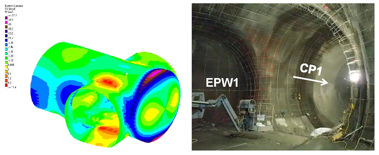
6.2.3 Double junctions type 1: concourse tunnels to cross passages. Whitechapel Station. CP1 to EPW1
Output: Near Face Stresses Longitudinal Direction

Figure 27. Double junctions type 1: concourse tunnels to cross passages
The tensile stresses are concentrated at crown and invert connection between parent and child tunnel, so reinforcement must be provided on those areas. The bigger the aspect ratio the higher additional reinforcement is required.
Figure 28. AP7 to CP1 and CP4 at Liverpool St Station
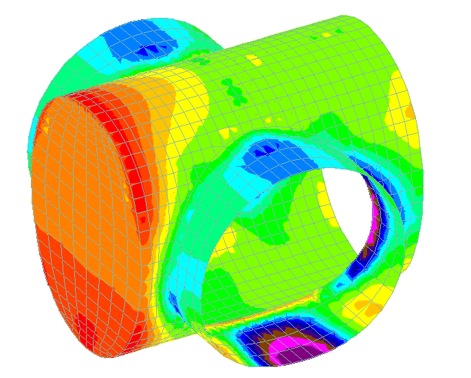
6.2.4 Double junctions type 2: concourse tunnels to cross passages and headwall. Whitechapel Station. CP1 to EPW1
Output: Near face stresses longitudinal direction
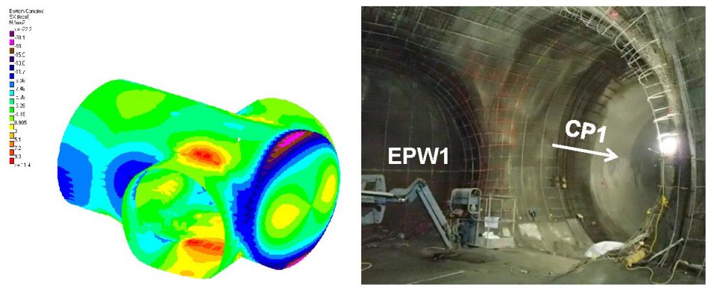
Figure 29. Double junctions type 2: concourse tunnels to cross passages and headwall
This case has stresses concentrated on near face in longitudinal direction. Furthermore, the headwall is withstanding heavy compression on near face what means tensile stresses will be concentrated radially and L bars will be needed to be installed on far face.
Figure 30. EPW1 to CP1 at Whitechapel Station
6.2.5 Double junctions type 3: wraparound where platform tunnels are the child tunnel. Liverpool Street Station. CP5/CP6 to PTE/PTW junction.
Output: Far face stresses in hoop direction
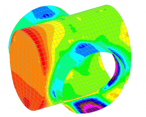
Figure 31. Double junctions type 3: wraparound tunnels
These contours show tensile stresses around the headwall in far face what means reinforcement in hoop direction on far face will be required and heavy compressions on inverts on bottom faces what is a usual resultant from the pore water pressure loading. Tensile stresses are encountered on top faces of the invert.
Figure 32. PTE to CP6 Wraparound at Liverpool St Station
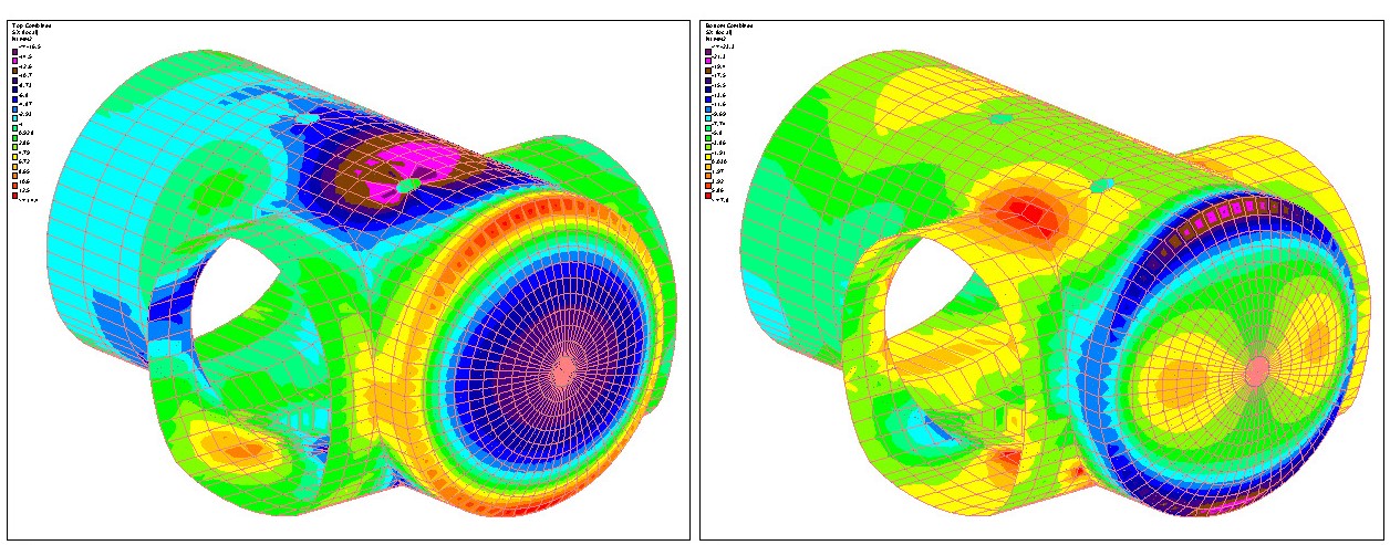
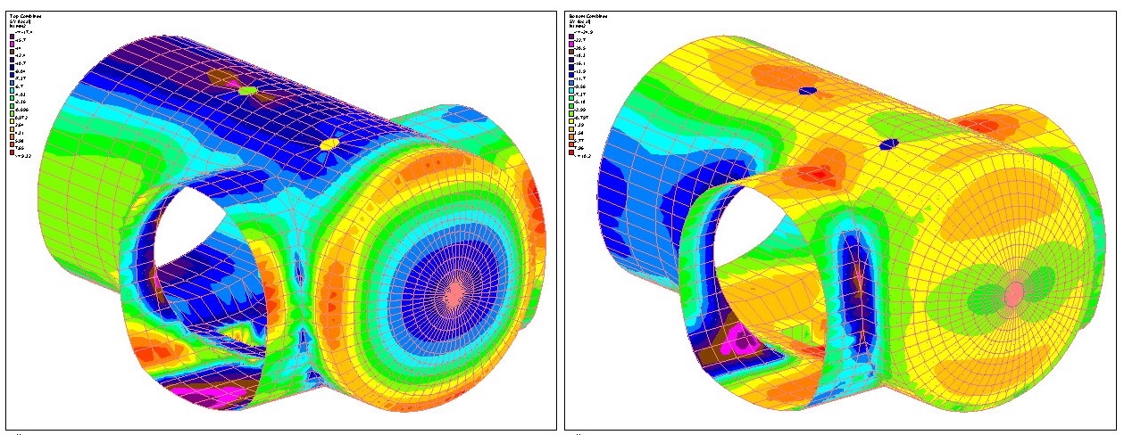
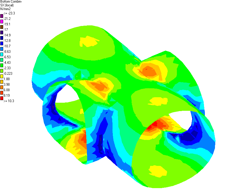
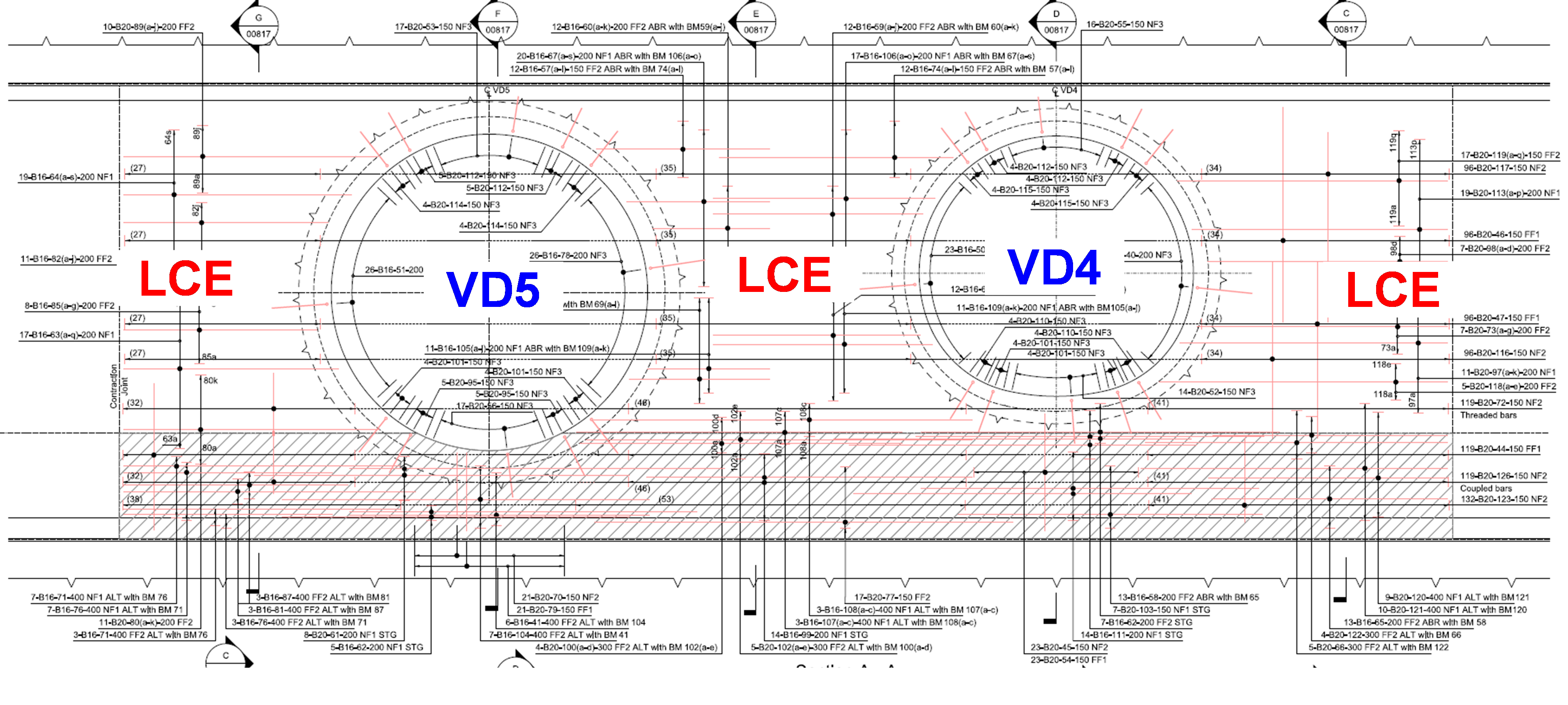
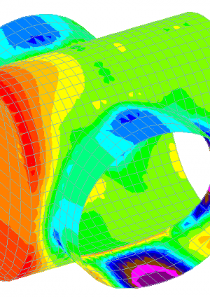
6.2.6 Double junctions type 4 (Twin openings): Launch Chamber to ventilation ducts. Liverpool Station. LCE to VD4 and VD5 junctions.
Outputs: Stresses in hoop direction and far face stresses in longitudinal direction.
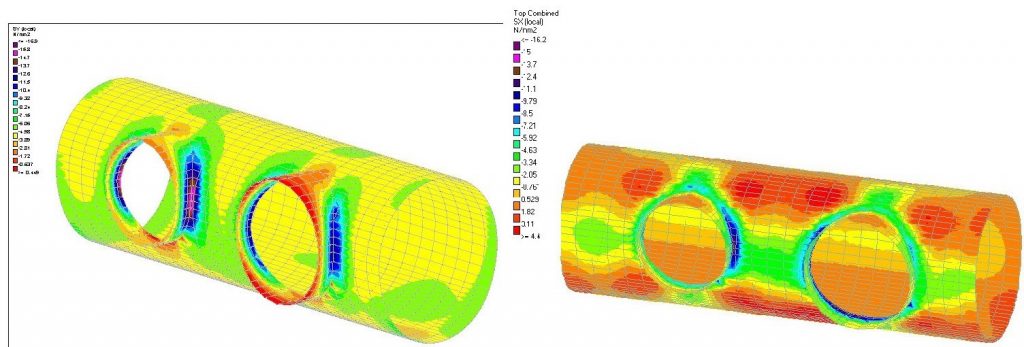
Figure 33. Double junctions type 4: Twin openings
The stresses in hoop show strong compressions between both child tunnels that have been checked against the maximum compression strength of the SFRC. This concentration of compression stresses is usual in junctions with two very close child tunnels. Furthermore, there is a concentration of tensile stresses on the far face in longitudinal direction between both child tunnels (above and below the tunnel axis). Longitudinal reinforcement is needed to be extended between both child tunnels, and between each child tunnel and joints located at the ends on the model.

Figure 34. LCE to VD4 and VD5 at Liverpool St Station
7 Conclusions
This paper has presented a method of designing secondary linings considering the contribution primary lining in sprayed concrete structures with complex geometries. The method was found to have the following advantages:
- The system of calibration between 2D models for soil-structure interaction (FLAC in this case) and more typical structural design software (STAAD) avoided the need for extensive use of 3D geotechnical modelling software, which is typically very time consuming.
- The standardization of the design method allowed many different geometry schemes to be undertaken without repeating all modelling from the beginning. With a project as geometrically complex as Crossrail, with many different cross-passage, ventilation adits and access passage geometries, this allowed a great number of different junction types to be analysed relatively quickly.
- The method allows the benefits of the two programmes used to be utilised to their full. In the case of FLAC, the design of the primary lining, where SLS states are not of interest, the soil-structure interaction is key. For the secondary lining, STAAD is able to add load cases such as temperature, shrinkage, internal and accidental loads. The SLS load cases can be considered in more detail as they apply to the secondary lining.
- The method allows specific areas of junctions to be identified to ensure that heavy reinforcement, if needed at all, is limited to stress and bending moment concentrations. This minimises working at height to fix reinforcement and is extremely important for sprayed linings as the reduction of reinforcement improves workmanship.
- The identification of areas with concentration of stresses is key to whether decide the real need for additional reinforcement or further analysis. Usually, further analysis is the preferred and is usually done through:
- Allow for plastic hinges to develop and check rotation in both primary and secondary lining. This allowed reinforcement to be avoided in some areas.
- Allow stress concentrations considered to be unrealistic to be smoothed out over immediately adjacent parts of the structure, e.g. in tight corners around the immediate perimeter of the junction openings.
In using this method, patterns can be seen in the behaviour of junctions:
- The near and far face bending patterns are typically very similar (although with differing magnitudes), as can be seen by the various displacement plots shown throughout this paper. An exception is egg-shaped parent tunnels, which can cause the moments immediately around the child tunnel perimeter to change tension face.
- It would likely be possible to define a standard spring stiffness for use in secondary lining models per project or per set of similar ground conditions and depths, without significant loss of accuracy.
- Junctions where the child tunnel approaches on a slope typically require more reinforcement. Along with tunnels approaching at an oblique angle in plan, these are also significantly more difficult to detail. Such geometry would be best avoided from a pure tunnelling perspective. However, many other factors rightly govern the geometry and the method presented here has proven able to cope with such cases. Such flexibility is invaluable for new stations in dense urban areas.
- In general, the reinforcement of the cast-in situ invert slabs was unaffected by the presence of the opening. In this case, the simpler 2D analysis used for areas remote from the junction usually governed for the invert reinforcement. Exceptions are openings directly in the invert (e.g. sumps).
- Double facing junctions, e.g. those from concourse to cross-passages presented here, cannot generally be assumed to behave as mirrored single junctions, especially as the aspect ratio child/parent grows.
8 References
[1] KT20: C121 – SCL Specification Sprayed Concrete Linings
[2] KF10: C122-M&W Specification – In-situ Concrete
[3] SCL Numerical Modelling Guidelines (C121 Document)
[4] Eurocode 2. BS EN 1992-1-1 Design of concrete structures. Part 1.1: General rules.
[5] Eurocode 2 BS EN 1992-1- 2 Design of concrete structures. Part 1.2: Structural fire design.
[6] RILEM TC 162-TDF: ‘Test and design methods for steel fibre reinforced concrete’.
[7] CIRIA C660: Early-age thermal crack control in concrete.
[8] BS 8666:2005: Scheduling, dimensioning, bending and cutting of steel reinforcement for concrete — Specification.
[9] BS EN 1990 Eurocode 0
[10] BS EN 1991 Eurocode 1
-
Authors

Eleanor Sillerico Mayta MSc - Mott MacDonald
C121 Tunnel Design Lead

Jose Suarez Diaz MSc CEng MICE - Mott MacDonald
C121 Design Manager