Duty & Stand-by Arrangements for VRF and DX Cooling Systems
Document
type: Technical Paper
Author:
Matthew David BSc CEng MIMechE MCIBSE, Bill Wilkinson, ICE Publishing
Publication
Date: 30/09/2017
-
Read the full document
1 Introduction
Electrical equipment can generate heat. Certain rooms containing electrical equipment must be cooled to remove heat and ensure reliability of the contained equipment.
Cooling systems are used to cool the rooms. Cooling of these rooms can be critical and a backup source of cooling (stand-by) may be required. Depending on the location, Direct Expansion (DX) or Variable Refrigerant Flow (VRF) cooling systems are used in different arrangements to provide duty and stand-by cooling to all the required rooms.
There are two different running strategies that can be used for these systems: hot stand-by and cold stand-by. This paper explains the benefits of cold stand-by over hot stand-by, in terms of wear and efficiency, and why the cold stand-by running strategy is preferred by Crossrail.
2 Terms & Definitions
Terms and definitions are as Table 1.
Table 1: Terms and Definitions Used
Term
Definition
VRF
Variable Refrigerant Flow. The condenser serves multiple FCU’s. The refrigerant flow can be varied to achieve different rates of cooling. DX
Direct Expansion. The condenser usually serves one FCU and controls temperature through switching on and off. FCU
Fan-Coil Unit Duty
The prime source of cooling. The units are sized to provide 100% of cooling duty and are enabled as the prime source of cooling. Stand-by
Backup source of cooling. The units are sized to provide 100% of the cooling duty and are enabled if there is a failure or after rotation as a backup source of cooling. n+1
‘n’ duty units with 1 stand-by unit. e.g. 2 duty, 1 stand-by. n+n
‘n’ duty units with ‘n’ stand-by units. e.g. 2 duty, 2 stand-by. 3 Principles
3.1 Hot Stand-by
The hot stand-by running strategy consists of all units in a system running with shared load. One system will ramp up if the other system is taken out of service for maintenance or due to failure. This running strategy is also known as duty assist.
3.2 Cold Stand-by
The cold stand-by running strategy consists of one or more systems running, with at least one stand-by system that is not running. The change over of duty cooling units is rotated on a timed schedule, e.g. 1 week on/1 week off. When maintenance is required, the cooling system to be maintained will be taken out of service and duty will automatically switch over to the other system.
4 Discussion
4.1 Oversizing of Cooling Systems
A hot stand-by running strategy is typically unsuitable across the Crossrail project. The key reason is that the cooling systems are sized for a worst case heat gain to the room, which is unlikely to ever be realised. During design, cooling units were sized based on equipment loads provided by the Systemwide contracts, often the worst case scenario heat dissipation. However, in reality these values may not be reached and if they are it would be a rare occurrence. The units are manufactured with a range of sizes. The next largest size above the design duty is selected for the application. Sharing cooling load between multiple cooling systems (hot stand-by), may result in the cooling units operating at very low duties, below the recommended operating threshold of the product.
4.2 DX Arrangement
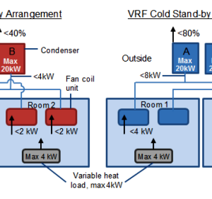
Figure 1 is an example to demonstrate the difference between two DX arrangements for a room, one running on hot stand-by and the other on cold stand-by.
With a hot stand-by arrangement the cooling systems are sized to provide at least 100% of the required load. With the hot stand-by example in Figure 1, the two cooling systems share the cooling load. As a result the condensers operate lower than their design threshold. As previously mentioned, operating loads <20% can significantly impact the efficiency of the condensers. The heat source will not constantly output a maximum of 4 kW, therefore the condensers will be operating at loads <2 kW – which is lower than 20% of the operating threshold.
With the cold stand-by example in Figure 1, one cooling system cools the room, this results in a condenser unit that takes on the full cooling load from the room (4 kW). As a result the condensers are more likely to be operating above their recommended operating capacity of 20%.
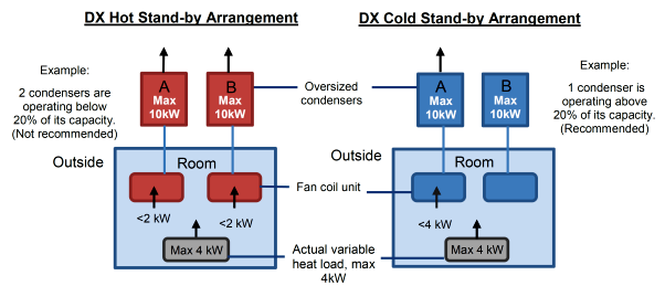
Figure 1 – Example schematic of hot and cold stand-by arrangements on DX systems
4.3 VRF Setup
Figure 2 shows two VRF systems, one running hot stand-by and the other is cold stand-by. This example demonstrates how a VRF system can be set-up with a more efficient cold stand-by arrangement. The hot stand-by set up is more likely to operate below the recommended load. The cold stand-by arrangement demonstrates how the full cooling duty can be fulfilled with half of the cooling units, thus increasing the load on the condenser unit to a more suitable level.
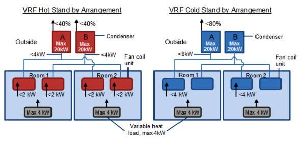
Figure 2 – Example schematic of hot and cold stand-by arrangements on VRF systems
4.4 Comparison of Running Strategies
Table 2 compares hot stand-by and cold stand-by running strategies. It displays the key benefits that cold stand-by holds.
Table 2. A comparison of hot stand-by and cold stand-by. The greyed out cells highlight advantages.
No Hot Stand-by
Cold stand-by
1 Faster wear as two systems run at one instance. Slower wear because only one system runs at one instance. 2 Inefficient due to the cooling load being shared between the systems. The condensers could run at less than the recommended minimum operating duty for much of the time. This will lead to the system switching on and off repeatedly (cycling). More stress on components due to frequent starts and stops. More efficient because the two systems do not run at the same time. Therefore the system is less likely to drop below its recommended minimum operating duty. The stand-by FCU internal fan does not run, resulting in less use of energy and the air filter. Less stress on components dues to less frequent starts and stops. 3 Less complex, this protocol is automatic on typical VRF systems. Running cold standby is not possible with all VRF set ups, such as interleaving pipework. e.g. 3 rooms served by 3 VRF systems, 3 condensers, and 2 FCUs in each room. 5 Conclusions
- Equipment loads provided by the Systemwide contracts are often for the worst case scenario heat dissipation. As a result many cooling systems are sized for duties rarely to be realised. If the load is shared between cooling systems in a hot stand-by arrangement, the condensers are likely to run at rates below recommended operating duty. This is inefficient.
- The cold stand-by running strategy is the preferred running strategy for DX and VRF air conditioning systems.
- Cold stand-by generates less stress on components due to greater run times and less cycling through starts and stops.
- Rotation protocol should be controlled at BMS level, or using a similar management system. This ensures that the cooling system activity can be remotely monitored.
- It may not be suitable to run a cold stand-by strategy on VRF systems that are ‘interleaved’. In these situations a hot stand-by running strategy may be more appropriate.
-
Authors

Matthew David BSc CEng MIMechE MCIBSE - Crossrail Ltd
Matthew David is a mechanical engineer with the Chief Engineers Group. He is responsible for the assurance of the design, installation, commissioning and handover of the mechanical systems for the stations, shafts and portals. He has been with Crossrail since March 2013. He has spent the previous 31 years designing buildings, of many types, around the world.

Bill Wilkinson - Crossrail Ltd
Bill is a mechanical engineer in Crossrail
