Earthing Design and Installation for the Elizabeth Line
Document
type: Technical Paper
Author:
Malcolm Anderson BEng(Hons) CEng MIET
Publication
Date: 02/12/2021
-
Read the full document
Introduction
The earthing system for a new railway is key and needs be considered at the inception stage of the project as it is fundamental to the location of critical systems such as traction substations, grid supply points etc. This early consideration is vital especially where the new railway will be located predominantly below ground and access to surface uncontaminated land is limited. The only opportunities for earthing the central section of the Elizabeth Line were at stations, shafts and portals (SSPs) due to the railway being located in the dense urban environment of central London and restrictions imposed by the limits of deviation set out in the Crossrail Act.
Modern bored tunnel metro systems are typically lined with pre-cast segmented concrete rings that do not provide a connection to the Earth within the tunnel. This is a potential benefit for a DC railway as it helps minimise stray currents but is a significant issue for an AC electrified railway where there is a requirement to connect to earth as often as possible for safety reasons.
Where railways are constructed in cities, there will be significant interactions with other railways, utilities (whether surface or buried) and infrastructure. These connections offer parallel paths for AC traction return current from the railway back to the traction feeder station, traction return currents through inadvertent paths can cause nuisance to other third party infrastructure, in particular communication systems and signalling equipment on other railways.
This paper examines the provision of the Elizabeth Line earthing systems from inception design through to delivery. Three principle topics are detailed, in turn:
- Main Earthing Design and Primary Construction
- Earth Zoning
- Stray Current
each principle topic section of this paper covers design, key issues and lessons learned which would also apply to similar 25kV AC auto transformer electrified railway built in a city with similar ground conditions; the paper concludes with overall future recommendations.
Main Earthing Design and Primary Construction
Earthing Outline Design
At the outline design stage, it was a requirement that the Elizabeth Line would be electrified at 25kV AC. In the design of a new traction system, the traction return and earthing system has to provide a low impedance path that is sufficient to clear faults within the short time voltage limit as described in BS EN 50122[1]. Another key consideration in the design of the electrification system is the rise of earth potential during faults.
The key to management of the rise of earth potential is to earth the traction return system down as regularly as possible. As part of the design process, the traction system was modelled to establish the fault clearance times and rise of earth potential experienced in various configurations; the modelling made assumptions as to the number and size of traction return conductors and other longitudinal metallic infrastructure.
In the central section of the Elizabeth Line the only locations where there was direct access to the earth was at the SSPs. This typically allowed the traction return system and the routeway systems to be earthed down typically every 2km to 3km.
The modelling confirmed that that the traction touch potential and the disconnection times would be met if the earth mats at traction feeder stations achieved 0.5 Ohm and the station, shafts and portal earth mats achieved 1 Ohm. The earth mats at the SSP’s were also to be used for earthing the non-traction HV and the LV systems.
Soil Resistivity and Geology
The Elizabeth Line SSP locations all sit within the London Clay. Initially, the calculations were undertaken with a maximum soil resistivity of 20 Ohms which is the value for London Clay given by BS 7430[2].
Measurements of soil resistivity were carried out, critically these needed to be undertaken at the level of ground that the earth mat was going to be installed at; many of the earth mats installed were 50m below the current ground level. This is particularly important as the natural (non-modified / non-polluted) earth surface can be 6m to 10m below the current surface layer of made ground.
The made ground proved to be problematic as there were underground obstructions, underground structures and ground remediation sheets in the way. It was difficult to measure the true value of the soil due to these reasons and the soil resistance could not accurately be measured until excavations were close to the level that the earth mat was to be installed in.
Earth Mat Design
Two approaches were taken to delivering the earth mats. The preferred method was to use buried earth tape below the base slab of the shaft structures, the alternative was earth rod farms around the perimeter of the structures.
It was found that very close monitoring of the installation was required during the construction period to ensure the quality of installation and that adequate records are kept for assurance when the earth mats are handed over from the civil contractor to the MEP fit out contractor.
The Civil specification for the structure needed to spell out very clearly the electrical requirements for structural reinforcement and plunge piles. Where reinforcement is used for earthing conductors, the joints require to be welded or joined with stainless steel screw couplers. It is important to understand how many reinforcing bars are used as the conductor, in the case of the Elizabeth Line all of the reinforcement in piles was available for use as earthing conductor because the lifting bands had been welded due to the cages being very heavy, resulting in all vertical bars becoming part of the earth mat, which was a major benefit.
Earth Mat Lessons Learned
The structural construction methods need to be communicated and understood at all stages of the construction process, because the civil structure is also an electrical asset for earthing and lightning protection – for example how diaphragm walls are tied structurally in terms of metal reinforcement (and the electrical connections thereof) into the base slabs and intermediate floors. The civil specification should require the connection to be by weld or stainless steel screw coupler to ensure quality of connection throughout the life time of the structure.
Throughout the civil construction period it vital to inspect the installation of the reinforcement and undertake electrical assurance and testing. In particular it is vital to ensure that a sufficient number of spare earth mat terminations are included. The civil works on site is highly likely to be mid-construction whilst the MEP detail design is still being finalised, however, the final HV and LV designs are unlikely to have been completed – so the HV and LV fault levels will not have been confirmed.
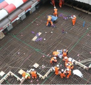
The number and cross section of earth mat terminations needs to considered from a pessimistic point of view. Once the concrete is poured into the base slab and piles, there is no further access to the earth mat. There need to be sufficient numbers of earth mat terminations (including spares!) to provide for a design life of 120 years and sufficient cross section to cater for the worst-case fault current. Electrical designers of the earth mats need to consider cable sizing not just from an electrical perspective but from a mechanical perspective as well – consider that the base slabs are 3m to 5m thick and the earth termination cables will pass through the whole depth of the base slab. The cables need to have sufficient mechanical strength to withstand the weight of the concrete during the concrete pour and the fixing need to be able withstand the vibration. Experience at an early stage of the construction phase of the Elizabeth Line show a considerable of last-minute interventions were required prior to concrete pours, demonstrating that there was a general lack of experience with construction firms of using foundations as earth mats. See Figure 1 which gives an idea of the huge scale of just one of the (many) Elizabeth Line earth mats.
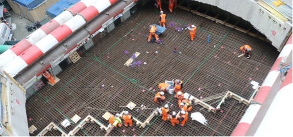
Figure 1. Whitechapel Earth Mat Installation
Post construction of the earth mat, the next lesson learned was around the protection of the assets – two problems persisted across the project. On some sites, pockets were cast into diaphragm wall sections to expose access points to the earth mat and lightning protection points, however, post construction these could not be relocated. On other sites, 300mm2 cables for earth mat terminations were left protruding from the concrete base slab, these became severely damaged and suffered water ingress into the sheath. On any future project, earth mat termination design needs to consider how the earth mat termination will be protected. The best installation utilised earth bar pits that were cast into the base slab (see Figure 2) and would be recommended for any future projects. There is minimal cost for the provision of the pits and any additional cost is by far outweighed by the potential cost of remedial works.
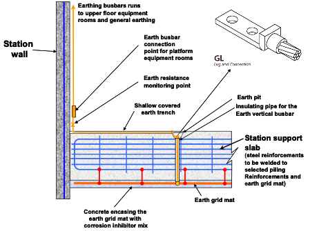
Figure 2. Use of earth pits in base slabs
Earth Zoning
Earth Zone Design
The interface between the routeway and the SSPs needed to be carefully managed. Two areas needed specific management and these were (1) the step and touch voltages at the interfaces between the routeway and the SSP infrastructure, in particular, platforms, and (2) the management of traction current flowing into SSP infrastructure.
At the time of design (circa 2008) of the Elizabeth Line earthing system, there were no industry or national standards that set the requirements for a 25kV AC autotransformer electrified railway, or that dealt with 25kV electrification in deep tunnels in a metro setting. This has now been better addressed by the latest release (Revision 4) of NR’s AC earthing specification NR/L2/ELP/21085[3], however, from the Crossrail project there are further lessons learned that could be applied to future 25kV AC traction below ground metro projects.
The principle applied at the interfaces between the routeway and SSP sites was to keep the routeway earth system separate from the SSP earth zone and bond the two earth systems together just at a single location to ensure both systems are at the same potential. This has the effect of preventing traction current entering the MEP earthing system. The reason for preventing traction current from flowing in the SSP MEP earthing systems is to remove the need to increase the rating of the MEP small wiring to cope with traction return currents. See Shaft and Portal typical earthing arrangement in Figure 3.
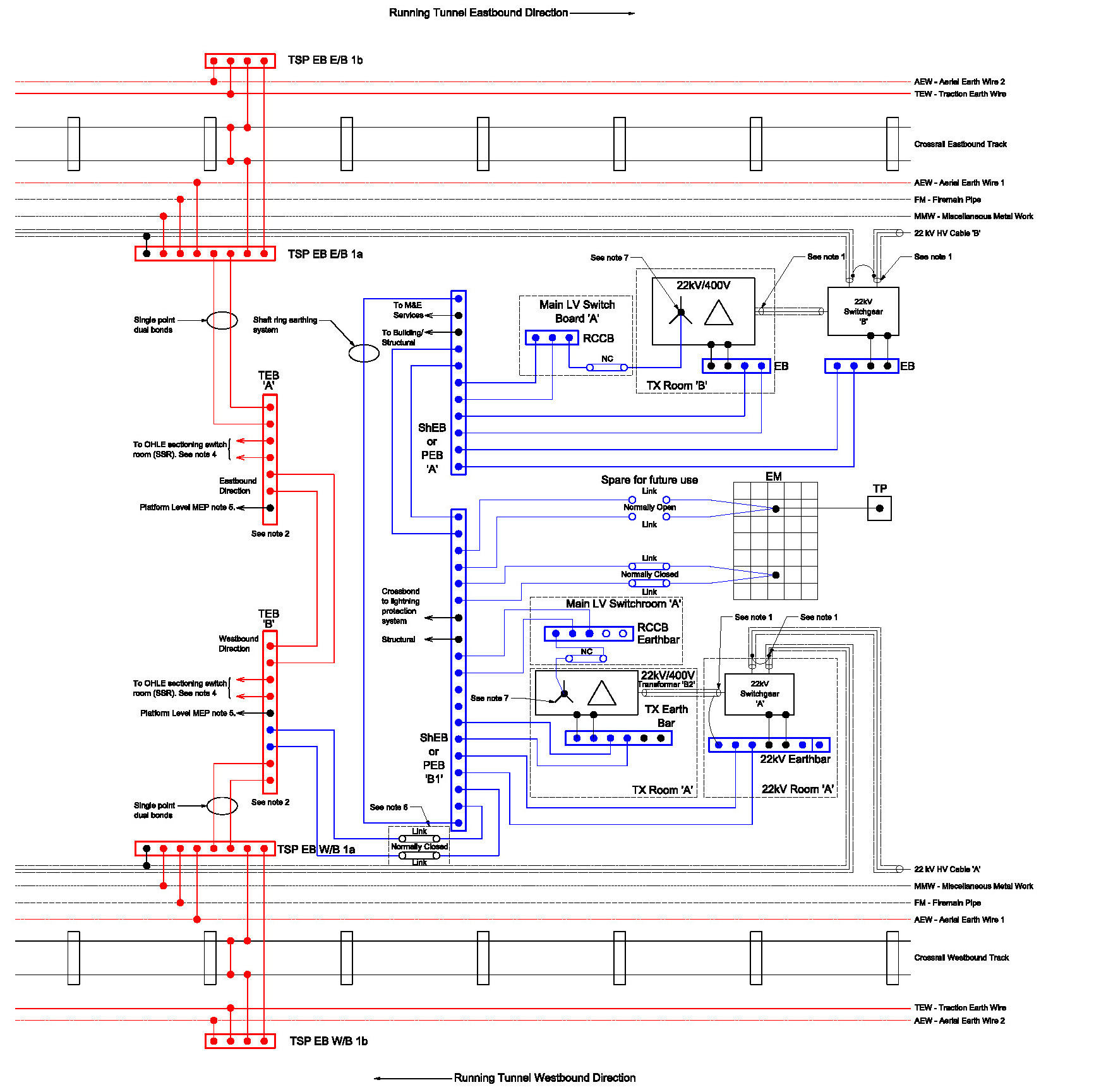
Figure 3. Typical Shaft/Portal Earthing arrangement (traction shown in red, MEP in blue)
Testing and Design Changes
It was found during installation and testing that the insulation levels that were desired between earth zones were not being achieved. The primary reason why the separation between earth zones could not be achieved was that both the routeway and SSP have metallic infrastructure (such as cable management systems) fixed to the reinforced concrete structures in which they are mounted and are hence “fortuitously” connected via the steel reinforcement.
The design of the earthing zones was amended so that the equipment located in the platform zones at a station was bonded to the traction earth in compliance with RSSB standard GL/RT1255[4] (as was in force at the time, standard now withdrawn). By bonding the loads at platform level to the traction earth, any traction current had an adequately rated return path. A number of locations were considered for the transition between the station and traction earth zones, but by far the easiest location to implement the interface was at the bottom of the escalator barrel – on investigation it was found that that all stations had supplies to all services in the escalator barrels from above.
Zoning Lessons Learned
In any future project, by far the easiest way to implement separation between routeway and station earth is to place the whole of the platform level to traction earth and create the boundary to station MEP earth zone at the escalator barrels, stairs and risers.
The separation between the traction and MEP earth zones at SSP’s was found to be highly effective in preventing traction current from entering into the SSP earth small wiring. Touch voltages were also found to be less than 5% of those allowed under BS EN 50122[1].
Stray Current
AC Stray Current – Impact on Railway and adjacent infrastructure
The traction return current on an AC railway is provided with a dedicated return system – in the case of the Elizabeth Line, this is formed from two running rails, two aerial earth wires and the tunnel earth wire. The eastbound and westbound lines are cross bonded at regular interval including stations (both ends), shafts, portals and cross passages. Unlike surface railways where the traction system is earthed at the traction substation and via the overhead line structures; the Elizabeth Line only has a direct connection to earth at traction substations and SSP’s.
There are a number of parallel metallic systems in the Elizabeth Line routeway that are bonded to the tunnel earth wire, these include fire mains, pumped drainage pipes, cable management systems, and the latterly the emergency evacuation walkway.
The traction return system is cross bonded to the SSP MEP systems at a single point at each location, both the SSP and Traction systems are connected to earth at this point. This references the traction system to earth at that point and ensures that all electrical systems are at the same potential.
There was a concern that due to the unconventional approach to earthing the traction systems with relation to the inaccessibility / remoteness of the earth, that more traction return current would cross into the SSP locations to go to earth. On a normal surface AC railway, 30% of the traction return current will travel through the earth to get back to the supply point. The concern for the Elizabeth Line was that traction return current would attempt to use the MEP small wiring and sub-main earth conductors which were not adequately rated for traction return; and where traction current flowed in MEP cable armour, the cable would be de-rated.
To further exacerbate the concern, a number of the Elizabeth Line stations had a direct interface and shared facilities with other railway companies with different types of traction / MEP power configurations including Network Rail (NR), London Underground (LU) and Docklands Light Railway (DLR) – over multiple sites e.g. LU’s Central Line at Stratford, Liverpool St, Tottenham Court Road, Bond Street and Ealing Broadway.
The concern from the adjacent railways was that as they were parallel to the Elizabeth Line, that AC traction return current would use their infrastructure to return to the Elizabeth Line traction feeder stations, rather than the planned path. The adjacent railways were rightly concerned, for whilst AC stray current does not cause corrosion to steel like DC stray current, it can have impact on signalling and communication systems, also adding complexity to isolations during maintenance.
For the Elizabeth Line interfaces, AC stray currents were a concern for LU and NR signalling systems. A complex simulation model was constructed to determine the flows of AC stray current from the Elizabeth Line into the adjacent railways as shown in Figure 4 (image from the modelling report).
Figure 4. Elizabeth Line Traction Earth System Model
The modelling of the earth paths was vitally important at a very early stage of the Elizabeth Line project, because if modification of the LU or NR signalling systems was required, the minimum time for implementation would be circa 2 years – the works would have to be done to third party infrastructure before energisation of the Elizabeth Line to ensure safe operation of the existing infrastructure was maintained. The modelling allowed for targeting the signalling track circuits that were likely to be affected.
Modelling of the earth paths had previously been undertaken for the electrification of the Great Western Railway in the 1990s and again in the 2000s for the introduction of the Heathrow Terminal 5 spur. The historical model captured the Great Western Railway and the LU lines west of the Circle Line. On energisation of the 25kV traction system on the Great Western and the Heathrow Terminal 5 extension the model was validated to 5% to 10% accuracy during commission testing.
The Great Western Railway is located on the edge of central London and has fairly simple interfaces. The Elizabeth Line is located in the heart of Central London and has complex interfaces, whilst Figure 4 shows the known rail interfaces, there are many other unknown parallel paths that cannot be identified (such as for example: gas mains, electricity network cables, LU running rails, LU Central Line spherical graphite iron tunnel linings).
Due to the unknown interfaces and the significant reduction of resistance between design and installation of the Elizabeth Line traction return path the model turned out to be extremely pessimistic. The pessimism can be explained as follows:
- The initial model had assumed that the earth mats would have achieved a resistance to earth of 1 Ohm whereas the actual value achieved averaged 0.1 Ohms.
- The return path within the Central Section of the Elizabeth Line reduced dramatically during design development; considerably more metallic cable tray was installed, the HV cables were installed onto a large horizontal metal cable ladder and the longitudinal evacuation walkway was changed from concrete to an aluminium construction that itself had a resistance of 5 micro-ohms per metre (which is more conductive than the special composite conductor rail used on LU’s Jubilee Line).
- The earth segregation zoning at station, shaft and portals was more effective than had been considered possible. The insulation between the zones whilst only achieving insulation levels in low orders ohms (worse than anticipated), was much higher when compared to the resistance of the combined routeway return path in the order of low milli-ohms, in actual use, over 95% of the traction current has been kept within the Elizabeth Line routeway, whereas, typically 70% is kept within the routeway of a conventional AC railway.
- Fortuitous connections between concrete screws holding the routeway CMS and overhead Line structure made contact with the reinforcement in the piles and diaphragm walls of the shafts at station, shafts and portals giving a much greater connection to earth than had been envisaged.
Segregation of Different Traction Systems
Where DC traction railway lines run parallel with AC traction systems above ground, it has been preferred where possible to keep the AC and DC traction systems segregated; for the Elizabeth Line, this was the case with NR at Abbey Wood and the DLR. The reason for the separation is to remove the risk of DC stray current corrosion to the overhead line foundations and structural concrete in the Elizabeth Line stations and retaining walls. Additionally, insulated fences were installed along the long boundary to prevent the risk of touch potentials that might be experienced between the two railways.
During testing of the Elizabeth Line AC overhead line traction system it was established that whilst the two systems are insulated from each other, the insulation resistances measured had similar values to the resistance of the soil. This was deemed acceptable because the signalling systems installed at Abbey Wood / on DLR at the time of Elizabeth Line trial running were immune to 50Hz AC traction return currents.
DC Stray Current Issues
The prevention of DC stray current where AC traction systems interface with DC third rail electrified railways is essential. Two specific requirements need careful consideration – (1) prevention of the flow of stray current and (2) the mitigation of touch voltage.
The best method of controlling DC stray current is at source, and any other treatment can only be considered as mitigation of the symptoms of stray current. Any treatments that are required to mitigate DC stray current corrosion need to be included with the civil structures at the design stage as it very difficult to add measures later.
At the Custom House Station interface between DLR and the Elizabeth Line, insulation between the two infrastructures was designed into the two pedestrian bridges that link the two adjacent stations. During testing, even with all utilities isolated, disappointingly, the insulation resistances were only approximately 1 Ohm, which is very similar to the resistance of the Elizabeth Line earth mat. Both the Elizabeth Line and DLR stations are piled and both use the piles for system earthing for their respective infrastructure; it was concluded that both infrastructures were connected through the soil itself.
The only way to have increased the insulation resistance between the two adjacent stations would have placed further insulation into the Elizabeth Line structures, or to have decreased the resistance of the DLR traction return.
DC Stray Current Lessons Learned
The lesson learned is that future projects need to design in stray current mitigation into the civils stages and not wait for the MEP design which often lags in the programme.
Recommendations for Future Projects
Considering the Elizabeth Line earthing system as a whole over the 10+ years it has been in construction, the following recommendations for future projects are made:
- Earth mat designs need to be completed prior to the commencement of civil construction to ensure that the reinforcement is installed to meet the requirements electrically. It is essential that sufficient evidence is recorded of the earth mat to allow the earthing specialist to assure the design and the MEP/ routeway fit out contractors to accept the earth mats.
- Earth mats need to be tested prior to and post preliminary civils construction to ensure that the necessary earth resistance is achieved, and that all cables and connections remain intact.
- Cast in earth mat termination pits should be cast into the base slabs to prevent damage the earth mat tails.
- Due to the low resistances achieved by structural piles and diaphragm walls, earth mats should be created from these in preference to earth mats created from driven rods – see Figure 5 for the design at Canary Wharf station.
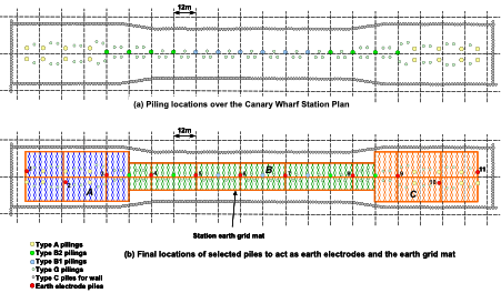
Figure 5 – Canary Wharf Station earth mat design using structural piles
- A much better understanding of the traction return circuit is required with respect to the parallel paths; metal tunnel walkways and CMS have a very large impact in the reduction of the resistance of the routeway return path, and directly affect the levels of AC stray current, which in turn reduces the amount of current exported to neighbouring railways.
- Insulation levels between earth zones and neighbouring railways are likely to be very low, particularly where both parties are using buried metallic structures and piles as earth mats. The insulation resistance could be as low as the resistance of the soil itself.
- With evidence gathered from the construction of the Elizabeth Line, much lower target resistances for earth mats and return paths could be included in construction speculations as there is sufficient evidence that these low resistances can be repeatedly achieved.
- Earth zones may be able to be reduced and simplified in SSPs if the impedance of the routeway traction return can be reduced to ~100 times lower than the impedance of the paths through the station.
Acknowledgements
Sarah Dale, Electrical Engineer Earthing and Bonding, Chief Engineers Group, Crossrail Ltd
References
[1] BS EN 50122-1:2011+A4:2017 Railway applications. Fixed installations. Electrical safety, earthing and the return circuit. Protective provisions against electric shock
[2] BS 7430:2011+A1:2015 Code of practice for protective earthing of electrical installations
[3] NR/L2/ELP/21085 Revision 4 Earthing and Bonding on A.C. Electrified Railways
[4] GL/RT1255 Revision 1 Low Voltage Power Supplies in Electrified Areas
-
Authors

Malcolm Anderson BEng(Hons) CEng MIET
Malcolm is the head of discipline for earthing and bonding in the Crossrail Chief Engineers Group since 2014. He is responsible for the earthing and lightning protection of all of the stations, shafts and portals as well as the running tunnels. He has under taken similar roles on the Heathrow Express, Terminal 5 Stations, Western Dedicated Freight Corridor in India, East London Line and Manchester Metrolink.
He entered the programme in 2009 as part of the design team for Liverpool St Station enabling works, and supervised the construction of the enabling works including relocation of a traction substation, and station electrical switch rooms. He then moved to a role as Head of Electrification for Rail for London for the Crossrail routes in 2013 and oversaw the review of electrification and EMC for the Crossrail Central Section.