Elizabeth Line Earthing Electrode Testing Lessons Learned
Document
type: Technical Paper
Author:
Malcolm Anderson BEng(Hons) CEng MIET
Publication
Date: 02/12/2021
-
Read the full document
Introduction
This paper details the lessons learned from the re-test of the earth mats (installed in earlier stages of the project) prior to first energisation of the 25kV electrification system on the central operating section (COS) of the Elizabeth Line.
Also outlined are some of the methods for earth and earth mat resistance measurement and the practicality of these methods in an urban environment and on projects with linear integrated infrastructure is examined.
Background
The COS of the Elizabeth Line is constructed predominantly below ground in bored tunnels that are lined with segmented concrete rings. There is no direct contact with the Earth for systems located in the tunnel. Earth mat systems have been installed at every station, intervention shaft and portal (SSPs), feeder substations and traction substations. Earth distribution wires have been installed along the track (referred to as the routeway) connected to the earth electrodes. All lineside/tunnel systems are bonded to the earth distribution wires. Earth distribution rings are installed within the SSP locations to provide a connection to earth for all Mechanical, Electrical and Public Health (MEP) equipment.
During the construction and commissioning of the earth electrode systems across the Crossrail project it was easy to undertake measurement of the SSP’s earth mats immediately post construction because the earth mats were semi-exposed, hence cable tails / earth rods were easily accessible and not integrated to larger structures and systems.
As the various Contractors commenced fit out of the SSPs and routeway, the earth mats within the civil elements were connected deliberately to the earth distribution network and cables, but unintended fortuitous connections were also made between the structural reinforcement used in the civils construction and the MEP assets. The fortuitous connections for each element are detailed later in this document. It was intended that individual earth mats should be able to be separated from the earthing network via test links, however, due to the fortuitous connections in many sites this is not possible as even with the test links open, connections to the earthing network and other earth mats remain in circuit.
The issue became further compounded once the routeway systems were installed, as the routeway systems have connected the SSP earth mats, SSP earth networks and routeway earth systems together both deliberately by cable and also fortuitously by fixing metallic assets into the structural reinforcement, which has resulted in the Elizabeth Line COS becoming one single integrated earth network. Even this became further complicated as the COS earthing system is fully integrated with Network Rail’s earthing systems at Pudding Mill Lane and Westbourne Park, additionally via connections to the London Underground (LU) earthing systems at Paddington, Bond St, Tottenham Court Road, Farringdon, Liverpool St and Whitechapel Stations.
At re-test of the mats prior to first energisation it was found the original tests (carried out at installation of the earth mats) were not repeatable, as the element under test had increased in size to such an extent due to the level of integration that it was no longer possible to conduct the measurement outside the zone of influence. In many cases, it was also impossible to cross major roads with test leads or find access to open ground that had undisturbed soil.
Therefore, to re-test the Elizabeth Line earthing systems an alternative approach was required to prove the health of the earth electrodes and the earthing distribution network, and that approach is set out in this document.
Importance of Maintaining Earthing Values
The Crossrail Earthing and Bonding Strategy set out the design requirements for the earthing mats as follows:
- Stations, Shafts and Portals to have an earth mat impedance of 1 Ohm or less
- Auto Transformer Stations (ATS), and Sectioning Auto Transformer Stations (SATS) to have an impedance to earth of 1 Ohm or less
- Auto Transformer Feeder Stations (ATFS) to have an impedance of 0.5 Ohms or less.
At the outline design stage the traction system was modelled using the earth mat impedances as set out in the earthing and bonding strategy. It was confirmed that the predicted short time step and touch potentials met the requirement of BS EN 50122[1] and were just below 645V; additionally, the Rise of Earth Potentials were acceptable.
Post construction of the SSPs, SATS, ATS and ATFS locations the earth mats were measured and found to have significantly lower resistances to earth than those required by the earthing and bonding strategy. These values were then used to update the traction power, non-traction HV and LV power models. This demonstrated significantly lower step and touch voltages than those predicted at outline design.
The revised models were validated by testing during commissioning. The commissioning tests confirmed that there was a very significant safety margin between step and touch voltage limits in BS EN 50122[1] and the value measured.
It is important that regular periodic measurements are undertaken to ensure that there is no significant shift in earth mat resistances and that the integrity of the earth distribution network remains as designed as the earth system provides fundamental life and fire safety. The maintainer should record and monitor the earth mat resistances over the planned service life, as long term trend data can be useful to determine remaining life / identify issues. The maintainer should note that a change in earth mat values above the strategy limits will increase the risks on site and potentially make the systems unsafe.
Elizabeth Line Provision of Earth Mats
The Elizabeth Line had two different general approaches for provision of earth electrode mats. At smaller shafts and portals locations it was possible to install a number of earth rods around the perimeter of the building. At the larger portals, shafts and all stations reinforcing steel within piles, structural concrete and earth tapes below base slabs were used as the earth electrodes.
The mined stations are constructed with reinforced concrete shafts at either end of the station to house the station entrances plus MEP equipment and then a spray concrete tunnel was constructed between the two shafts to house the platforms.
Each mined station has two earth mats, constructed under each of the shafts. The earth electrodes were formed from earth tapes below the base slab plus the reinforcement in structural barrettes and piles. Some of the diaphragm wall sections were allocated for lightning protection down conductors and others for use as connections to earth for over station developments.
At the design stage it had been envisaged that the earth electrode in one shaft would be independent of the earth electrode in the other, hence allowing for independent testing of the mats, and that this would be maintained as the spray concrete linings were designed to be reinforcement free.
At the sub-surface box stations, a similar approach was taken using the central plunge piles for earth electrodes, with the perimeter diaphragm wall piles for lightning protection and over station development earth electrodes. During construction, the reinforcement within the diaphragm walls and the plunge columns was connected to the reinforcement within the base, roof and intermediate floor slabs. The net result is that all of the reinforcement is electrically integrated together.
For the surface stations and box stations it was possible to test individual piles or diaphragm walls at the early construction stage, however, as construction progressed civil components become integrated and electrically connected into a single entity.
Earth Electrode Testing
The preferred earth electrode test method on the Crossrail project was either the fall of potential slope test or the fall of potential 61.8% method.
The fall of potential test is conducted with a three terminal digital earth tester. The choice of the tester for large structures such as the Elizabeth Line SSPs is important. The digital earth tester should have the capability to measure to a resolution of 0.001 Ohms plus be specified for large earth systems and noisy environments. For the Elizabeth Line, the preferred tester was the Megger DET 2-2, other earth testers in the Megger range were not suitable due to their limited range and inability to discriminate against noise (alternative Digital Earth Test instruments produced by other manufactures are available with similar capabilities).
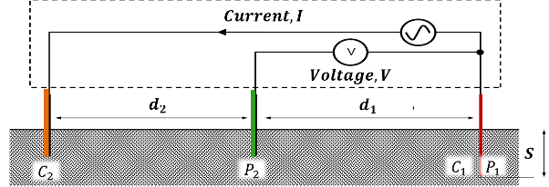
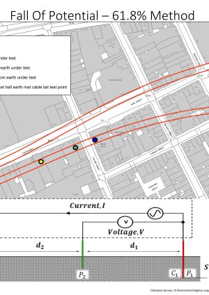
Figure 1. Fall of Potential Test Electrode Arrangement
The fall of potential test set up is shown in Figure 1. To achieve a realistic measurement the test electrode C2 need to be placed as far from the earth electrode as practically possible and at a distance (from the electrode being tested) of a least 10 times the depth of the earth electrode under test. The measurement electrode P2 is then moved in a line between the electrode under test C1 P1 and reference electrode C2 at 5m increments if a slope test is being conducted. The resistance readings from the digital earth tester DET 2-2 are then plotted on a graph of resistance against distance. See Figure 2 for a typical earth test resistance curve.
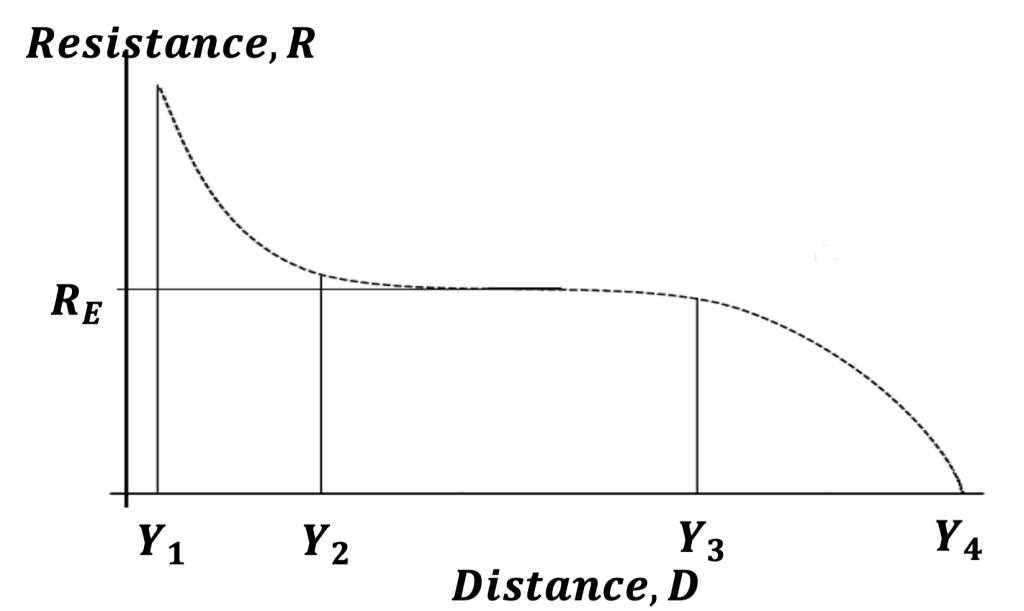
Figure 2. Typical Earth Test Resistance Curve
The first part of the curve between Y1 and Y2 is the zone of influence of the electrode under test. The plateau of the curve between Y2 and Y3 is where the true value of the resistance of the earth electrode can be found. Typically, the true value of electrode resistance is located at 61.8% of the distance between Y1 and Y4.
If a slope test is impractical due to difficulty in having access to good ground to drive test electrode P2, the 61.8% test can be conducted by placing the P2 electrode at 61.8% of the distance between Y1 and Y4 and then taking additional readings about 5m either 61.8%, as long as the readings are similar.
In the case of the Elizabeth Line, immediately post construction it was possible to test individual piles within the boundary of the construction site as the distance from the pile to the refence electrodes typically only needed to be 300m.
As the construction progressed and the piles became integrated in the reinforced shaft structure, the effective length of the earth electrode increased, resulting in increased distances between the electrode under test and the reference electrode for the fall of potential test. This becomes a particular problem in the dense urban environment of London as there is little access to the soil for reference and measurement electrodes; and where there is access, there are underground obstacles that can skew the measurements. The problem is further compounded by the safety and logistical risks of temporary cables (to enable the testing) being laid on the ground in the urban realm and across major roads.
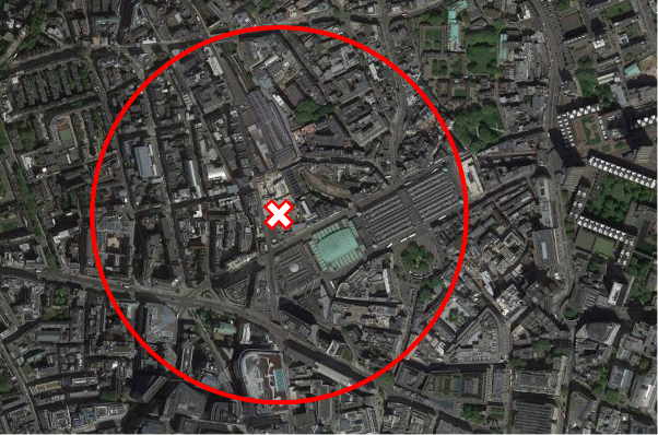
Figure 3. Farringdon Station (Western Ticket Hall) Location and minimum 300m test distance
The circle in Figure 3 shows a 300m radius around the earth mat located in the western ticket hall at Farringdon station. The site is fully enclosed within four major arterial roads which were near impossible to cross with test leads. The few pockets of open ground within the circle were found to be within the zone of influence once the station was constructed and fitted out. Any green space outside of the circle was either inaccessible as it was private land or had structures such as underground car parks below, which rendered the space unsuitable for use.
This problem was partially resolved (for some sites) at the early stages of construction by using the 61.8% fall of potential method and placing the measurement / reference electrodes through the grout holes in the segments in the running tunnel. Upon completion of the test the test reference electrodes were removed and the openings re-grouted. This gave a particularly good result as the tunnels are between 25m – 50m below the present surface and the ground is largely undisturbed and free from obstruction that may impact the test readings. Figure 4 shows the planned test probe layout using the running tunnel grout holes for testing Tottenham Court Road western ticket hall earth mat, as there is no accessible land available which is suitable to conduct tests in the normal way. Future similar projects should be give strong consideration to leaving the test electrodes in place in the grout holes to allow for future maintenance measurements to be taken.
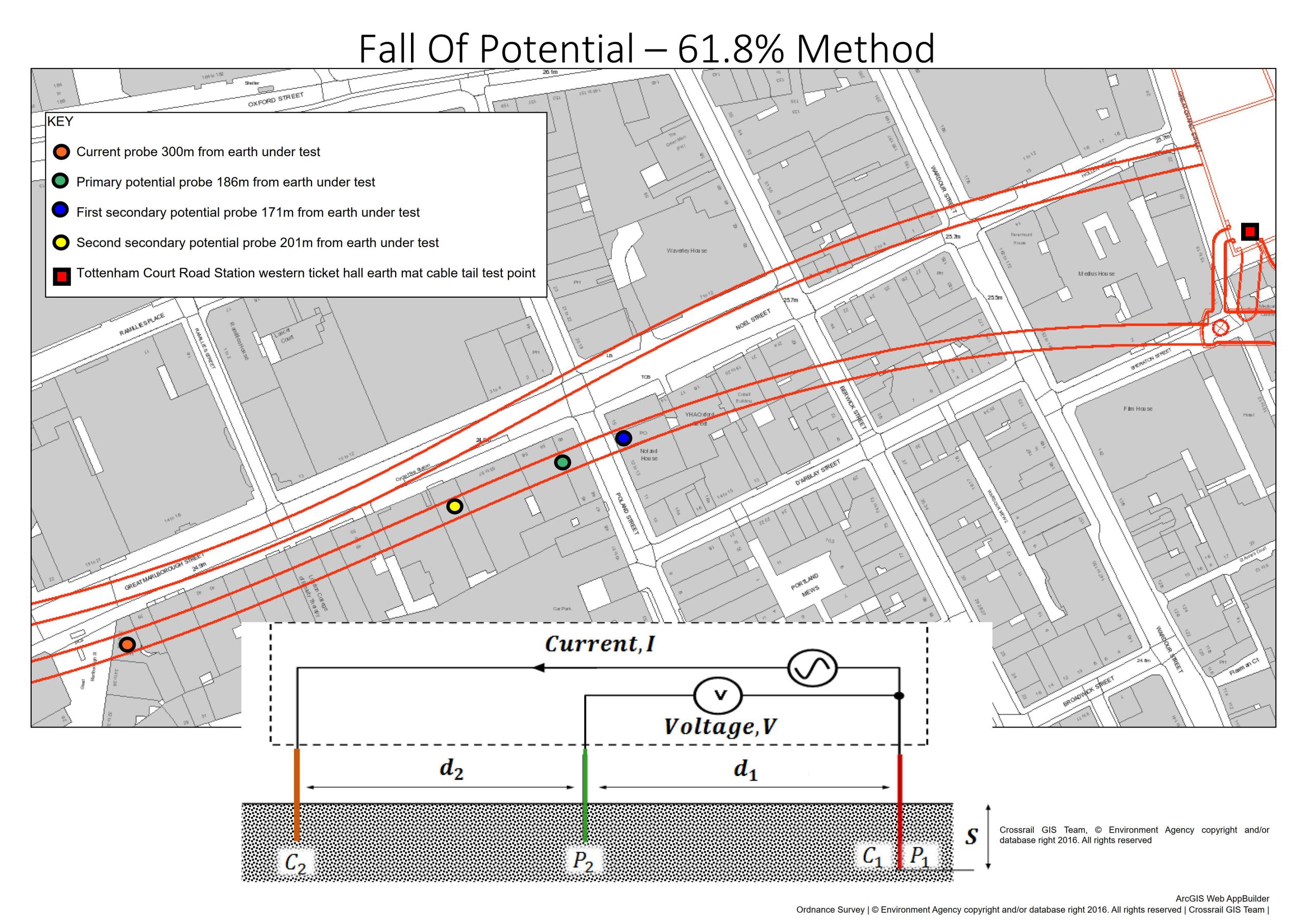
Figure 4. Earth Test Probe Layout in Running Tunnel Grout Holes for Tottenham Court Road Station Western Ticket Hall earth mat testing
Source of Fortuitous Earthing
Once the SSP MEP fit out commenced, the cable management system (CMS) and other mechanical services were fixed to the structure using metallic fixings. These fixing were sufficiently long enough to make contact with the structural reinforcement which had the impact of electrically interconnecting reinforced concrete structures and therefore making a fortuitous earth path. In particular, at the mined stations this resulted in the east and west shafts becoming permanently connected together and negating the facility to take one earth mat out of service whilst the other remained in service.
The problem became further exacerbated when the routeway fit out commenced. The routeway CMS and electrification equipment was fixed to the reinforced concrete structures at the SSPs using concrete screws that were designed to cut into the reinforcement, resulting in multiple connections between the routeway linear earth distribution network and the SSP reinforcement. Once the routeway fit out was complete the SSPs were permanently integrated together and there is no means of wholly disconnecting any one earth mat that uses the structural reinforcement as part of its components for an independent test.
The final status for the Elizabeth Line earthing system is that it is impossible to measure the resistance of an individual earth mat as there will be a contribution from all sites through the routeway earthing distribution network. If there is sufficient open ground around a SSP location (which is rare) a fall of potential test is possible, however, the measurement result needs to be interpreted as it is not the resistance of the earth mat to earth, it will be a measurement of the (whole) earth system to earth at that point. It should be noted that from the measurements taken throughout construction it is apparent that the resistance of the earth mats and the resistance of the integrated system are not greatly different.
Construction Risks
Where structural reinforcement within piles is used as earth electrodes, there is a risk of corrosion of the steel in individual reinforcement bars, which reduces the effectiveness of the earth electrode. This problem is unlikely to occur on the Elizabeth Line as the concrete structures are very large and contain a vast amount of large diameter reinforcement bar. There is a very low risk that corrosion of the structural reinforcement would render the earth electrode inoperable. If there were to be significant corrosion that could render the earth electrode inoperable this would become apparent due to the cracking and spalling of the concrete.
One area of concern where knowing the earth mat resistance does provide benefit and regular testing is required, is the mitigation of the corrosion of the earth mat cable tails and the clamping arrangement to the reinforcement bar. These earth cable connections cannot be visually inspected as they are cast into the concrete. The only practical method of testing in this scenario is to conduct loop resistance tests between earth mat cable tails. Each earth mat has a minimum of two cable tails and two spare tails. It is possible to conduct a loop resistance between each tail and the others. These readings should be recorded and reviewed against previous tests. If there is an increase in readings over a period of time this is an indication that the cable tails or their connections are deteriorating. Remedial works such as swapping to spare healthy cable tails or major civils works to install new tails can be planned and executed before the deterioration becomes severe and impacts the integrity of the earth mat system.
It is vital that the earth mats are designed at the same time as the civil structures. As part of the design, it is vital the testing methodology is developed early in the design process and any facilitating equipment required to conduct the tests such as permanent test electrodes within the tunnel rings are included.
Lessons learned
- The importance of measuring the resistance of individual structural elements used as earth electrodes immediately post construction. This allows a fall of potential test to be undertaken with relative ease as the theoretical test distance of 8 x the length of the pile is likely to fall somewhere within or close to the construction site.
- Early tests are crucial to reveal damaged cable tails on connection at a point in time where it is still possible to select another pile or effect repairs.
- Once the rest of the structure is built, piles will become electrically integrated together by the capping beam, future tests will give results for the whole structure not individual piles.
- Once MEP fit out commences, CMS and metallic services link individual shafts at stations together, so that any earth mat resistance test will return values for the resistance of the whole structure to earth.
- Once routeway fit out commences, it is no longer possible to measure the resistance of an individual SSP earth mat alone. The measurement result of any earth mat terminal returns the value of the whole system to earth at the point of measurement.
- For small structures and those using individual earth rods rather than earth mats then it is possible to undertake a fall of potential test within the railway boundary or close urban realm. For the larger structures it become impractical to conduct a fall of potential test as the distance between reference electrode become unrealistic in an urban environment unless reference electrodes are installed in the routeway.
- Appropriate measurement meters need to be employed with a resolution of 0.001 Ohms and sufficient driving current to obtain a stable reading.
Recommendations for Future Projects
- Test structural elements e.g. piles, that are used as earth electrodes immediately post construction, prior to integration into the rest of the structure. This allows an accurate fall of potential 61.8% or slope test to be conducted within the boundary of the site.
- Testing of the individual earth electrode mats and the box stations should be prior to MEP fit out of the SSP and routeway. This allows for the routeway to be used for the fall of potential test using the 61.8% method or the possibility of a slope test in surrounding area.
- It is vital that the earth mats are designed at the same time as the civil structures. Consideration should be given at the design stage into leaving test points in the tunnels for all future fall of potential tests using the 61.8% method. This would consist of solid copper rods driven through the grouting holes in the tunnel segments with suitable water proofing and protection over the test terminals. This allows for consistent measurements that are repeatable over the life of the infrastructure and will be at a similar depth to the earth mat in undisturbed ground.
- At the design stage consideration needs to be given as to the definition of the “The Earth” when it comes to maintenance testing of earth mats. Should the soil be considered as the “The Earth” or should “The Earth” be the structure of the station due to the scale of the structure and the interconnectivity through the routeway? This is a discussion that needs to be considered at industry and standards level, particularly for mega projects and very large structures.
Acknowledgements
Sarah Dale, Crossrail Ltd, Chief Engineers Group, Electrical Engineer Earthing and Bonding
References
[1] BS EN 50122-1:2011+A4:2017 Railway applications. Fixed installations. Electrical safety, earthing and the return circuit. Protective provisions against electric shock
-
Authors

Malcolm Anderson BEng(Hons) CEng MIET
Malcolm is the head of discipline for earthing and bonding in the Crossrail Chief Engineers Group since 2014. He is responsible for the earthing and lightning protection of all of the stations, shafts and portals as well as the running tunnels. He has under taken similar roles on the Heathrow Express, Terminal 5 Stations, Western Dedicated Freight Corridor in India, East London Line and Manchester Metrolink.
He entered the programme in 2009 as part of the design team for Liverpool St Station enabling works, and supervised the construction of the enabling works including relocation of a traction substation, and station electrical switch rooms. He then moved to a role as Head of Electrification for Rail for London for the Crossrail routes in 2013 and oversaw the review of electrification and EMC for the Crossrail Central Section.
