Engineering Design of the Platform Edge Screens for Crossrail’s Mined Stations
Document
type: Technical Paper
Author:
Julian Birbeck CEng MIStructE, Rosemary Smiley MEng, George Stowell BA(Hons) Dipl Arch MA(Dist) MRIAI RIBA, Ed Newman-Sanders CEng MICE, ICE Publishing
Publication
Date: 09/07/2018
-
Read the full document
Introduction
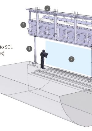
The term Platform Edge Screen (PES) is used in this paper to describe the complete platform edge assembly, comprising platform screen doors, an upper ‘service wall’ supporting lighting, communications, and cabling, plus a smoke-extract duct positioned over the track, as well as the structural frame on which all these elements are supported. The design of the PES has been prepared by the C100 Architectural Component Design package. The scope of C100 covers the fit-out and finishes of all Crossrail sub-surface stations from gate-line to platform. This paper is written from the perspective of C100’s structural engineers. The term PES-frame is used to describe this structure throughout this paper. This PES-frame design applies to five mined sub-surface stations; Bond Street, Tottenham Court Road, Farringdon, Liverpool Street, and Whitechapel.
From street level, the scale of Crossrail platforms, and the associated screens may not be apparent (Fig.1). Given that 9-car Crossrail trains are over 200m long, and each platform has some additional publicly accessible length, to allow for 10-car trains in future, there is over 0.5 km of PES required at each station and the PES-frames described in this paper extend for over 2.5 km in total. Given these dimensions, the PES-frames are edging into ‘industrial’ levels of scale and repetition.
The PES-frame has been designed by structural engineers from a building-design background. Working within the confines of a tunnel-bore, however, is the inverse of what is usual in building design. For a building, the tighter tolerances of the cladding are outboard of the looser tolerances of the structural frame. In the platform tunnels, the large tolerance envelope of the tunnel lining surrounds the PES, which is set out to cladding tolerances.
The PES-frame designers faced the additional challenge of designing a structure that can be constructed and maintained in proximity to moving trains and the 25kV overhead electrification.
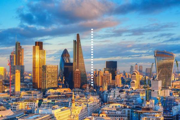
Figure 1. The length of the PES on a typical Crossrail platform
Contractual Set-up
The C100 Architectural Component Design contract is a cross-station design package[1]. Components are drawn, performance-specified, mocked-up, prototyped, and tested as generic engineering, architectural, lighting and wayfinding solutions. One approved, these common design solutions are passed on for station-specific design, integration, manufacture and installation by the main contractors. The Platform Screen Doors (PSDs) including the glazed infill panels are delivered by a separate contract (Fig.2). They are a specialist mechanical element, common to all sub-surface Crossrail Stations.
The role of C100 was not just to produce a detailed design, but also to undertake stakeholder engagement with the organisations that will operate the stations and the railway – namely London Underground and Rail for London. This process involved reviewing design drawings, 3D BIM models, and physical prototypes. As a result, a coordinated Access and Maintenance Strategy was issued to station contractors alongside the RIBA F1 design. In this way, the common components approach created a harmonised maintenance strategy across all mined stations, yielding operational savings throughout the design life of the railway.

Figure 2. BIM model of the PES-Frame reference design
The Purpose of Platform Edge Screens
Platform edge structures are relatively uncommon in the UK. London commuters’ first experience of such structures was with the opening of the Jubilee line extension in 1999. Nonetheless, platform edge structures can be found on many metro systems around the world, and fall into three distinct categories (Fig.3):
- Platform Edge Doors (PED): Balustrade-height edge structures with automatic doors aligned to the train doors. Their sole function is to prevent passengers falling onto the track.
- Platform Screen Doors (PSD): Doorway-height structures with automatic doors aligned to the train. They have the same safety function as PEDs, also providing a degree of screening to passengers from air movement.
- Platform Edge Screens (PES): Platform-to-ceiling structures providing more extensive screening than PSDs, and separating the platform and track environments.
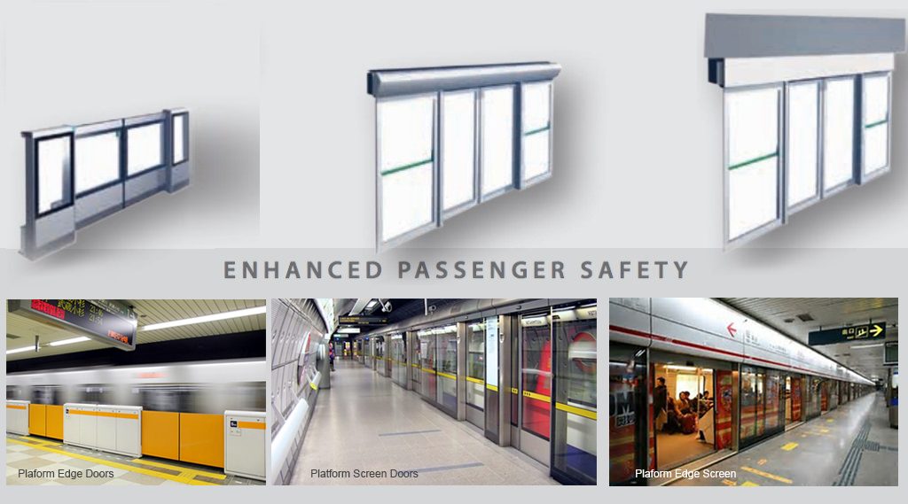
Figure 3. Classification of Platform Edge Structures
For Crossrail, the early decision to use Platform Edge Screens has transformed the tunnel ventilation strategy. In addition to the obvious benefit for passenger safety, tunnel ventilation leakage through stations is eliminated, thereby removing the need for six additional ventilation shafts and head-houses in Central London. Consequently, the PES alone has enabled a major reduction in the capital cost and land-take of the railway.
The simplest approach to platform design would be to collect all station systems on the platform side and all rail systems on the trackside. The stations require extract ducting for the full length of the platform – both for the day-to-day managing of platform ventilation, but critically to provide smoke extract in the event of a fire.
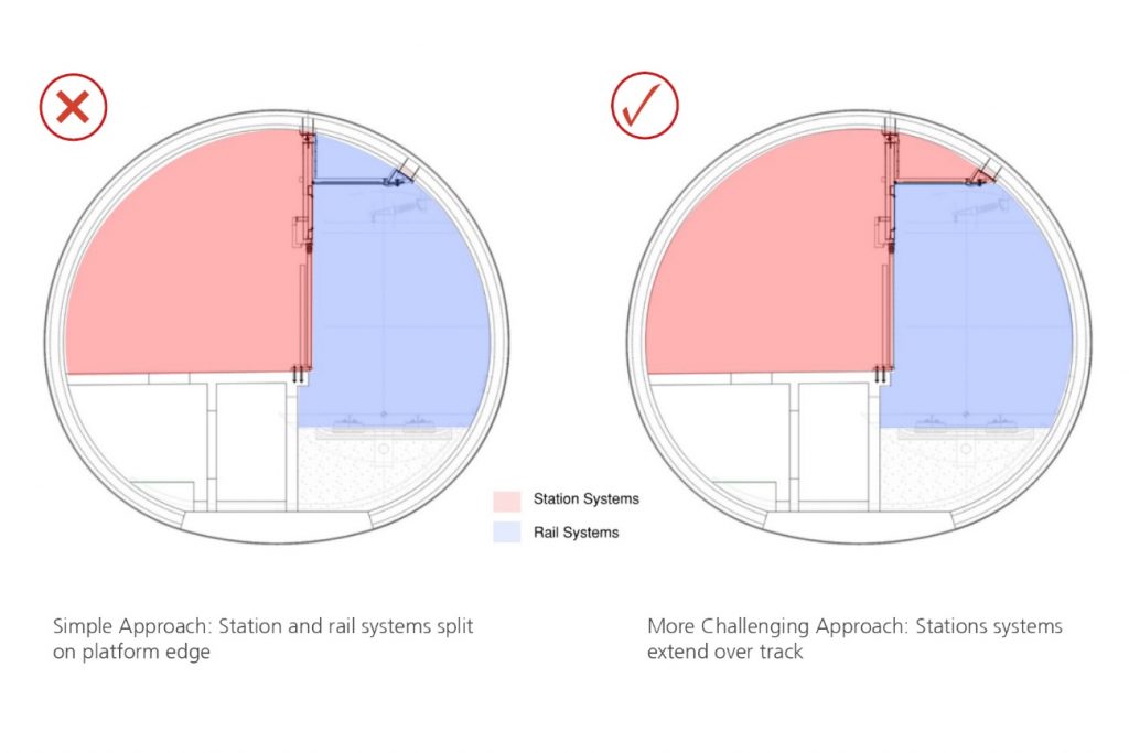
Figure 4. Platform Tunnel Space Planning: Station and Rail Zones
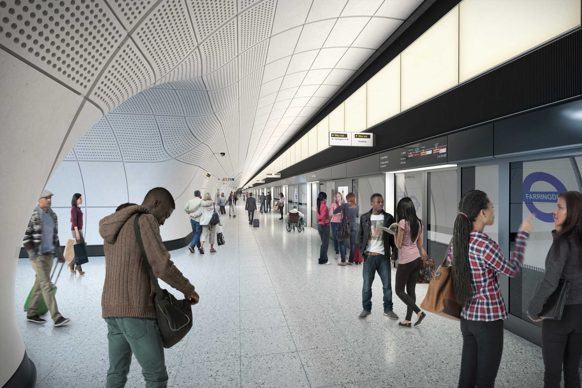
The C100 designers elected to place the extract duct over the track (Fig.4), allowing the platform space to take on a unique character, resulting in a very different passenger experience. The tunnel cladding curves over the passengers’ heads to the apex of the tunnel. All lighting, signage, public address and associated cabling is located on the vertical face of the PES, above the screen doors. Light from the light boxes reflects off the tunnel cladding to create a soft, diffuse ambience – quite different from that created by luminaires suspended above the platform (Fig.5).
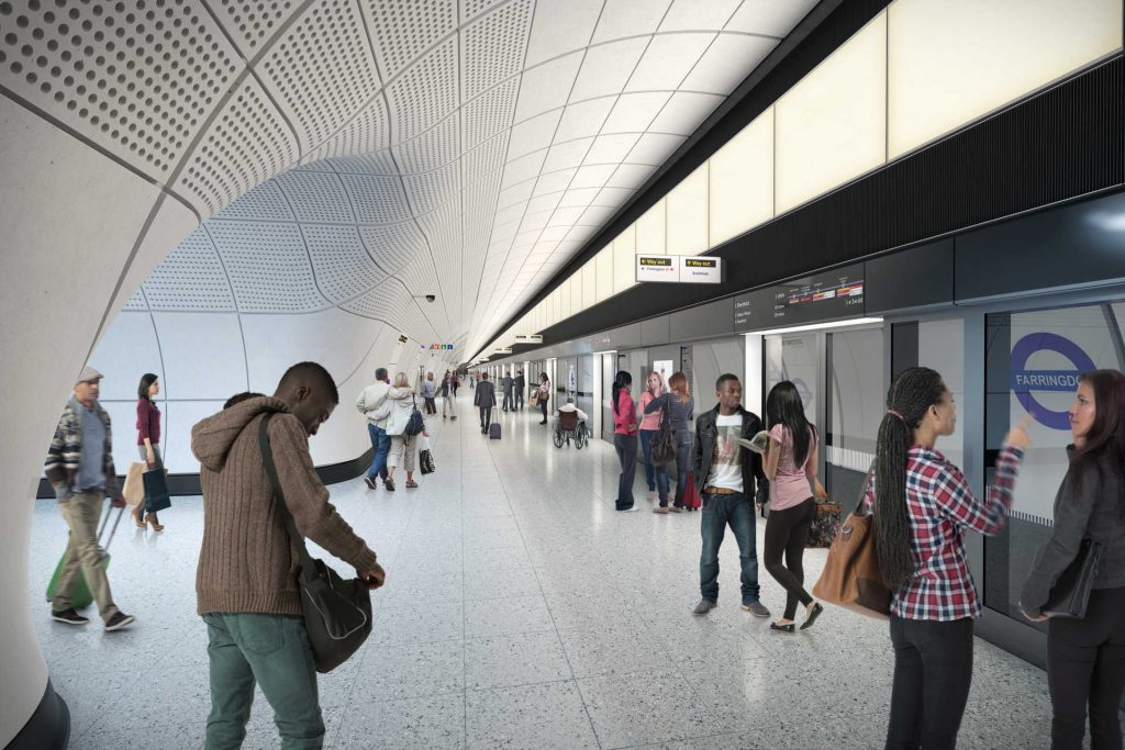
Figure 5. The Crossrail Platform Environment
Consequently, the structural engineer is in a pivotal position; not only designing a structure which is critical to the overall master-planning and land-take of the railway, but which also underpins the architectural concept of the platforms and the passengers’ experience.
Development of the Structural Diagram
The most obvious way to support the PES is to suspend it above the platform screen doors: the PSD provides the screen for passengers up to door height, and the PES frame supports the lighting, cabling and smoke duct above (as well as restraining the head of the PSD).
The construction sequence also suits a suspended structure. During the station fit-out, the system-wide contract passes through each platform. The track-laying plant requires an unobstructed zone along the platform edge, meaning that this straightforward suspended solution could not be used.
The Crossrail mined stations differ from existing tube stations in their use of Sprayed Concrete Lining (SCL). The running tunnels are constructed using a Tunnel Boring Machine, and then the 10.6m diameter platform tunnels are then mined out from the narrower running tunnel bore. The wider tunnel profile is stabilised by SCL (a sprayed concrete mixture, reinforced with fibre[2]).
The concrete spraying process is not suited to the accurate placing of reinforcement. Rebar is used sparingly, only at critical junctions with cross-passages. In addition, the multi-stage build-up of the SCL means that there is a risk of delamination between the layers under radial point loads. As a result, the sprayed concrete lining could not be designed economically with sufficient capacity to support the suspended PES in the permanent condition.
An alternative was to support the PES from below, with posts placed onto the platform edge, however, posts passing down to platform level would need to coordinate with the door positions on the PSD. At the time of design and initial construction of the platform tunnels, the Crossrail rolling stock had not been ordered, and to create a competitive tender, the bid was placed with multiple suppliers, each with different door configurations. Even as this procurement sequencing issue was resolved, there remained a fundamental design requirement to provide future flexibility in the PES, including the option to extend trains in the future, with the same, or different door configuration.
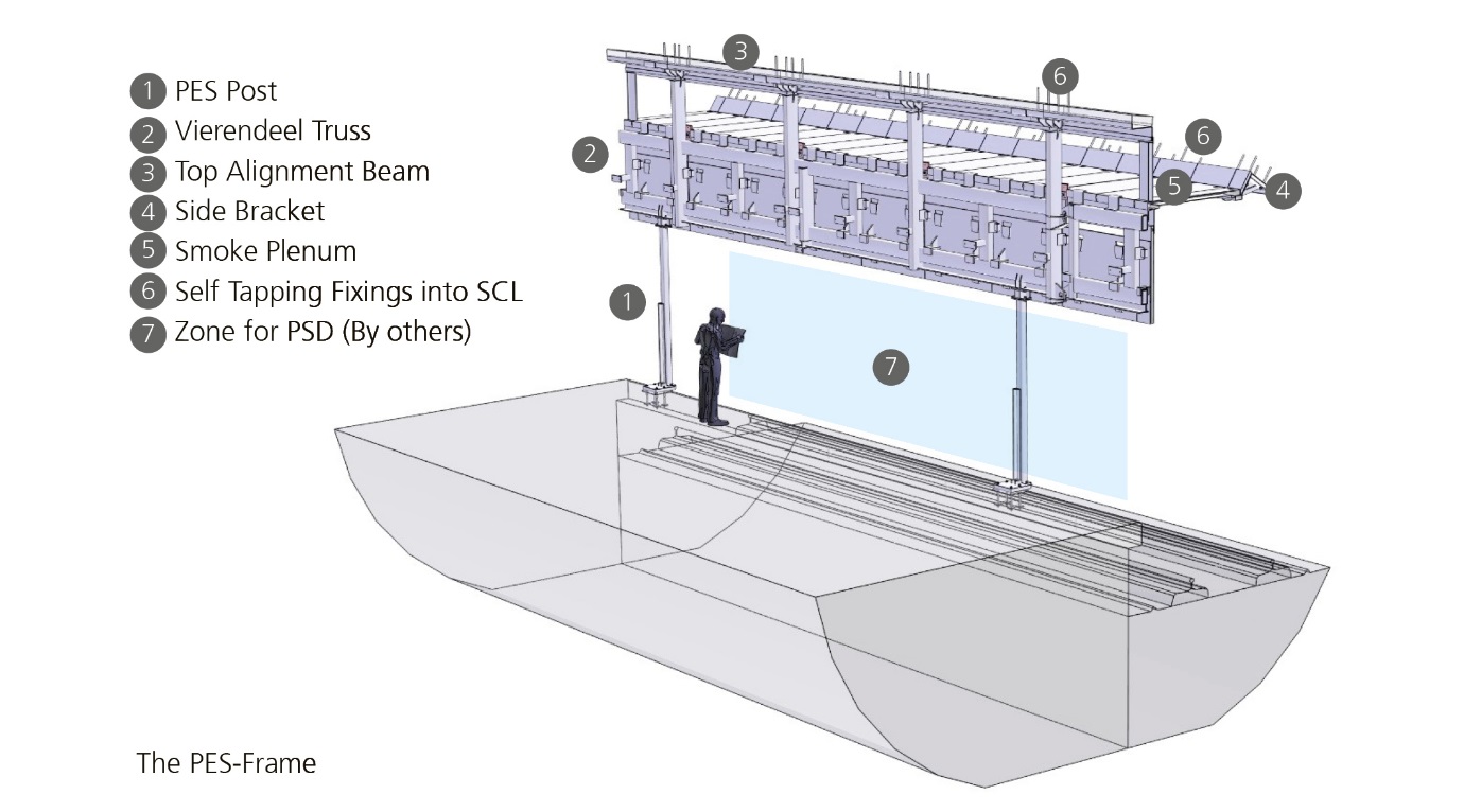
The structural diagram was therefore planned around a sequence of fixings into the tunnel crown at 3m centres. These fixings provide vertical and horizontal restraint in the temporary condition, and switch to horizontal restraint only in the permanent condition (Fig.6). These fixings support a continuous vierendeel truss with a 1.5m module. The vierendeel truss is designed in such a way so that it may be supported at any point with pin-ended posts onto the platform edge below (subject to some basic setting-out constraints). Horizontal props at a 3m module, provide lateral restraint. To complete the system, the smoke duct soffit is formed in precast planks, spanning from the top of the vierendeel truss onto a continuous side-bracket, fixed to the SCL on the track-side.
This structural arrangement provides alternative load-paths, giving the PES-frame an inherent robustness. Should a PES-post be removed, either accidentally or maliciously, the slotted-hole connections at the tunnel crown would reach their limit of travel and the PES-frame would locally revert to a hanging structure in this short-term, accidental condition.
Given the length of the PES, longitudinal movement was an additional consideration. The PES is not fire-rated to withstand a full train fire, but it does need to function in the event of a small baggage fire. To this end, computational fluid dynamic analysis was undertaken by specialists, which confirmed that the PES would need to resist smoke temperatures of 200°C for up to one hour. This temperature does not critically affect steel strength.
Movement joints are provided at 15m centres along the length of the platform, with capacity to take up the resulting expansion in the steelwork.
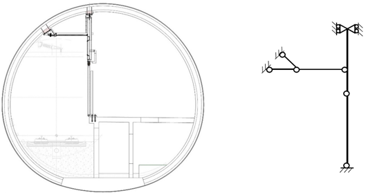
Figure 6. PES Structural Diagram – permanent condition
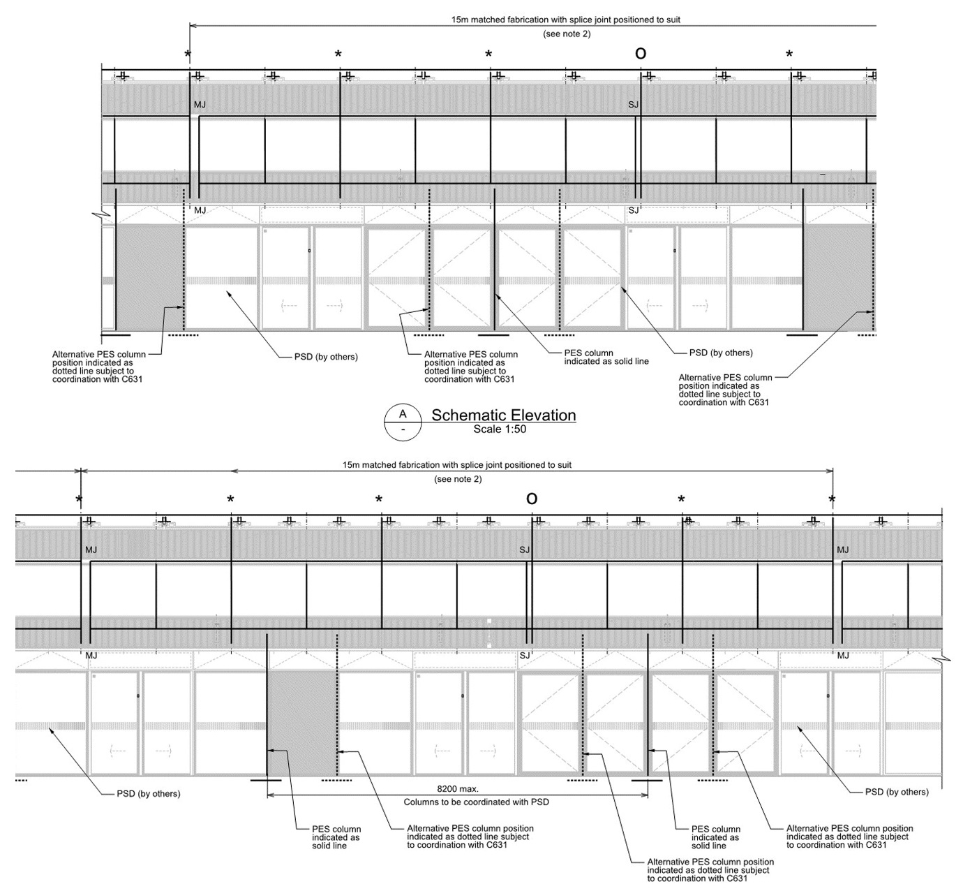
Between these movement joints, it was necessary to provide moment-splices in the continuous PES truss, allowing it to be installed in 3m, 6m, or 9m lengths (Fig.7). The setting-out rules for positioning the PES-posts relative to movement joints and splices were communicated to the station contractors in diagrammatic form (Fig.8). These setting-out rules allowed the reference design to be adapted to any permutation of rolling stock and train stopping position.
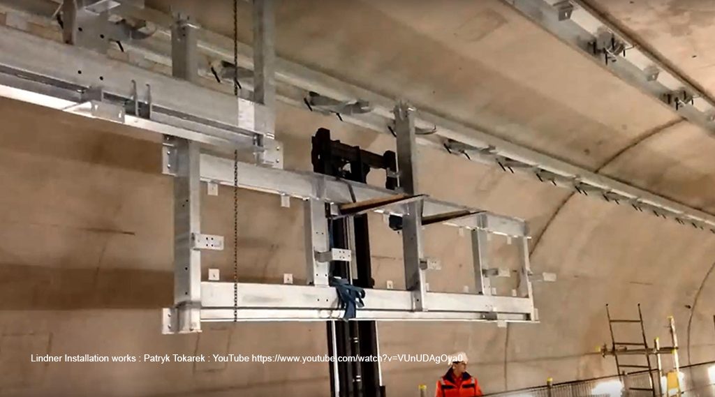
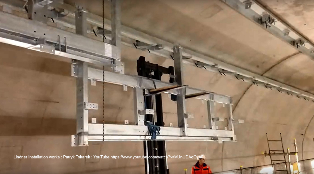
Figure 7. 6m length of PES vierendeel truss being lifted into place at Farringdon Station (note top and side alignment beams already in position)

Figure 8. PES setting out rules communicated in diagrammatic form
Tolerances
The conditions inside the platform tunnels are the inside-out reverse of the normal situation that structural engineers encounter. The SCL has a construction tolerance envelope of 100mm, whereas the PSD and the cladding fixtures and fitting have a cladding installation tolerance of +/-5mm. It was clear early in the design that, due to the multiple interfaces between the PES structural frame and the supported elements, this too would need to be erected to cladding tolerances. Consequently, the connection into the SCL was required to take up the major portion of the SCL tolerance.
The solution was to use grout infills running longitudinally along the tunnel at the two upper connections into the SCL: the top connection at the tunnel crown, and the side connection at the trackside edge of the smoke plenum. A folded-plate alignment beam was placed at the apex of the tunnel, and a similar folded plate detail was used for the side bracket (Fig.9). In this way, the erector was required to line and level these elements which were delivered to site in 6m or 3m lengths. Once positioned within tolerance, the grout infills were poured and the required tolerances were locked in for the subsequent erection of the steel frame.
The anchors fastening the steel PES brackets into the SCL required careful consideration. As there are the large tolerances involved on the surface of the SCL, it became apparent to the designers that the anchors needed to be through-fixings, so that the PES steel brackets could be offered up, lined and levelled, and holes drilled using the brackets as a template. Once the anchors were in place, the PES brackets needed to be bolted on and held in position before the grout infill was poured. This meant that the anchors could not be a single bolt, but rather threaded studs, with two nuts clamping the PES bracket firmly in position on either side.
The anchor choice was also influenced by the Boston Tunnel ceiling collapse of 2006. This was a result of creep in chemical fixings and consequently, Crossrail’s technical standards do not permit the use of chemical anchors in overhead fixings where they would be working in direct tension.
The anchors therefore needed to be a mechanical fixing and the team turned to threaded self-tapping anchors, used extensively for secondary fixings on the Channel Tunnel Rail Link. These offered the advantage of achieving full shear and tension capacity, without needing to be torqued-up or ‘set’. There are several threaded anchors available from major suppliers in sizes up to M16, but the loads and geometry of the PES fixings required longer anchors with a larger diameter than those which were readily available. A UK supplier, Excalibur, offered a bespoke M20 threaded stud anchor, 450mm long, in their proprietary ‘plus bolt’ material finish. Being a bespoke product, there was a need to undertake performance validation of in accordance with the European Technical Guidance, ETAG 001. Tests were undertaken at Imperial College, London.
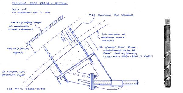
Figure 9. Design Development Sketch – showing grout infill and stud anchors and self-tapping threaded M20 stud-anchor
Durability, Design Life, and Maintenance
The permanent and variable loads applied to the PES appear small, and the spans short: on the platform elevation, the PES is required to support lighting, signage and other items of equipment, totalling no more than 1 kN/m2 (i.e. a typical cladding load). Even the smoke plenum soffit, formed in precast concrete, is no more than 2.2 kN/m2 on plan.
As far as variable actions are concerned, crowd load is represented by a 3.0 kN/m line load. In addition, piston loads from the movement of trains result in significant pressure changes, but the largest pressure change associated with each train is an impulsive ‘valve shut-off’ phenomenon, when the PSDs shut and air ceases to flow from the platform to the under-platform extract. A typical piston load for each train movement is 0.8 kN/m2, with an additional worst-case piston load of 1.2 kN/m2, only occurring under exceptional circumstances of a damper malfunction elsewhere in the tunnel ventilation system.
The first structural issue arising from these loads is fatigue, critically the complete pressure reversal for each train movement. The central Crossrail stations are designed for up to 30 trains per hour, with future provision for 24-hour running. Over the 120-year design life, this amounts to over 24 million cycles.
The second issue is the ongoing inspection and maintenance regime. This is partly to check the condition of the steelwork and corrosion protection, but also to check against bolt-loosening under the combined effects of the reversing piston pressure and vibrations. All bolts in the PES are therefore secured with locking washers. In addition, all connections were designed with the bolts visible for operatives working on mobile platforms on the platform or track. No bolt heads were permitted to become ‘hidden parts’, obscured by other elements of structure or secondary fixtures. This requirement is clearly a step beyond what would normally be expected in building design, and necessitated the use of a 3D BIM model (Fig.10). Coupled with the fatigue considerations, the connection design was considerably more challenging than might be expected given the magnitude of the loads.

Figure 10. BIM model used to develop the Access and Maintenance Strategy
The corrosion protection system applied to the PES steelwork also needed to be a minimum-maintenance solution. The location of the PES means that any form of paint system requiring major maintenance during the design life would be impractical. A stainless steel structure was considered, but a design life study dictated that the PES should be designed for a ‘C3’ environment[3]. The design team specified a galvanised finish (typically 140 microns) which provides the necessary design life with significant cost benefits compared to stainless steel.
Electrical Isolation
An electric train has an elevated earth potential, relative to the surrounding environment. The basic principles of electric train traction rely on the return current from the overhead lines passing through the rails. Over the distances involved, the rails have significant electrical resistance, and the net result is that the earth voltage on a train is ‘floating’ relative to its surroundings. This increase in earth voltage can be in the order of 50V or more. This is of no concern when the train is moving and the passengers are separated from the surroundings. When the train stops, however, it is imperative that it is not possible to touch the train and any surrounding metallic infrastructure on a separate electrical earth.
The PES designers therefore had to ensure that the platform edge structure was electrically bonded to the adjacent rails and isolated from the surrounding station earthing system. (In each Crossrail Station, the electrical earthing system does also eventually connect up to the rails, but at a single point in each station. This is to ensure that there is no alternative path for traction currents through the station infrastructure.)

Figure 11. Summary of Earthing and Bonding Strategy, and the need for electrical isolation within the PES Frame
Consequently, there is a requirement to electrically isolate the PSD and the adjacent PES-posts from the remainder of the PES-frame above and the platform edge rebar below (Fig.11). The latter of these two was achieved by locally reinforcing the platform edge with non-conducting GFRP rebar. The former, however, presented an additional challenge. The PSDs and the PES-frame form a wall bounding the platform space. As such, they are subject to the Subsurface Station Regulations, which originated in response to the Kings Cross fire disaster in 1988. These regulations stipulate that any material used in the construction of a wall in a public place must be of limited combustibility, as defined by the UK Building Regulations, which equates to Class A2 as defined by BS EN 13505-1. The regulation states that, to meet this stringent combustibility requirement, no plastic or polymer-based material can be used. Even GFRP with a phenolic resin did not meet the criterion. Consequently, the team looked to the realms of engineering ceramics and glasses for a suitable isolator material and three materials were short-listed: Mica Glass, Ceramit-14 and Macor (Fig.12):
Mica Glass is a machinable glass composite, comprising flakes of Mica embedded in glass. The mica flakes inhibit crack propagation and make the composite behave as a tough material.
Ceramit-14 is formed by heat-treating a naturally occurring ceramic, Pyrophyllite. As a naturally occurring material, it is cheaper than fully synthetic machinable ceramics, but its mechanical properties are less predictable. Ceramit-14 was only available in cylindrical dowels.
Macor is a proprietary, fully synthetic machinable ceramic and is used for many high-performance mechanical components.
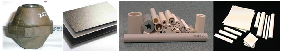
Figure 12. Proposed Materials for Electrical Isolators. L-R Mica Glass proprietary MM60-75; Mica Glass; Ceramit-14; Macor
These three materials were subject to a regime of design-stage mechanical testing at Imperial College, London. In specifying non-metallic components, C100’s designers were aware that these could not be expected to achieve the 120-year design life of the PES-Frame. Consequently, the steelwork around the isolators is designed with sufficient access to untighten, remove and replace the isolators in-situ. Furthermore, the steel bearing plates that ‘sandwich’ the isolators are widened to create a central zone to insert a flat jack, thus allowing the isolators to be unloaded during replacement, with minimal additional temporary works.
Testing
There are two elements of the PES frame that have been subject to preconstruction testing, under the supervision of the C100 team. These are the threaded, self-tapping concrete anchors, which fasten the PES frame onto the SCL and the electrical isolation blocks which allow the PES post to be bonded to a separate earthing system than the PES-frame above.
The first of these, the self-tapping concrete bolts, are classed as under-cut anchors in European technical guidance document, ETAG 001. As such, there is a prescribed series of tension and shear tests, along with a defined methodology for determining the design capacity.
The ETAG guidance requires tests in both cracked and uncracked concrete. In order to accurately replicate the conditions in the tunnels, the C100 testing specification included the construction of 2.4m x 1.2m SCL test panels. These were constructed offsite, using SCL applied to forms held vertically (Fig.13). The panels for cracked testing then had cracks induced by tensioning embedded rebar. Once the panels were cured and the cracks induced, they were transported to labs at Imperial College for testing.
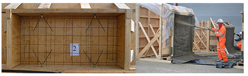
Figure 13. Spraying SCL test panels for threaded anchor testing
In addition to the prescribed tests, the C100 engineers specified additional single-bolt tests to investigate the behaviour of anchors that clash with rebar. In such instances, the bolts are installed in a diamond-cored hole, which is either pre-tapped or self-tapped to cut a thread into the end of the intersecting rebar. This series of tests enabled C100 to develop an optimum procedure for diamond-coring and tapping, which minimised the associated loss in design capacity of the anchor.
The structural designers were then keen to test the performance of the bolts in the complete connection assembly. Firstly, the team needed confidence that the anchors would perform satisfactorily under fatigue conditions and a complete connection assembly allowed the cyclic loads to a simulated. Secondly, the configuration of the connections, whereby the tolerances were taken up by a grout infill, requires the grout, SCL and anchors to act compositely to transfer shear. Consequently, the C100 test specification included the creation of prototype assemblies of SCL, grout, steel brackets and anchor bolts. To replicate the in-situ conditions as accurately as possible, the grout was poured and cured in the correct orientation, before being transferred to labs where cyclic loads were applied in a hydraulic test rig with the panels held horizontally (Fig.14).
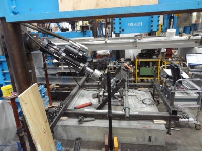
Figure 14. Testing of Stud Anchors in Bracket Assemblies
The second series of pre-construction testing concerned the electrical isolators. For the three proposed materials, published mechanical properties were available. The designers, however, needed to check the performance and robustness of the complete isolation assembly: the interface between the surrounding steel and the brittle isolators was a key concern.
A mock-up of the electrical isolation connection at the top of the PES post was fabricated (Fig.15). Into this assembly two alternative isolation configurations were inserted for cyclic load testing: The first used machined blocks of the isolation material, either Mica Glass or Macor. These machined bolts were bolted through with an M20 bolt, separated from the surrounding steel plate via an insulating top-hat bush – either in Mica Glass or Ceramit-14. The second configuration comprised proprietary stand-off Mica-Glass isolators, a double-tapered, moulded block of Mica Glass with a female threaded steel insert cast into each end.
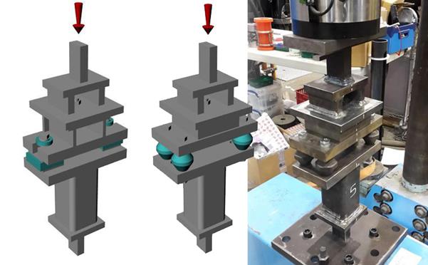
Figure 15. Connection Assembly used for electrical isolator testing
To simulate the action of the piston pressures, the connection assembly was subject to cyclic load tests, ranging from 10,000 cycles to 2,000,000 cycles per test. The loads were applied with a 5mm eccentricity to test the sensitivity of the assembly to erection tolerances.
The cyclic tests quickly revealed robustness issues with the Ceramit-14 when used in this configuration, with multiple fractures of the isolating bushes – both during assembly and the operation of the cyclic tests. There were also some instances of the Macor blocks fracturing where they were in bearing contact with steel plates.
Consequently, the alternative configuration, using proprietary stand-off isolators, was identified as the preferred option. This configuration exhibited no mechanical failures under the cyclic tests, and avoided the need for a flat bearing surface between ceramic and steel. This is also the simpler option, with just one, repeating component, rather than an assembly of bespoke, machined components.
Construction
The C100 design team prepared the PES-frame reference design for a generic, straight run of tunnel platform to RIBA Stage F1. As such, the station contractors were presented with an assured steelwork design, including full connection design, as well as precast planks for the plenum soffit with full reinforcement design. In this way, a common design approach undertaken by C100 created a major saving in design and coordination effort, compared to each contractor working up a PES design from a set of performance requirements.
Once the reference design was complete, the C100 designers were retained in a client-side technical support role, to explain the functional requirements of the PES, review contractors’ RIBA F2 information, and answer contractor queries. Across five stations there are four different main contractors, two of which used the same sub-contractor for the PES fabrication, demonstrating how the reference-design approach can create efficiencies in the supply chain. The site delivery of the PES frames across all five stations has taken place over three years.
In addition, the C100 technical support team helped the station contractors develop the site-specific end details of the PES, whilst ensuring the design intent and functional requirements of the reference design were preserved (Fig.16). The site-specific details ranged from simple end-terminations in a straight tunnel, through to more complex details resulting from tapered or curving tunnels at the platform ends. For example, at Tottenham Court Road station, the straight reference design is adapted for a curved platform and the geometry of the smoke extract plenum is widened into a basement-box at the western end.
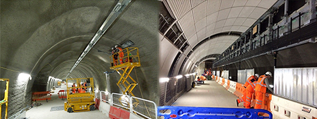
Figure 16. PES-frame under construction
Given the level of design development in the reference design, there was little significant variation in the contractors’ detailing of the primary PES structure. Some variation did, however, occur with regards to secondary steelwork and other fixtures and fittings on the PES, which were not redeveloped to RIBA F1 by C100.
One significant difference that did emerge between stations was the approach to the temporary support of the PES. The construction sequence dictated that a 1m unobstructed zone be maintained on the platform edge until track-laying was complete. The C100 reference design defined this requirement, and offered several options for addressing the temporary support. One station contractor elected to provide a cranked, propped support to the PES which transferred the weight of the PES onto the platform through a 1m offset. The remainder of the contractors locked the slotted hole connection at the top of the PES – either through additional locking bolts or bushes inserted into the slotted holes, to suspend the PES from the tunnel crown in the temporary condition.
Conclusions and Lessons Learnt
When the Elizabeth Line opens to the public, there will be a completely new sub-surface environment on the London Transport network. The 250m-long platforms with 5m unobstructed headroom will change passengers’ expectations of sub-surface rail, made possible by the gathering of lighting, signage, communications, and services distribution onto the vertical plane of the PES and the smoke-extract plenum concealed behind. It is unlikely that many passengers will give much thought to the structural engineering and complex interfaces, that make this elegant configuration possible. If the Crossrail platform becomes an exemplar for the design of sub-surface rail platforms in future, then the C100 design team will have more than fulfilled their objective.
The delivery of the PES design by the C100 Architectural Component Design package brought undoubted design efficiencies. Given the complexities of the interfaces with the tunnel lining, electrical isolation, coordination with the door locations, and offsite testing, the level of design supervision required would have been significantly greater, had these issues been tackled independently by the station teams.
From the structural engineer’s perspective, the PES design is intriguing. A cursory glance at the structural spans and the applied loads suggests that the PES is a simple element of secondary steel. Challenges have arisen, however, from the interfaces with other systems and are inherent in a heavily-serviced, spatially-constrained railway. The key to unlocking these challenges has been a structure with built-in flexibility; adaptable geometry allows the location of support posts to be varied, and adaptable load-paths allow the structure to be hung as well as propped. In this respect, the development of such ‘smart’ structural reference designs, with parameters that can be ‘flexed’ to suit local, temporary, or future conditions may become increasing common for large infrastructure projects in the 21st century.
Acknowledgements
Dr Sunday Popo-Ola, who oversaw the material testing of the isolator components and threaded anchors at Imperial College London, and led the subsequent analysis of the results.
References
[1] The benefits of the common-components approach on large-scale infrastructure projects are described in more detail in papers by McClements, N. ICE 2012 and Moxon, S; Atherton S. ICE 2012
[2] Coughlan, D, Diez, R, Comins, J and Stark, A, ICE 2016.
[3] Defined in BS EN ISO 12944-2
-
Authors

Julian Birbeck CEng MIStructE - Atkins
Julian joined the Crossrail project in 2013 as structural engineer for design, client advice and technical support services to Crossrail’s Chief Engineer’s Group (CEG) on the linewide design programme. The role involved engineering design, review and specification of station architectural components included tunnel cladding, passenger way-finding and trackside signage.
He worked as lead structural engineer for the Platform Edge Screen, including design, offsite testing and technical support to CEG in their acceptance of contractor designs, procured, developed and delivered at five stations in central London.
Julian is a chartered structural engineer with over 23 years’ experience on a broad range of landmark architectural and infrastructure projects.

Rosemary Smiley MEng - Atkins
Between 2014 and 2018, Rosemary was a structural engineer for the Crossrail route-wide common components package, C100, involved in the design, material testing, and construction support for the Platform Edge Screens for the five central mined stations. Rosemary is an engineer at Atkins, a member of the SNC-Lavalin group.

George Stowell BA(Hons) Dipl Arch MA(Dist) MRIAI RIBA - Atkins
For the Crossrail project, George was technical lead for the Canary Wharf Crossrail station over site development during 2012. Between 2013 and 2018, he was contract manager and client adviser for the line wide design team, comprising Atkins, Grimshaw, Maynard and GIA Equation. In the latter role for Crossrail Chief Engineer’s Group (CEG), Head of Architecture, the team undertook the following:
- Developed user and maintainer performance requirements through prototyping and testing.
- Assured the central London sub-surface station designs and line wide architectural components.
- Used assurance evidence to advise CEG on acceptance of designs provided by their station contractors.
George is an award winning Chartered Architect and RIBA accredited Client Adviser with over 26 years professional experience on the planning, design and delivery of high quality major public projects.

Ed Newman-Sanders CEng MICE - Atkins
Ed Newman-Sanders has twenty-five years of experience in structural building and bridge engineering design and construction. Ed was the lead structural engineer for the Crossrail route-wide common components package, C100. His work predominantly comprised the structural design and material testing for the Platform Edge screens for the five central stations. Ed was also the lead structural engineer for Crossrail’s only above-ground station in the central section, Custom House.
Ed is a Technical Director at Atkins, a member of the SNC-Lavalin group.