Field measurement by fully grouted vibrating wire piezometers
Document
type: Technical Paper
Author:
Michael S P Wan BEng DIC MSc CEng MICE, Jamie R Standing BEng DIC MSc PhD CEng MICE, ICE Publishing
Publication
Date: 03/11/2014
-
Abstract
Subsurface instrumentation was installed at a field monitoring site in Hyde Park and bordering Bayswater Road for measuring the ground responses to Crossrail tunnelling near Lancaster Gate. Prior to the passage of the tunnel boring machines, pore water pressures were measured, both in the “greenfield” ground and the ground in the vicinity of existing London Underground running tunnels, by three multi-level vibrating-wire (MLVW) piezometers installed in boreholes fully backfilled with cement-bentonite grout. The pore water pressures in the “greenfield” ground were at the same time measured by conventional standpipe piezometers and four pushed-in pressure spade cells with built-in VW piezometers.
This paper investigates the performance of the MLVW piezometers by comparing the post-installation and steady-state pore water pressure measurements made using these devices with those from the other piezometer types. Results from falling head permeability tests in the standpipe piezometers are presented and discussed. The measurements indicate drainage of groundwater into the existing century-old segmental cast iron lined tunnels. This measured drainage effect is compared with predictions made using a simplified finite difference model. It is concluded that the MLVW piezometers performed well and provide an efficient means of measuring pore water pressures at several depths within one borehole.
-
Read the full document
Introduction
Research is being undertaken by Imperial College London to investigate the effects of tunnelling on existing tunnels in London Clay. The research opportunity arose with the Crossrail construction of underground twin-bore railway tunnels through central London where the new tunnels interface with existing networks of London Underground Limited (LUL) tunnels and other utility tunnels. The Crossrail western tunnel section involves construction of twin tunnels using 7.2m diameter earth-pressure-balance tunnel boring machines (TBMs) mostly in London Clay. Comprehensive field monitoring was performed at an instrumented site in Hyde Park to assess the effect of new tunnel construction on both the “greenfield” ground and the ground in the near vicinity of existing segmental cast iron lined tunnels. During the year prior to the passage of TBMs, baseline monitoring work on the installed instruments was carried out. Wan and Standing (2014) describe the instrumentation scheme which includes various types of borehole instruments such as rod extensometers, in-place inclinometers and piezometers.
Recent advances in vibrating-wire instrumentation technology have led to an increasing popular application of VW piezometers in geotechnical projects. Dunnicliff (2008) and Contreras et al (2008) report successful installation and monitoring of VW piezometers installed by the fully-grouted method at various sites around the world. The VW piezometers, being a diaphragm type, require only a very small amount of water flow into the sensor to operate, making it possible for them to be installed in a borehole fully grouted with cement-bentonite grout of a suitable permeability. The fully-grouted method has a major advantage in that the straightforward backfilling procedure allows multi-level vibrating wire (MLVW) piezometer sensors to be installed in one single borehole. That makes it possible to obtain a pore water pressure profile with depth at one borehole location, significantly reducing the number of boreholes required.
This current paper presents and discusses the post-installation and the subsequent baseline measurements from the different types of piezometers, demonstrating the successful performance of the MLVW piezometers installed in single boreholes using the fully-grouted method. The measurements also establish a steady-state pore water pressure profile at the site as a baseline reference to compare with the future piezometric response from the Crossrail tunnelling operations.
Instrumented site
The field research site is located near Victoria Gate, at the northwest corner of Hyde Park, where the Crossrail west-bound and east-bound tunnels pass beneath the LUL Central Line running tunnels just east of Lancaster Gate. The actual crossing is directly beneath Bayswater Road.
Instrumentation plan
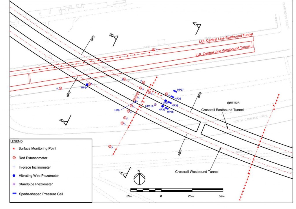
Figure 1 – Plan of instrumentation in Hyde Park and Bayswater Road.
A plan of the instrumentation layout is shown in Figure 1. There are in total 38 boreholes, each accommodating one or more instruments. Among other instruments, piezometers and spade-shaped pressure cells (or spade cells) have been installed around the Crossrail tunnel alignments to measure the pore pressure response resulting from the new tunnel construction. Within Hyde Park, the piezometers and spade cells were installed, as shown in Figure 2a, with the pressure sensors located at various distances vertically and horizontally around the east-bound tunnel to monitor changes in pore water pressure and total horizontal earth pressure as the TBMs approach and pass. There are two MLVW piezometer boreholes (HP32 and HP33) within Hyde Park, with six piezometer sensors at different depths in each borehole. A conventional standpipe piezometer (HP31A) was also installed at 6m away from one MLVW piezometer borehole to verify long-term pore water pressures measured by the VW piezometers. One spade cell (HP39) and three spade cells (HP35, HP36 and HP37) were installed at the level 1.5m above the tunnel crown and at the tunnel axis level respectively where the total horizontal earth pressures and pore water pressures are measured. There is one MLVW piezometer borehole (HP34), also containing six piezometer sensors at depths down to the Crossrail west-bound tunnel crown level, on the south pavement of Bayswater Road, being sunk at a distance of 5m from the LUL Central Line west-bound tunnel wall (Figure 2b).
Site geology and lithological units
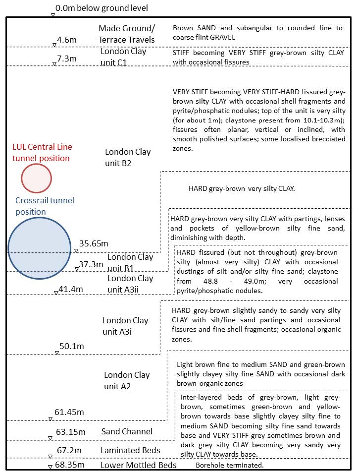
Hyde Park is in part of London Basin where marine sedimentation was affected by sea level changes, and has deposits from the London Clay Formation, Lambeth Group Formation and Thanet Sand Formation on the Chalk bedrock – a geology typically found in Central London. During instrument installation, a 68m deep borehole (HP6) was sunk by rotary core drilling through the whole thickness of London Clay Formation and the top few metres of the Lambeth Group Formation. Continuous triple tube core barrel samples were retrieved from the borehole and carefully preserved on site and transported to Imperial College for visual inspection and detailed logging. The lithological units of the London Clay Formation, as characterised by King, (1981), were identified by visual inspection and moisture content measurement (Standing and Burland, 2006).
In the instrumented site, the Chalk bedrock is believed to be at about 80m below ground level, overlain by a thin layer of Thanet Sand and about a 15m thickness of Lambeth Group deposits. At about 60m below ground level is the base of London Clay Formation which has an overall thickness of about 55m. There is a 3m thick layer of Terrace gravel above the London Clay, with a thin layer of made ground at the surface. Most of the 7.2m diameter Crossrail tunnel excavation is within the lower level of the London Clay unit B (B1 and B2), while about one metre of the base of the excavation (invert) is within the more permeable London Clay unit A3ii. The borehole instruments were positioned at different depths in the London Clay lithological units. Figure 3 shows the detailed soil descriptions of the ground determined from the borehole HP6. The boundaries of these lithological units are also shown in Figure 2.
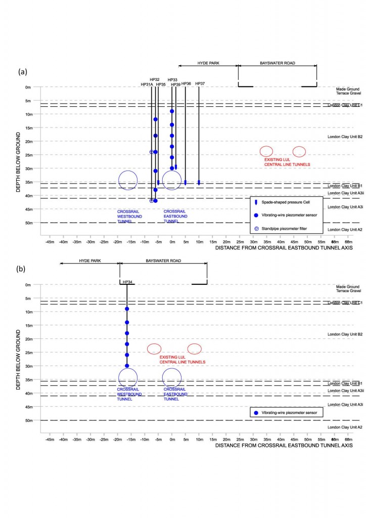 Figure 2 – Cross-section of piezometers (a) Cross-section A-A: piezometers in “greenfield” ground. (b) Cross-section B-B: piezometers in the vicinity of the existing LUL running tunnel.
Figure 3 – Detailed soil descriptions of the ground at the instrumented site.
Site hydrogeology
Two aquifers are present at the instrumented site, as reported by many authors (e.g. Simpson et al., 1989). The Terrace Gravels constitute the upper aquifer and the lower granular units of the Lambeth Group Formation and the Thanet Sand Formation the lower aquifer. These aquifers are separated by the London Clay Formation and, if any, the top clayey Lambeth Group Formation. During borehole drilling for installation of instrumentation, the upper water table was established to be about 4-5m below ground level. The deep water table was historically artesian but is now much lower due to excessive abstraction activities in early 1900s. Following the GARDIT strategy the water table is maintained below its natural level by controlled abstraction (Jones, 2007). As a result, the London Clay formation is under-drained, which is confirmed by the steady-state pore water pressure profile measured by the MLVW piezometers and the standpipe piezometer (See Section 6).
Piezometer types and installation
The pore water pressures in the ground near the Crossrail tunnel alignments are measured by three types of piezometer: (a) MLVW piezometers in fully grouted boreholes (HP32, HP33 and HP34), (b) VW piezometer sensors incorporated within spade cells (HP35, HP36, HP37 and HP39), and (c) a conventional standpipe piezometer (HP31A). These three types of piezometers are shown schematically in Figure 4. Table 1 shows the installation depths and the London Clay divisions where the instruments are positioned. All boreholes were formed by cable percussion drilling.
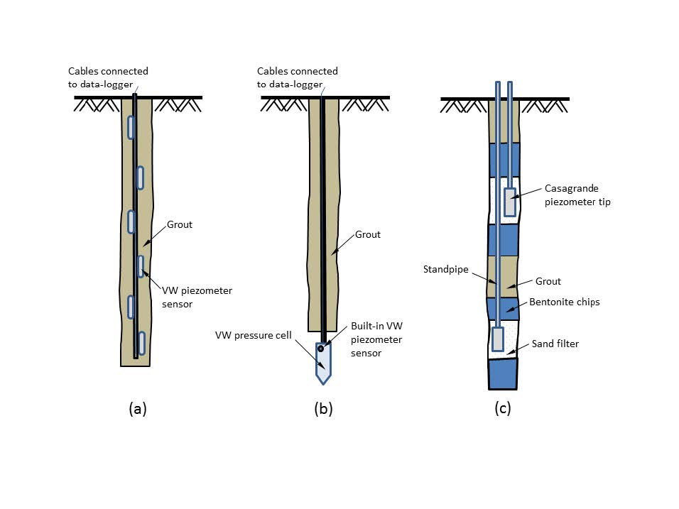 Figure 4 – Schematic presentation of three types of piezometers installed at the instrumented site: (a) Multi-level VW piezometers in fully grouted borehole; (b) VW piezometer sensor built in spade-shaped pressure cell; (c) Conventional standpipe piezometer.
Borehole Piezometer type Piezometer sensor/ response zone depth below ground level (m) London Clay unit Remarks HP32
(Hyde Park)
Multi-level VW piezometer 12.0 B2 18.0 B2 24.5 B2 Reading erratic after 3 months 31.0 B2 37.0 B1/A3ii 42.0 A3i HP33
(Hyde Park)
Multi-level VW piezometer 9.0 B2 14.0 B2 17.0 B2 22.0 B2 26.0 B2 29.5 B2 HP34
(Bayswater Road)
Multi-level VW piezometer 9.0 B2 14.0 B2 17.0 B2 22.0 B2 26.0 B2 Reading erratic after 3 months 29.0 B2 HP35
(Hyde Park)
Spade cell 34.0 B2/B1 HP36
(Hyde Park)
Spade cell 34.7 B2/B1 HP37
(Hyde Park)
Spade cell 34.6 B2/B1 HP39
(Hyde Park)
Spade cell 28.9 B2/B1 HP31A
(Hyde Park)
Standpipe piezometer 24.5 B2 37.0 B1/A3ii RT113R
(Hyde Park)
Standpipe piezometer 15.8 B2 Borehole installed by Crossrail’s contractor prior to current instrumentation fieldwork 47.0 A3i/A2 Table 1 – Details of piezometer installations at the Hyde Park site.
Multi-level VW piezometers
The VW piezometer is of the diaphragm type which requires only a very small amount of water flow into the piezometer to operate, eliminating the need for granular filters and meaning that the piezometer sensors can be fully backfilled by a low permeability grout. This has a major advantage in that the straightforward backfilling procedure allows multi-level piezometer sensors to be installed in one single borehole, thus making it possible to obtain a vertical pore water pressure profile at just one single borehole location, significantly reducing the number of boreholes required.
The installation was achieved by lowering the VW piezometer sensors into a borehole at pre-determined depths, before backfilling the borehole with a suitable cement-bentonite grout. The cables leading from the piezometer sensors were then connected to a data-logger housed within a headworks. The detailed installation method and selection and preparation of suitable cement-bentonite grout is described by Wan and Standing (2014). The backfill grout serves as a filter and also as a seal between piezometer sensors, prohibiting the vertical flow of water between the sensors within the borehole and allowing the pore water pressure at different depths to be measured independently.
Spade-shaped pressure cells
A spade cell consists of a pointed rectangular spade-shaped oil chamber, formed by two steel plates, connected to a VW pressure transducer. It measures total stresses acting on the pressure cell in the direction perpendicular to the spade surface. In-built at the top side of the spade is a porous filter which is connected to a second VW pressure transducer, so that the pore water pressure is also measured at the same time.
Each spade cell was installed by first drilling a borehole to a pre-determined depth (about 1m above the design instrument depth). The spade cell was then lowered into the borehole using hollow steel rods connected by couplers, until it reached the borehole base. The cables connected to the two VW transducers were fed through the middle of the steel rods and held at ground surface. The orientation of the spade was then adjusted so that the spade surface was facing perpendicular to the alignment of the Crossrail tunnel. A CPT rig was then mobilised to push the pressure cell vertically into the ground to the design depth (usually about 1m below the borehole base). Subsequently the steel rods were detached from the spade cell, and retrieved one by one, before the borehole was backfilled with cement-bentonite grout. The cables were connected to a data-logger housed within a headworks.
Unlike the multi-level piezometers, only one instrument can be installed within each borehole.
Standpipe piezometers
A two-level standpipe piezometer was installed by placing two conventional Casagrande type piezometer tips connected with PVC standpipes into two response zones at specified depths. The response zones were backfilled with sand to from granular filters 1m long which were sealed at the top and base by at least 1.5m thick layers of bentonite (installed using bentonite chips). The remaining length of the borehole is backfilled with cement grout.
About two months before the TBM arrival at the site, a pressure transducer was inserted into the base of each of the two 19mm diameter standpipes. Each of the transducers was connected via a cable to a data-logger housed within a headworks. This enabled the water pressure, and hence the water level in the standpipes, to be measured and recorded automatically. Manual measurements using a small dipmeter were also made from time to time, without the need of removing the transducers from the standpipes, to calibrate the automatically logged result. The cable connecting the transducers to the top of the borehole has a diameter of 7.5mm and occupies about 15% of the cross-section area of the 19mm standpipe. This was taken into account when interpreting the results of the falling head tests performed in the standpipe piezometers.
Falling head permeability test from standpipe piezometer
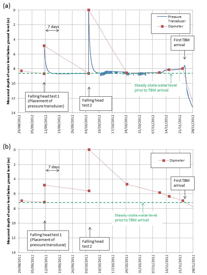
The pressure transducers were installed in the standpipe piezometer HP31A, with centre of the two response zones at 24m (London Clay unit B2) and 37m (London Clay unit B2/A3ii) below ground level, almost one year after the standpipe installation. By then the bentonite seals isolating the granular filters at the two response zones should be fully effective. A pressure transducer was also installed within a 47m deep standpipe (pieozometer tip near boundary between London Clay unit A3i and unit A2) RT113R constructed by Crossrail’s contractor prior to the current instrumentation fieldwork (it should be noted that this borehole is about 200m from the borehole HP6 used to compile Figure 3). Figure 5 shows the measured water levels in the standpipes in borehole HP31A for the 3 months leading up to the first TBM arrival. Before the transducer installation, the steady-state water levels in the 24m, 37m and 47m standpipes were measured to be 7.1m, 8.7m and 8.4m deep below ground surface respectively – an indication of slight under-drainage within the London Clay formation. The placement of the transducer assembly immediately displaced the water and led to a water level rise within the standpipe, before it dropped back to the original level. The process in itself can be treated as a falling head field permeability test. For the 37m standpipe in borehole HP31A, the excess water head took just about 3 days to dissipate, with the measured water level returning to its original value before the placement of the transducer (Figure 5a). On the other hand, the water level in the 24m standpipe dropped at a much slower rate, and did not return to the level before the transducer placement even after 3 weeks. It was later found that the transducer in the 24m standpipe was faulty and measuring erratic values and therefore only the dipmeter measurements are presented and used for data interpretation (Figure 5b). Three weeks after installation the transducers, the standpipes were topped up with water to ground level to perform another set of falling head permeability tests. The calculated permeability values from the falling head tests for both boreholes HP31A and RT113R are presented in Table 2. The coefficient of horizontal permeability was determined to be of the order of 10-9m/s for London Clay unit A3ii and unit A2, and 10-11m/s for London Clay unit B2. These values compare well with field test results from other sites in Central London and Heathrow (Standing and Burland, 2006; Hight et al, 2007).
Borehole Depth below ground level (m) London Clay unit Falling head test no. Coefficient of horizontal permeability (m/s) HP31A 24.0 B2 1 1.6 x 10⁻¹¹ 2 4.9 x 10⁻¹¹ 37.0 B1/A3ii 1 1.2 x 10⁻⁹ 2 1.2 x 10⁻⁹ RT113R 47.0 A3i/A2 1 2.5 x 10⁻⁹ 2 4.1 x 10⁻⁹ Table 2 – Results of falling head permeability tests in standpipe piezometer boreholes HP31A and RT113R.
Figure 5 – Measurements of water level in standpipes during the 3 months leading up to the first TBM arrival (a) 37m standpipe of borehole HP31A (b) 24m standpipe of borehole HP31A
Post-installation measurements from VW piezometers
During the instrument installation, negative excess pore water pressures were generated in the stiff clayey ground induced by stress relief and undrained shearing during the cable percussion borehole drilling. The magnitude of the excess pore water pressures depends on the existing ground stresses, the soil’s over-consolidation ratio, and degree of borehole support after drilling. Depending on the permeability (predominantly in the horizontal direction) of the ground and the spatial distribution of the initial excess pore water pressure, the excess pore water pressures at different depths would dissipate with time at different rates, until they balance with the far-field steady-state values.
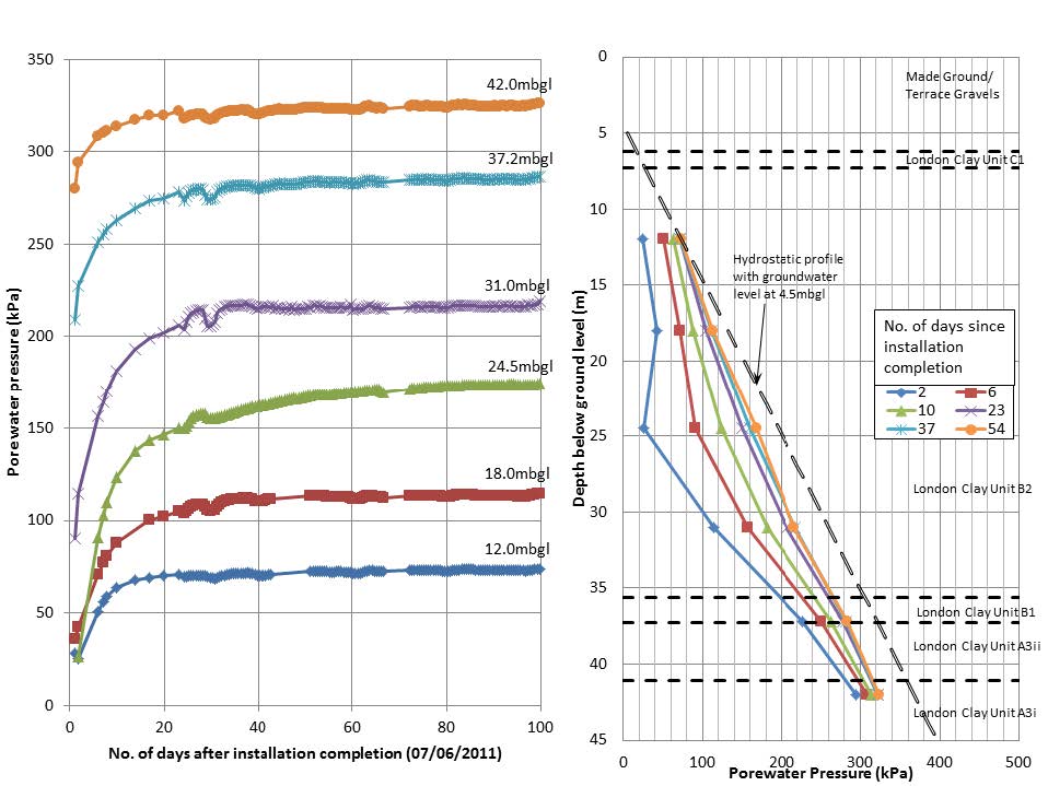
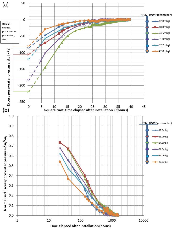
Initial measurements of the pore water pressure were started within the first few days after the installation of the VW piezometers in the fully grouted boreholes (HP32, HP33 and HP34). The initial measurements in borehole HP32 shows that the measured pore water pressures came to a steady-state within about 1 month (Figure 6).
Figure 6 – Post-installation measurement of VW piezometers in fully grouted borehole HP32.
The measured equilibration of pore water pressures can provide an indication of differences in the field permeability, at least qualitatively, of the soil at the respective depths of the piezometer sensors. For piezometer borehole HP32, the first readings were taken 24 hours after the installation was complete and therefore the initial pore water pressures immediately after the installation are not known and need to be determined. In order to obtain the initial excess pore water pressures, first the steady-state pore water pressures are assumed to correspond to the values at the end of the equilibration period. Then the measured excess pore water pressures are plotted against the square root of the time elapsed after the installation completion (Figure 7a). The initial excess pore water pressures for all piezometer sensors are obtained by extrapolating the early straight-line portions of the curves back to time equal to zero (broken lines in Figure 7a).It is then possible to normalise the measured excess pore water pressures with the corresponding initial excess pore water pressures and to plot the normalised values against logarithm of time (Figure 7b). By comparing the time for 50% dissipation (i.e. t50), for example, of total excess pore water pressures for different sensors, the coefficients of horizontal consolidation (ch) for the soils at respective piezometer depths can be ranked. In fact, if the initial spatial distribution of the initial excess pore water pressure is accurately estimated (e.g. by analytical solutions for a cavity contraction problem), the exact ch values can be determined from the t50 values using Terzaghi’s 1-D consolidation theory, assuming all ground water flow is horizontal and radial to or from the borehole wall.
The t50 values determined from Figure 7 are tabulated in Table 3, and suggest that the ground within London Clay unit A3i (42m below ground level) and B1/A3ii (37mbgl) has a higher coefficient of horizontal consolidation than the shallower ground within London Clay unit B2 (24mbgl and 18mbgl). This agrees with the trend observed from the results of the falling head permeability tests performed in the nearby standpipe piezometer (HP31A).
The observation that different magnitudes and rates of dissipation of the initial negative excess pressures were measured at different depths within the boreholes indicates that the cement-bentonite grout backfill formed a good seal between the piezometer sensors, otherwise similar magnitudes and dissipation rates of negative excess pressure would have been expected.
Depth below ground level (m) London Clay unit t50 (hours) 12.0 B2 50 18.0 B2 89 24.5 B2 80 31.0 B2 51 37.2 A3ii 32 42.0 A3i 23 Table 3 – t50 values determined from initial excess pore water pressure dissipation curves in borehole HP32.
Figure 7 – Dissipation of initial excess pore water pressures in different depths of VW piezometer sensors after installation. (a) Determination of initial excess pore water pressures immediately after installation; (b) Normalised excess pore water pressure dissipation with time.
Steady-state pore water pressures
One of the main aims of the piezometer instrumentation is to establish the steady-state pore water pressure profile prior to any tunnel construction work beneath the site. This would be used to verify the input to the numerical model for simulating the tunnel excavation at the instrumented site. The profile is also used as a reference baseline for determining the subsequent changes induced by the TBM passages. Two profiles of steady-state pore water pressure were established at the site, one in the “greenfield” ground (Figure 2a) and the other in the near vicinity to the existing LUL running tunnels (Figure 2b).
“Greenfield” ground
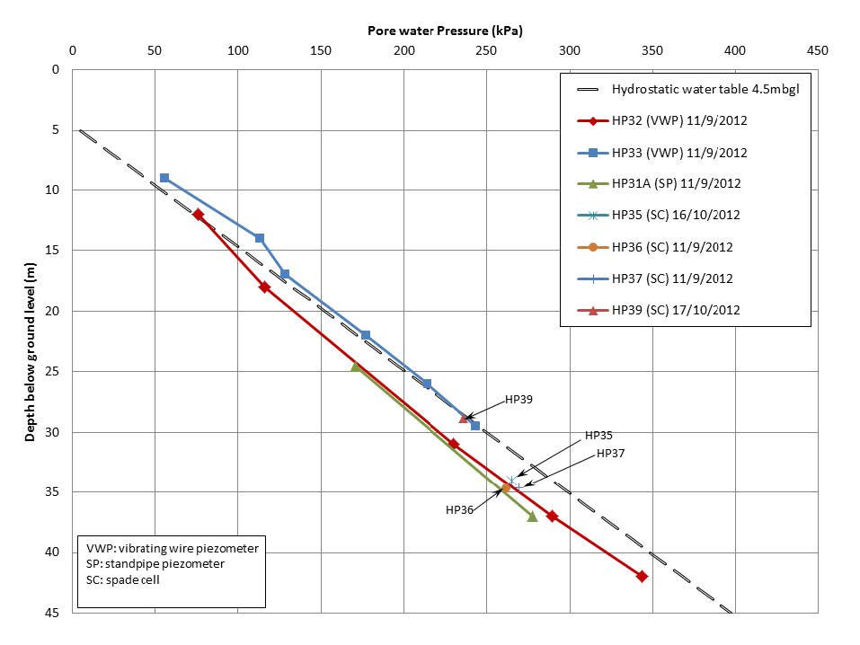
The steady-state pore water pressures measured by the MLVW piezometers (HP32 and HP33) about two months before the first TBM arrival are plotted against depth in Figure 8. The measured pore water pressures at HP33 are almost consistently about 20kPa higher at all depths than those at HP32, despite the two piezometer boreholes being only 5m apart. This could be due to the error associated with translating the measured voltages from the VW transducers to pressure values through calibration factors. Nevertheless, both show the same trend that the increase of pressure with depth is smaller than a hydrostatic pressure profile, indicating the slight under-drainage of the London Clay formation. The near surface London Clay is influenced by the pore water pressure associated with the upper water table within the Terrace Gravels, whereas the deeper London Clay is under the influence of the lowered pore water pressure within the underlying deep aquifer.
In addition to performing falling head permeability tests, the other purpose of installing the standpipe piezometer near the VW piezometers is to provide an alternative manual measurement of the pore water pressure to confirm the steady-state measurements from the VW piezometers. Also plotted in Figure 8 are the steady-state pore water pressures measured at the two response zones of the piezometer borehole HP31A, which is 6m from HP32. These manual measurements coincide nicely with the profile measured by the VW piezometers in HP32, suggesting the profile measured from HP32, instead of HP33, is more likely to be the true steady-state pore water pressure profile in the site.
Figure 8 – Steady-state pore water pressures measured in “greenfield” ground by standpipe piezometer (HP31), VW piezometers (HP32 and HP33), and spade cells (HP35, HP36, HP37 and HP39).
Further steady-state pore water pressure measurements from the three spade cells (HP35, HP36 and HP37) also confirm the profile of HP32, although measurements from the remaining spade cell (HP39) agree more with the profile of HP33 (Figure 8).
Ground in the vicinity of existing cast iron lined tunnel
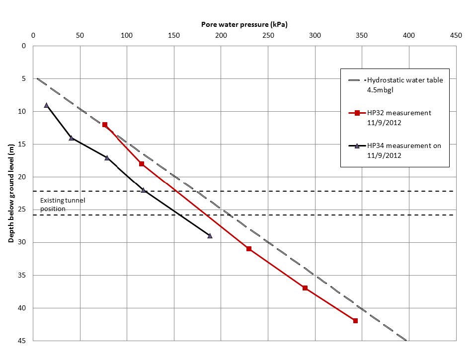
There is one MLVW piezometer borehole HP34 installed on the pavement of Bayswater Road, with a clearance of 5m from the wall of the LUL Central Line west-bound running tunnel. Figure 9 shows the steady-state pore water pressure profile measured by HP34. The “greenfield” profile of HP32 is also presented for comparison. It is observed that the steady-state pore water pressures measured in HP34 are 20kPa to 50kPa smaller than the “greenfield” values at corresponding depths, with the reduction larger at levels just above the LUL tunnel crown. It is believed that this deviation from the “greenfield” profile is related to the drainage effect of the segmental cast iron lined tunnel. While the shallower ground and the deeper ground are closer to and more quickly recharged by the upper and lower aquifers respectively, the groundwater around the depth of the existing tunnel is being drawn into the tunnel, creating a drop of the steady-state pore water pressure near the tunnel horizon.
Figure 9 – Steady-state pore water pressures measured in the vicinity of the existing LUL running tunnel by VW piezometers (HP34)
Gourvenec et al (2005) describes a similar piezometer instrumentation scheme in the vicinity of an existing tunnel, situated at 20m below ground level in London Clay, with the same type of segmental cast iron lining in Kennington. They found that the steady-state pore water pressure measured in the ground as close as 1.5m (smaller than one tunnel radius) to the existing tunnel is no different to the far-field value, suggesting that there is no or little drainage effect of the existing tunnel at that site. This is attributed to the fact that the existing tunnel in Kennington is near the base of the London Clay formation (unit A2) where the permeability is among the highest in the London Clay formation (generally the coefficient of permeability in unit A2 is in the order of 10-9 m/s). It is argued that the segmental lined tunnel there is relatively impermeable and therefore not providing a drainage path for the groundwater. This is not the case for the Hyde Park site, where the existing segmental lined tunnel is fully within the relatively low permeability London Clay unit B2. The results from the falling head permeability test in borehole HP31A indicate a coefficient of permeability of 10-11 m/s for unit B2. This implies that the segmental lined Central Line tunnel close to the Hyde Park monitoring site is relatively more permeable than the surrounding ground, thus draining groundwater and distorting the steady-state pore water pressure profile near the tunnel, as measured by the piezometers in HP34.
Finite difference approximation
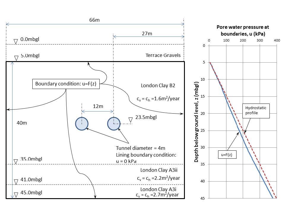
Figure 10 – 2-D finite difference model for simulation of drainage effect of existing segmental lined tunnels in London Clay
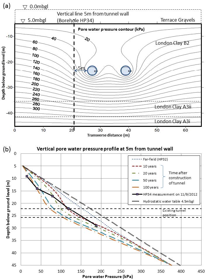
A simple 2-D finite difference analysis was performed to gain an insight into how the presence of the existing segmental lined tunnel affect the steady-state pore water pressure regime over a long period after the tunnel construction. Figure 10 shows the 2-D finite difference model with the boundary conditions shown. The 2-D mesh, with square elements sized 0.5m x 0.5m, extends from 5m below ground level (top of London Clay unit B2) to 45m below ground level (near the bottom of London Clay unit A3i) and is 66m wide with the existing tunnels at 23.5m below ground level. A far-field boundary condition of slightly under-drained pore water pressure profile as measured by the piezometers in HP32 is adopted along the four sides of the mesh. i.e. the top and bottom boundaries are constantly recharged by the shallow and deep aquifers respectively. The London Clay units were modelled as homogenous and isotropic with a coefficient of permeability of 5 x 10-11 m/s. However, the individual London Clay units were assigned different compressibility values. Depending on the relative permeability of the tunnel lining to the surrounding ground, the tunnel lining could be treated as a fully permeable drain, a fully impermeable boundary, or any state in between. For simplicity, the tunnel lining is modelled to be fully permeable and connected with atmospheric pressure (i.e. pore water pressure equals zero at all times). The finite difference formulations are based on the Terzaghi-Rendulic theory of consolidation. Consolidation was simulated for 100 years after the tunnel was constructed, as the length of the LUL Central Line tunnels beneath the site were built in the late 19th century.
Figure 11 – Results of finite difference analysis (a) Pore water pressure contours (kPa) at 100 years after tunnel construction; (b) Pore water pressure profiles along a vertical line 5m from the tunnel wall for after 10, 20, 50 and 100 years of consolidation.
The simulation results of the finite difference analysis are shown in Figure 11. The pore water pressures in the near proximity to the existing tunnel drop as consolidation over 100 years takes place, as can be seen from the pore water pressure contours around the existing tunnel (Figure 11a). The pore water pressure profiles for after 10, 20, 50 and 100 years of consolidation along a vertical line 5m from the tunnel wall are shown in Figure 11b. The largest reduction in pore water pressure occurs at the tunnel axis level. The steady-state pore water pressures measured from the VW piezometer borehole HP34 (5m from the tunnel wall) are shown in the same figure, and fall within the range of the simulated profiles. Although the simplified 2-D finite difference model has a number of approximations and limitations, the analysis results clearly demonstrate the probable drainage effect of an existing tunnel in relatively impermeable ground, corroborating the field measurements from the MLVW piezometers.
Summary and conclusions
Subsurface instrumentation was installed at a research site to monitor the ground response from the Crossrail tunnel construction. Three types of piezometers were used to measure the pore water pressure around the new tunnel alignment before, during and after the construction. It has been demonstrated that the MLVW piezometers installed in fully grouted boreholes perform well in measuring the steady-state pore water pressures. The results were confirmed by nearby measurements made using conventional standpipe piezometers and the VW piezometers built into spade cells.
The field permeability values for units within the London Clay Formation were determined from falling head permeability tests carried out using three standpipe piezometers. The soil permeability at other depths has been qualitatively compared using readings from the equilibration of excess pore water pressure during the initial measurements of the MLVW piezometers. It was found that the London Clay unit B2, which is a very stiff silty clay, has a coefficient of horizontal permeability of the order of 10-11m/s, whereas at the boundary between London Clay units B1 and A3ii, the latter being a hard clay characterised by the presence of fine sand partings and lenses, has a coefficient of horizontal permeability of the order of 10-9m/s.
Baseline steady-state pore water pressure profiles with depth have been established from the measurements of the MLVW piezometers in both the “greenfield” ground and the ground in near vicinity of the existing LUL segmental cast iron lined tunnel. The drainage effect of the existing tunnel, characterised by a reduction in the steady-state pore water pressure near the tunnel, is indicated from the MLVW piezometer measurements near the tunnel and has also been confirmed by a simplified finite difference model.
The MLVW piezometers at the site have been proved to perform well. Using this technique greatly reduces the number of boreholes needed if conventional standpipe piezometers are used, for which practically a maximum of two response zones can be installed in a borehole. The results from the baseline monitoring period provide confidence in the MLVW piezometers in fully grouted boreholes for the subsequent measurements during and after the passage of the TBMs.
References
Contreras, I. A., Grosser, A. T. & Ver Strate, R. H. (2008). Geotechnical Instrumentation News – The use of the fully-grouted method for piezometer installation, Part 1 and Part 2. Geotechnical News, (June), 30-37.
Dunnicliff, J. (2008). Geotechnical Instrumentation News – Discussion of “The use of the fully-grouted method for piezometer installation” by Contreras et al (2008). Geotechnical News, (June), 38-40.
Gourvenec, S. M., Mair, R. J., Bolton, M. D., Soga, K. (2005). Ground conditions around an old tunnel in London Clay. Proceedings of the Institution of Civil Engineers – Geotechnical Engineering 158, January 2005, 25-33.
Hight, D.W., Gasparre, A., Nishimura, S., Minh, N.A., Jardine, R.J. & Coop, M.R. (2007). Characteristics of the London Clay from the Terminal 5 site at Heathrow Airport. Géotechnique 57, No. 1, 3-18.
Jones, M. A. (2007). Rising Groundwater in Central London. Water and Sewerage Journal, 4, 35-36.
King C. (1981), The stratigraphy of the London Basin and associated deposits. Tertiary Research Special Paper, Vol. 6, Backhuys, Rotterdam.
Simpson, B., Blower, T., Craig, R.N. & Wilkinson B.R. (1989). The engineering implications of rising groundwater in the deep aquifer beneath London. Special Publication 69, CIRIA, London.
Standing, J. R. and Burland, J. B. (2006). Unexpected tunnelling volume losses in the Westminster area, London. Géotechnique 56, No. 1, 11-26.
Wan, M. S. P. and Standing, J. R. (2014). Lessons learnt from installation of field instrumentation to monitor ground response to tunnelling. Proceedings of the Institution of Civil Engineers – Geotechnical Engineering. (Revised manuscript accepted November 2013).
-
Authors
Michael S P Wan BEng DIC MSc CEng MICE - Crossrail Ltd
Geotechnical Engineer at Crossrail, Postgraduate Researcher at Imperial College London
Jamie R Standing BEng DIC MSc PhD CEng MICE - Imperial College London
Senior Lecturer, Imperial College London
-
Acknowledgements
Crossrail and Engineering and Physical Sciences Research Council (ESPRC), as major sponsors of the research project at Imperial College
Professors John Burland David Potts, Imperial College, for their contributions in discussing the choice and layout of the instrumentation
Mr John Dunnicluff, for his thoughtful review of the instrumentation plan
Royal Parks, London Underground Limited, Westminster Council, for the support provided during the installation work
