Geotechnical Risk Management for Sprayed Concrete Lining Tunnels in Farringdon Crossrail Station
Document
type: Technical Paper
Author:
Angelos Gakis Dr. Dipl-Ing, MSc DIC, CEng MICE, Petr Salak Eur Ing, MSc, CEng MICE, Adrian St.John, BEng (Hons) Eur Ing FICE CEng, ICE Publishing
Publication
Date: 03/11/2014
-
Read the full document
Project Overview
Crossrail is a new railway system which will provide, for the first time, a connection between the South-East and the South-West railway network through the centre of London. The Crossrail route will run from Maidenhead and Heathrow in the west through 21km of twin-bore tunnels under central London – connecting key London stations including Paddington, Bond Street, Tottenham Court Road, Farringdon, Liverpool Street, Whitechapel and Canary Wharf – and out to Shenfield and Abbey Wood in the east.
Crossrail will be integrated with the Tube and national rail networks and will include interchanges with nine London Underground lines. From 2018, Crossrail trains, each capable of carrying up to 1,500 people, will run at metro-style frequencies every two and a half minutes, in each direction, during peak periods. Farringdon station is situated at the heart of London’s rail network and will be one of London’s major rail interchange stations. Millions of people travelling to and through London will benefit from Farringdon station, which links Crossrail, Thameslink services and London Underground trains. It will also provide links to four of London’s airports ? Heathrow, Gatwick, City and Luton.
The station layout comprises two ticket halls, two platform tunnels, connecting cross passages, concourse tunnels, two escalator inclines, escape and ventilation adits. The chosen tunnelling system for Farringdon Station is sprayed concrete lining (SCL), which is a sequential open face tunnelling method. The primary sprayed concrete linings and cast in-situ/sprayed concrete secondary linings will be constructed using steel fibre reinforced shotcrete in combination with a sheet waterproofing membrane. In total, approximately 1,000 linear metres of SCL tunnels will be built with excavation cross-sections varying from 25m2 to 110m2 and will be constructed at depths of up to 35m below ground level. The use of compensation grouting is a key aspect of managing settlement caused by tunnelling works. The running tunnels between the stations are constructed by other Crossrail contractors using tunnel boring machines (TBMs).
Crossrail awarded the contract for the construction of the Farringdon Crossrail station to a joint venture of Bam Nuttall, Ferrovial Agroman and Kier (BFK) in 2011. BFK appointed Dr. Sauer & Partners (DSP) as specialist consultant responsible for all sprayed concrete lining (SCL) tunnelling works prior to ring closure. The Employer’s SCL designer (Mott MacDonald) was responsible for the design of the permanent works including the composite SCL tunnel linings post-ring closure.
Tunnelling Works
In general the SCL components at Farringdon Station comprised the eastbound and westbound platform tunnels, escalator inclines, lower concourse tunnels, cross passages, ventilation adits, stub tunnels and temporary connection tunnels (Figure 1). The platform tunnels were constructed using SCL methods to enlarge a 6.2m diameter precast concrete TBM pilot tunnel to the full platform tunnel size (circa 11.5m wide by 10.5m high).
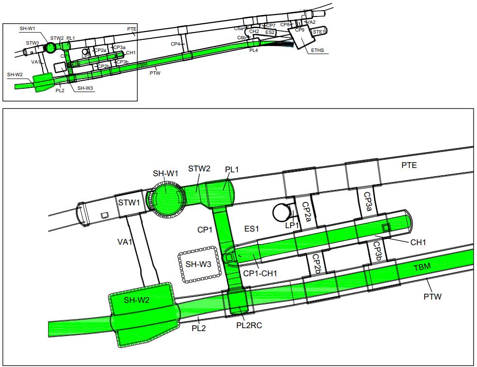
Figure 1 – Plan view of the tunnel structures in Farringdon Station, with a close up of the completed SCL works. Principal access for the SCL works was via shafts SH-W1 and SH-W2
The SCL structures at Farringdon Station completed by October 2013 were:
- Stub tunnel STW2 (enlargement from SCL pilot tunnel),
- Platform extension tunnel PL1 (enlargement from SCL pilot tunnel),
- Cross passage CP1,
- SCL soft eyes for TBM reception and transit,
- Lower concourse CH1 pilot tunnel,
- Temporary tunnels – PL2RC Wraparound and CP1-CH1 Connection. Westbound TBM segmental pilot tunnel completed.
Construction commenced with the breakout of the piles in shaft SH-W1 to create a soft eye for TBM reception, followed by breakout and construction on the opposite side for STW2 and PL1. PL1 was approximately 12m wide and 11m high, with a total excavation area of 110m2 . The next step was the breakout and construction of CP1 tunnel. At the end of CP1 temporary tunnel, a wraparound structure (PL2RC) was constructed to provide safe and rapid future access to the TBM segmental tunnel. In order to provide the construction team with additional programme flexibility and benefits, a temporary connection tunnel was designed and constructed between CP1 and CH1. This allowed the excavation of CH1 ahead of the construction of ES1, thus de-linking the SCL production from the works at SH-W3. In the SH-W2 shaft, two soft eyes were constructed to allow for the passage of the TBM. All of the SCL caverns constructed pre-TBM, were backfilled temporarily with foam concrete to facilitate rapid and safe transit of the TBMs without the need for temporary works or interrupting the TBM mining cycle. The tunnels constructed by October 2013 are highlighted in green colour in Figure 1.
Geotechnical Description
The typical London basin geological formations were encountered in the area of Farringdon Station. The upper strata comprised Made Ground, River Terrace Deposits (mainly in the Eastern part) overlying London Clay, the Lambeth Group, Thanet Sands and Chalk. The Harwich Formation beneath the London Clay was encountered in very few boreholes. An important feature was that the thickness of the London Clay layer was almost constant to the east of the Smithfield Fault (circa 20m to 22m thick), but was significantly thinner in the western part of the station (circa 4m to 15m thick).
The tunnels in Farringdon station were expected to encounter mainly the Lambeth Group formations (approximately 83%) and to a smaller extent London Clay (approximately 15%) and Thanet Sand (approximately 2%).
The main characteristics of the geology in Farringdon station were the following:
- the presence of multiple vertical / sub-vertical faults which affected the thickness, the elevation and the continuity of the soil layers.
- the thickness of the London Clay which varied between approximately 4m and 22m.
- the very low pore water pressures in the deep aquifer (Upnor Formation, Thanet Sand and Chalk) due to historical water abstraction. This had an under-draining effect (downward seepage and pressure relief) on the Lambeth Group pore water pressures (and partially on the London Clay), which were lower than hydrostatic from the water level at the top of the shallow aquifer.
- the spatial distribution of water bearing sand lenses within the top of the Lambeth Group (mainly Upper Mottled Beds), which varied in thickness and horizontal extent.
- the presence of the buried valley of the former course of the historical Fleet River in the area of the West Ticket Hall (along Farringdon Road). This resulted in a local deepening of the surface of the London Clay, an absence of River Terrace deposits and the localised presence of alluvium deposits (erosion effects).
The station can be separated geologically into two different sub-areas, west and east of the Smithfield fault (Figure 2). The main difference between these two areas was the thickness of the London Clay layer; this was affected by the multiple faults through this area and had a significant effect on the pore water pressure profile. Thus, in the eastern part of the station, where London Clay was significantly thicker, the pore pressures were increased in both this formation and in the Lambeth Group, hence, the under-draining effect from the deep aquifer was smaller than in the western part.

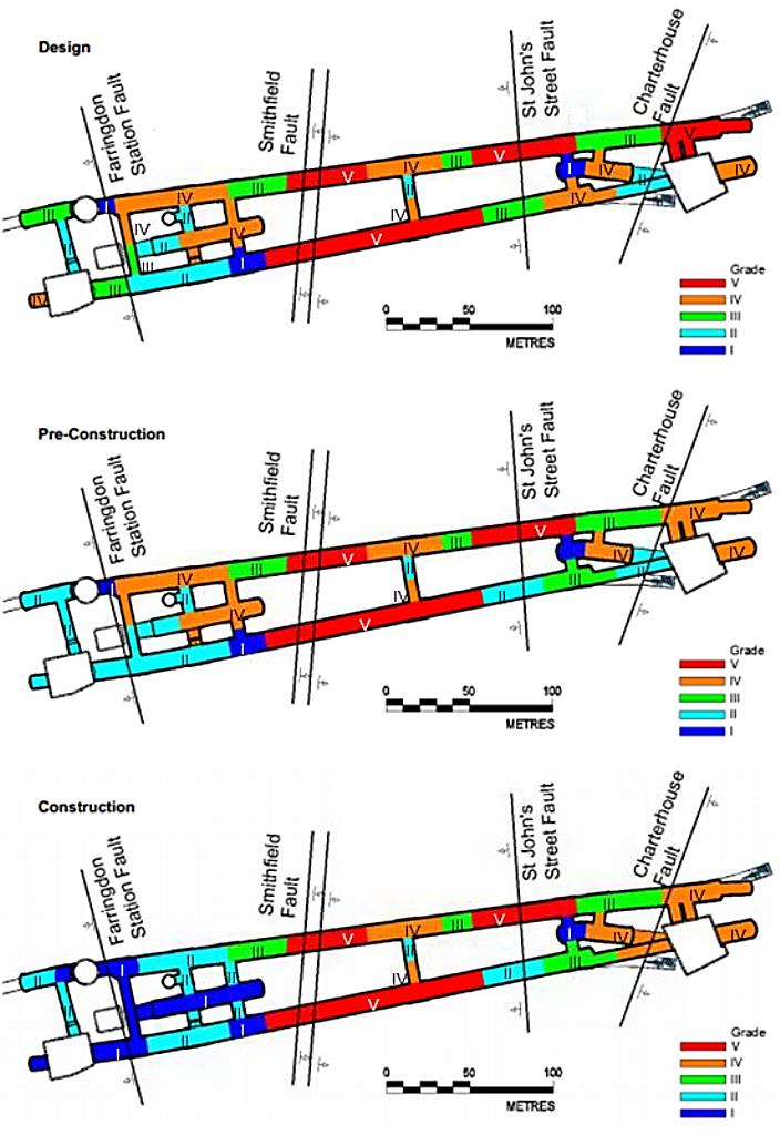
Figure 2 – Mapping of Geotechnical related Hazards in 3 phases of the project: Design, Pre-Construction and Construction
Two main aquifers could be distinguished; the upper aquifer located in the Made Ground and River Terrace deposits; and the lower aquifer comprising the lowest part of the Lower Mottled Beds, Upnor Formation, Thanet Sands and Chalk deposits. These two aquifers were separated by the London Clay aquitard. The pore water pressures in the deep aquifer were very low (almost zero) due to historical pumping and thus had an under-draining effect on the Lambeth Group deposits and partially on the London Clay. However, localised presence of sand bodies within the upper Lambeth Group was also expected and this was the feature that had the greatest potential impact on the stability and safety of the open face SCL tunnelling. After a thorough examination of the available data, DSP concluded that the most probable scenario was that these formations would be encountered as water bearing sand lenses rather than as continuous sand channels (i.e. without significant horizontal continuity).
Tunnelling and geotechnical risk assessment and mitigation in that challenging and variable geotechnical environment required a sophisticated and robust strategy to be in place.
Risk Management
Geotechnical risk management was a key aspect of successful delivery of this complex station in a complex urban environment surrounded by critical infrastructure and Third Party assets. Excavation stability, rapid ring closure and minimising settlement were the primary drivers for the site team, yet this had to be performed in some of the most challenging and complex geological conditions on the whole of Crossrail.
The risk management strategy adopted has been heavily influenced by published reports (see BTS & ABI (2003), HSE (1996) and ICE (1996)). The actual management and control of risks was delivered through the use of risk assessments and risk registers which originated from the Client’s permanent works designers (MMD). Their registers rigorously required to identify and clarify the ownership of risks and detailed clearly how these risks were to be allocated, controlled, mitigated and managed. The Risk Registers were ‘live’ documents which were reviewed on a regular basis and revised as appropriate. Where possible, these risks were eliminated at source through the design. The residual risks were transferred to the BFK, and were addressed in a variety of ways including; BFK methods and sequence of working; BFK construction management arrangements; temporary works design.
The CDM risk register provided by the client at Contract Award was updated by DSP to ensure that the design mitigation actions related to the actual design measures proposed by DSP, including implementation of depressurisation and toolbox items. The risk matrix scoring was reviewed to reflect the Contractor’s actual control measures and detail was added to the register to address the ground conditions detailed in the original design intent document provided by the permanent works designer (MMD).
At all times, the project team’s focus was on hazard identification and reducing risks as low as reasonably practicable (ALARP), and assigning those risk to the party most able to control them.
The CDM Risk Register demonstrated that the anticipated risks and hazards were identified and defined in a formalised risk management process and that the appropriate mitigation measures were in place and that the residual risks were ALARP. Communication of these residual risks was via the “SHE boxes” on the DSP temporary measures construction drawings; this highlighted to the BFK production team any unusual or unexpected risks associated with a location or activity which the team may not have reasonably anticipated. The residual risks were addressed through the risk assessments included in the BFK method statements and/or via the BFK “SCL Action Plan” and Emergency Preparedness Plans. Therefore, the design risks were ultimately addressed and mitigations briefed through the Task Briefing and Method Statements to the construction and supervisory staff and to the workforce.
The net effect of this process was a demonstrable chain of ownership of each of the identified risks, which showed how these risks had been eliminated or reduced ALARP by either the permanent works designer, the temporary works designer or the contractor.
Hazard Mapping
The primary hazard related to the SCL tunnelling works in Farringdon was the presence of non-cohesive, water bearing units in proximity to the excavated face. This hazard was mapped and presented in Figure 2 for three distinct stages:
- The design phase: dated April 2012 when the Optimised Contractor Involvement (OCI) period started with preliminary geotechnical investigation data being made available by the Client and MMD.
- The pre-construction phase: dated May 2013, when the excavation of the first tunnel (STW2) commenced, with additional ground investigation data becoming available. This additional information was obtained by BFK as a by-product of installing instrumentation and monitoring devices within 25 new boreholes around the station. This innovative idea provided the project team with a wealth of additional information to augment the existing ground model.
- The construction phase: dated October 2013, when part of the Early Western Tunnels was already constructed (the area in green on Figure 1)), with additional data acquired during the excavation of the tunnels.
The following assumptions were made in order to derive the presented mapping:
- Grade V [red] applied to either “low confidence” in the knowledge of the geological environment and/or evidence of water bearing sandy units in the tunnel horizon.
- Grade I [blue] applied to parts of the station that had already been excavated or thoroughly investigated, thus providing a high level of confidence.
- Larger tunnels posed a higher risk.
- The area east of Smithfield Fault was assigned an increased risk by default, as the pore water pressure regime was higher and tunnels were excavated within more risk-prone geological formations (the Upper Mottled Beds).
- Equally effective in tunnel investigation (probing) would be carried out for all the structures, reducing the risk by the same amount.
As illustrated in Figure 2, the geotechnical risk mapping has significantly changed through these three phases, with the area east of the Smithfield Fault exhibiting a higher residual risk compared to the west.
Geotechnical Risk Management
DSP developed an optimised geotechnical risk management framework which assessed all of the available data in order to minimise the residual risks at the tunnel face. In addition to the investigation already carried out from the surface, a pattern of in-tunnel probing was prescribed throughout the SCL works. In addition to the data acquired through probing, face mapping data was integrated into an existing 3D Geological model that was originally developed in 2009 by the British Geological Survey (BGS). This 3D model provided a useful day-to-day visual geological database, and allowed the site team to make accurate predictions for forthcoming SCL works. These tools and the way they were implemented are detailed below.
In-tunnel Probing
The in-tunnel investigation scheme, prescribed an optimized probing pattern ahead of the tunnel face. The implementation of this strategy was performed as follows:
- Investigation and depressurisation for “small” tunnels, such as pilot tunnels for STW1, STW2 and PL1, and CP1. This was performed ahead of the tunnel face from within the advancing face, by drilling inclined and horizontal probe holes and,
- Investigation of “enlarged” tunnels, such as STW1, STW2 and PL1 for the advancing enlargements by drilling radial probe holes within the previously installed pilot tunnels.Typical results from in-tunnel radial probing for PL1 tunnel are illustrated in Figure 3.
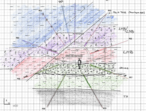
Figure 3 – In-tunnel radial probing results for PL1 tunnel, performed through the primary lining of the pilot tunnel, predicting the presence of the Farringdon Fault
DSP developed a flow chart to help to rapidly determine the future actions based upon the findings of the advance probing (Figure 4). This included criteria for water flow and pore-pressure control to incorporate individual or combined measures (in-tunnel water management, passive drains, or vacuum wells).
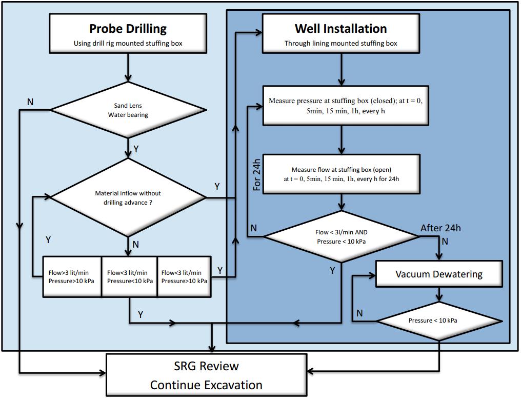
Figure 4 – Performance criteria for groundwater flow and pore-pressure control
For the early western tunnels, (comprising the soft-eyes for the TBM reception at shafts SH-W1 and SH-W2 and tunnels STW2, PL1 and CP1), this scheme started from the circular shaft SH-W1 initially targeting the Lambeth Group prior to the excavation of the pilot tunnels for STW1 and STW2 and PL1, as well as CP1 (the “small” tunnels). The in-tunnel investigation was completed successfully, without requiring any depressurisation measures to be implemented. In addition, the roof support measures that according to the base design had to be installed in several locations as the soil was expected to be of inferior strength due to the presence of faults, were de-scoped as the geological information determined that they were not required.
Tunnel Face Mapping
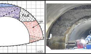
The open face excavation using SCL, allowed for accurate geological observations to be made and documented through the face mapping process. Face mapping was carried out for every single excavation step, and provided valuable, continuous data that confirmed the predictions made through the probing steps. This data was also presented in longitudinal geological sections. A typical representation of the geology encountered in the open face of PL1 tunnel, is presented in Figure 5.
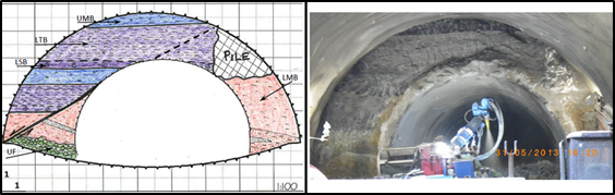
Figure 5. Face mapping of the excavated top heading of PL1 Enlargement, encountering a historical pile and Farringdon Fault
3D Geological Model
The 3D geological model for the area of Farringdon station was initially developed by the British Geological Society (BGS) in 2009, based on historical data and Crossrail specific site investigation. In 2013, the model was handed over to BFK/DSP and was integrated in the site supervision workflow. Initially, the additional data from borehole drilling and shaft excavation, received between 2009 and 2013 was used to update the model. Data from the face mapping has been progressively integrated into the model on a daily basis, thus providing a geological database for predictions of constantly increasing accuracy for future tunnels.
The cycle of risk reduction presented in Figure 6, started with the prediction based on the 3D geological model. After the excavation of each SCL tunnel, the data from the face mapping was integrated in the 3D model. Thus, the risk was reduced as the level of knowledge and confidence was constantly increasing. At the same time, in-tunnel probing provided additional data, validating at the same time the prediction from the 3D geological model.
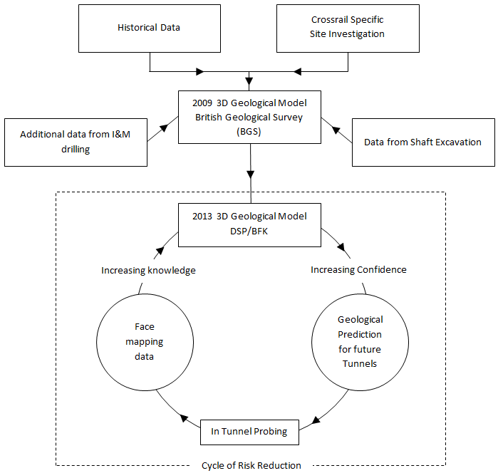
Figure 6 – Cycle of risk reduction through the implementation of geotechnical risk management tools
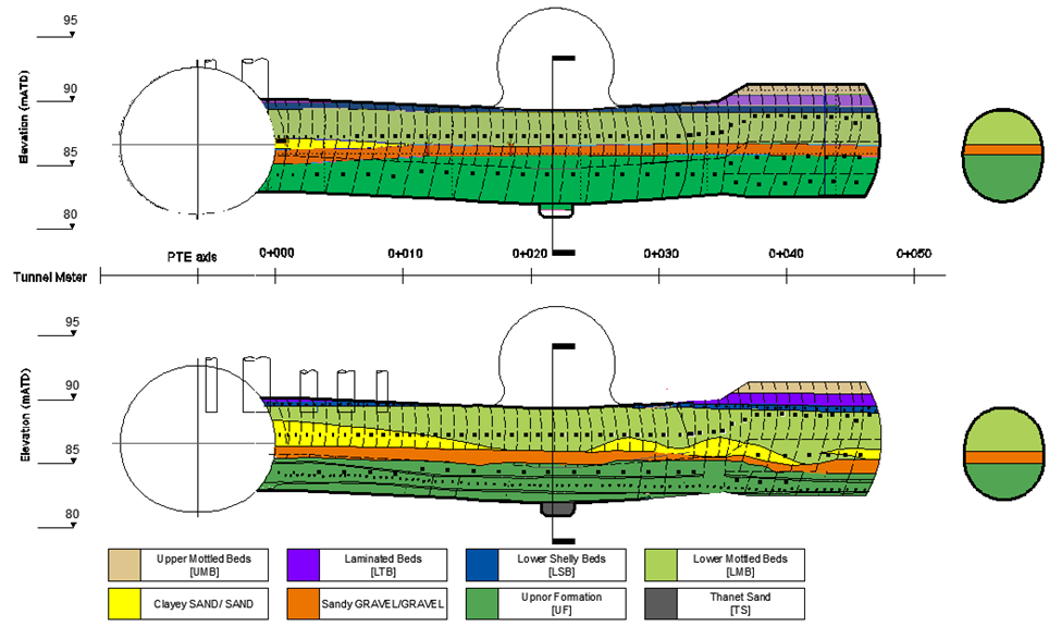
Figure 7 – Geological prediction prior to the start of excavation (top) vs. actual (bottom) longitudinal geological section for CP1. The 3D model provided a very good prediction in an area where very little borehole data was available.
Figure 7 presents a comparison of the predicted stratigraphy along CP1 from the 3D model, performed prior to the start of the excavation, against the ‘’real’’ stratigraphy as recorded through the face mapping process. This provided excellent correlation of results despite the fact that almost no investigation data previously existed in the area of the excavation of CP1.
Strategy for Implementation of Toolbox Items during SCL Tunnel Construction
The chosen tunnelling system for Farringdon Station was a sequential open face SCL tunnelling method that included:
- Prescribed mandatory measures, such as length of excavation steps, sprayed concrete lining thicknesses and in-tunnel probing which were required to be implemented in a prescribed sequence and were considered adequate for the “baseline” ground conditions, and
- Pre-defined contingency measures/toolbox items such as spiles or pocket excavation to be made available for use where localised adverse ground conditions were encountered.
This meant that an element of the design decision making and implementation had to be applied during the construction process. This decision making was managed through the “Shift Review Group” (SRG) and “Required Excavation Support” (RES) process. This ensured that all available relevant data was collated, reviewed and used to inform the next steps for safe tunnel advance, thus managing the risks within a well-defined and robust framework.
The BFK / DSP temporary measures design was built around a depressurisation scheme which included intensive prescriptive in-tunnel probing and pre-defined depressurisation measures ahead of the advancing tunnelling face. This design was supplemented by a set of pre-defined contingency measures/toolbox items which could be applied in the event of encountering localised unfavourable ground conditions. Toolbox Items included pocket excavation/face wedge, rebar spiling, grouted pipe spiling, pipe arches, additional probing and additional depressurisation.
The Senior SCL Engineer and Chief Geotechnical Engineer were employed by DSP and embedded into the BFK Engineering team, their remit being to oversee excavation stability at all times. If needed the toolbox items would be deployed at their discretion via the SRG and RES meeting; this included representatives from Crossrail, the SCL permanent works designer (MMD), the compensation grouting subcontractor, the asset protection engineer together with key members of the BFK and DSP engineering and supervisory teams. This process evaluated of all available date such as geotechnical data, 3D ground model, monitoring results, dewatering/depressurisation measures, compensation grouting data, and SCL early age strength results, etc, and formed the basis for safe advance of the SCL tunnels.
The output from the SRG was a signed RESS, which defined the advance, support, probing, depressurisation and toolbox requirements for the following shift. Five key signatories were required in order to validate the RESS, and no tunnelling was permitted without a valid RESS being displayed at the face. In the event of the RESS becoming invalid, a “Safe Stop Procedure” would need to be implemented.
Conclusions
The Crossrail Farringdon station is located in an area of variable and complex geology with a high degree of risk and uncertainty caused by the presence of multiple faults. Coupled with the presence of critical urban infrastructure and Third Party assets, it is arguably one of the most challenging SCL tunnelling projects on the whole of Crossrail.
The integrated delivery team of DSP and BFK have established a robust and comprehensive geotechnical risk management process to address these risks. This has yielded a greater understanding of the residual risks and enabled to provide a tailor-made pattern of probing and depressurisation measures consistent with the level of risk. Continuous improvements have also been achieved by feeding newly-acquired information into the 3D BGS ground model; this increased knowledge and confidence about the ground has enabled the project team to provide ever-improving predictions about the anticipated conditions.
DSP and BFK have developed an effective strategy for deploying toolbox items to react to adverse conditions encountered, within the wider structure of the SRG and RES process. This has required the full time site presence of DSP supervisory staff into key roles as “Senior SCL Engineer” and “Chief Geotechnical Engineer”, complying with onerous mandatory minimum competency requirements specified by CRL, embedded into the BFK organisation, thus enabling the highest possible standards of geotechnical risk management to be delivered on this project.
Acknowledgements
The authors would like to acknowledge the significant contribution from BFK joint venture, Crossrail and Dr Sauer and Partners for providing the necessary resources, guidance and support in the preparation of this paper. We would also like to thank the British Geological Survey that originally developed the 3D geological model of the Farringdon area in 2009 and handed it over to Dr Sauer & Partners in 2013 and especially Dr. Don Aldiss, for his valuable support and input during the development of the model.
References
BTS and ABI (2003) The Joint Code of Practice for Risk Management of Tunnel Works in the UK. London: British Tunnelling Society, 2003.
HSE (1996) Safety of New Austrian Tunnelling Method (NATM) Tunnels: A Review of Sprayed Concrete Lined Tunnels with Particular Reference to London Clay. Sudbury, Suffolk: HSE, 1996.
HSE (1996) The Collapse of NATM Tunnels at Heathrow Airport: A Report on the Investigation by the Health and Safety Executive into the Collapse of New Austrian Tunnelling Method (NATM) Tunnels at the Central Terminal Area of Heathrow Airport on 20/21 October 1994. Sudbury: HSE, 2000.
ICE (1996) Sprayed Concrete Linings (NATM) for Tunnels in Soft Ground. London: T. Telford, 1996. Print.
Glossary
BFK BAM Ferrovial Kier Joint Venture, main contractor
CRL Crossrail, the Client and Project Manager
DSP Dr. Sauer & Partners, specialist SCL designer for BFK
MMD Mott MacDonald, the Client’s permanent works SCL designer
RESS Required Excavation and Support Sheet
SHE Safety, Health and Environmental information
SCL Sprayed Concrete Lining
SRG Shift Review Group
TBM Tunnel Boring Machine
-
Authors

Angelos Gakis Dr. Dipl-Ing, MSc DIC, CEng MICE - Dr Sauer & Partners Ltd
Chief Geotechnical Engineer, Crossrail Farringdon Station
Petr Salak Eur Ing, MSc, CEng MICE - Dr Sauer & Partners Ltd
Design Manager, Dr. Sauer & Partners Ltd

Adrian St.John, BEng (Hons) Eur Ing FICE CEng - BAM Ferrovial Kier
Adrian St.John is a Fellow of the Institution of Civil Engineers and a Supervising Civil Engineer. He has spent most of his 24 year career working on major infrastructure and tunnelling projects in the UK and overseas, including the Brighton Stormwater tunnel and High Speed 1 at St Pancras. He spent 6 years as Chief Engineer for BFK Joint Venture who were the main contractor on Crossrail contracts C300, C410 and C435, and is the Design Director for Carillion Eiffage Kier (CEK) Joint Venture bidding for the forthcoming HS2 main civil works.