In Situ Stress Strain Measurements at Tottenham Court Road Platform Tunnel
Document
type: Technical Paper
Author:
Jessica Yu BE MSc DIC MICE, David Potts PhD DSc FREng CEng FICE FCGI, Jamie R Standing BEng DIC MSc PhD CEng MICE, Robert Vollum MSc PhD DIC CEng MIStructE, ICE Publishing
Publication
Date: 03/11/2014
-
Read the full document
Introduction
The redevelopment of Tottenham Court Road Underground Station started in 2011 as part of the Tube Upgrade Plan to improve and increase the capacity of the existing facility. The plan is to upgrade the station by 2016 to meet an estimated demand of more than 200,000 journeys per day once Crossrail is built.
During April to November 2011, major structural work was carried on the Northern Line platform tunnels as part of the station upgrade. This included removing tunnel lining segments on the platform side to allow construction of new cross passages to improve access to the platforms.
The works presented an opportunity for the Imperial College research team to trial their field instrumentation.
The main aims of the exercise were:
- To make discrete measurements of the strains in selected platform side segments before and after the segments are removed from the ring.
- To make continuous measurements of the opening and closing of circumferential and longitudinal joints on trackside segments which are left insitu and affected by adjacent excavations and tunnel segment removal.
Terminology
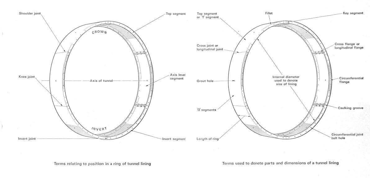
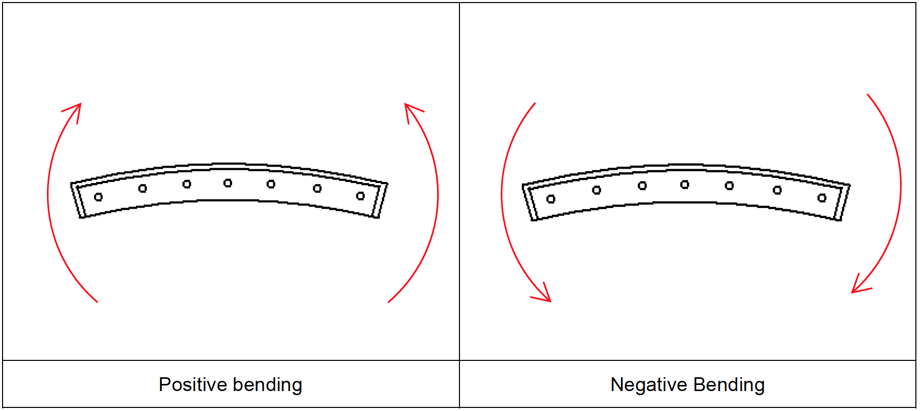
Figure 1 shows the terms relating to tunnel lining that are adopted in this report. Circumferential strain and longitudinal strains are defined as shown in Figure 2 . Positive bending refers to the mode of bending having a straightening effect on the segment, and negative bending increases the curvature of the segment (Figure 3).

Figure 1 Terms relating to tunnel lining (after Thomas, 1977)
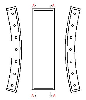
Figure 2 Directions of circumferential and longitudinal strains
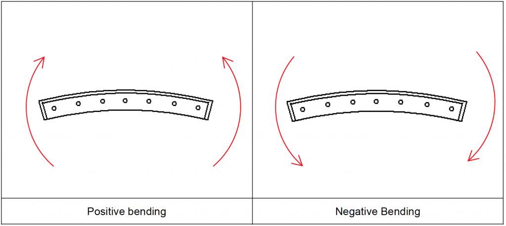
Figure 3 Positive bending and negative bending of a lining segment
The Instrumentation
DEMEC gauge
The DEMEC gauge is a portable device (Figure 4) which gives measurements of relative movement over a short gauge length. The studs were affixed to the surface of the structure using composite mortar. Once the studs were fixed and the mortar was set, the two points of the DEMEC gauge were carefully placed into the studs to take a zero reading. Further readings were taken subsequently to give the relative movement.
The selected gauge length was 150 mm. The gauge used was a digital gauge with a resolution of 0.001 mm. The accuracy under field conditions was given to be ±25 to 50 µε, compared to an accuracy of ±5 µε under ideal laboratory conditions (Dunnicliff, 1988).
Figure 4 DEMEC gauge
Electrical resistance strain gauges
350 Ω rosette type electrical resistance strain gauges with leadwires attached (Figure 5) were bonded directly onto the prepared cast iron surface using cyanoacrylate. Each strain gauge rosette was 16.5 mm by 20.3 mm in plan and less than 1 mm thick.
After the strain gauges were installed, an initial reading was taken with a portable, battery-powered datalogger, the P3 strain indicator (Figure 6).
A quarter-bridge network with three wires was used in strain monitoring. This, along with the higher resistance 350 Ω resistance gauges, was selected to reduce lead wire effects. The strains caused by temperature change at the gauge were corrected during data processing.
An AC excitation voltage was used for the portable strain indicator.
Temperature on the surface of the cast iron segments was measured with a laser thermometer probe to facilitate adjustment of strain gauge measurements.
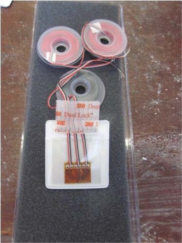
Figure 5 Rosette type electrical resistance strain gauge
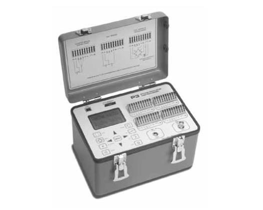
Figure 6 P3 Strain Indicator
Displacement transducers
LVDT (Linear Variable Differential Transformer) type displacement transducers were used to measure movement across the circumferential and longitudinal joints of trackside segments.
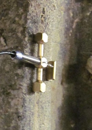
The displacement transducers were fixed onto the segments using a brass holder (Figure 7) which was initially positioned using magnets and then fixed in place using composite mortar.
The measurements were taken using mini-dataloggers. The mini-dataloggers were housed in a 120 mm x 120 mm x 90 mm ABS plastic box (Figure 8) which were fixed onto the skin of the trackside segments using composite mortar. There were two boxes in total, one box with two transducers set to log at 3 minutes intervals and the other box with two transducers set to log at 10 minutes intervals.
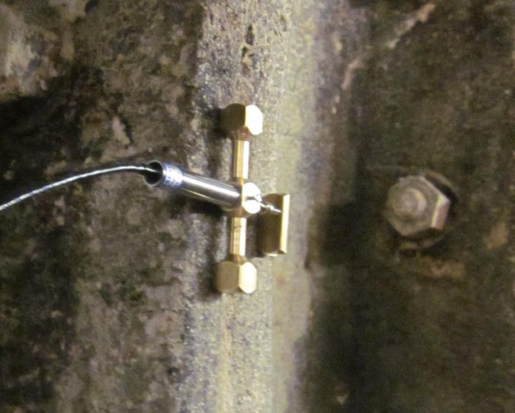
Figure 7 LVDT displacement transducer in metal holder

Figure 8 Dataloggers for LVDT and temperature gauge housed in plastic box
Temperature gauge
There was one temperature gauge with its own datalogger located in each plastic box (Figure 8).
The installation
Platform side installations
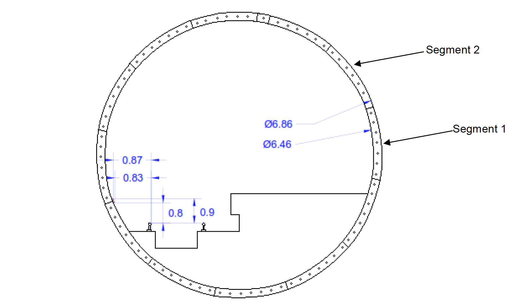
Mechanical and electrical resistance strain gauges were installed on the top and axis segments of one ring on the northbound Northern Line platform tunnel. The positions of the two segments and the approximate locations of the strain gauges are shown on Figure 9 and Figure 10.
Figure 11 and Figure 12 show the as-built installations. The protective coating seen in the figures consisted of a base layer of Teflon to insulate all bare connections, a layer of butyl rubber sealant, a layer of neoprene rubber and a top layer of aluminium foil tape.
On the inside of the circumferential flange, a pair of DEMEC studs was placed close to the intrados where the maximum strains are expected. Another pair of DEMEC studs was placed close to the skin to allow bending strains to be calculated.
Two pairs of DEMEC studs were located on the inside of the skin, to measure circumferential and longitudinal strains and allow comparison with the electrical strain gauge rosette.
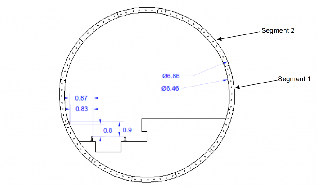
Figure 9. Northern Line northbound platform tunnel looking north
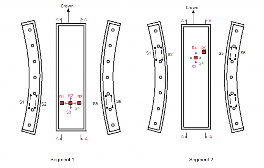
Figure 10. Approximate locations of strain gauges. (S=DEMEC span. R=strain gauge rosette)
Figure 11. Strain gauges on segment 1. Without protective coating (left) and with protective coating (right)
Figure 12. Strain gauges on segment 2.
Trackside installations
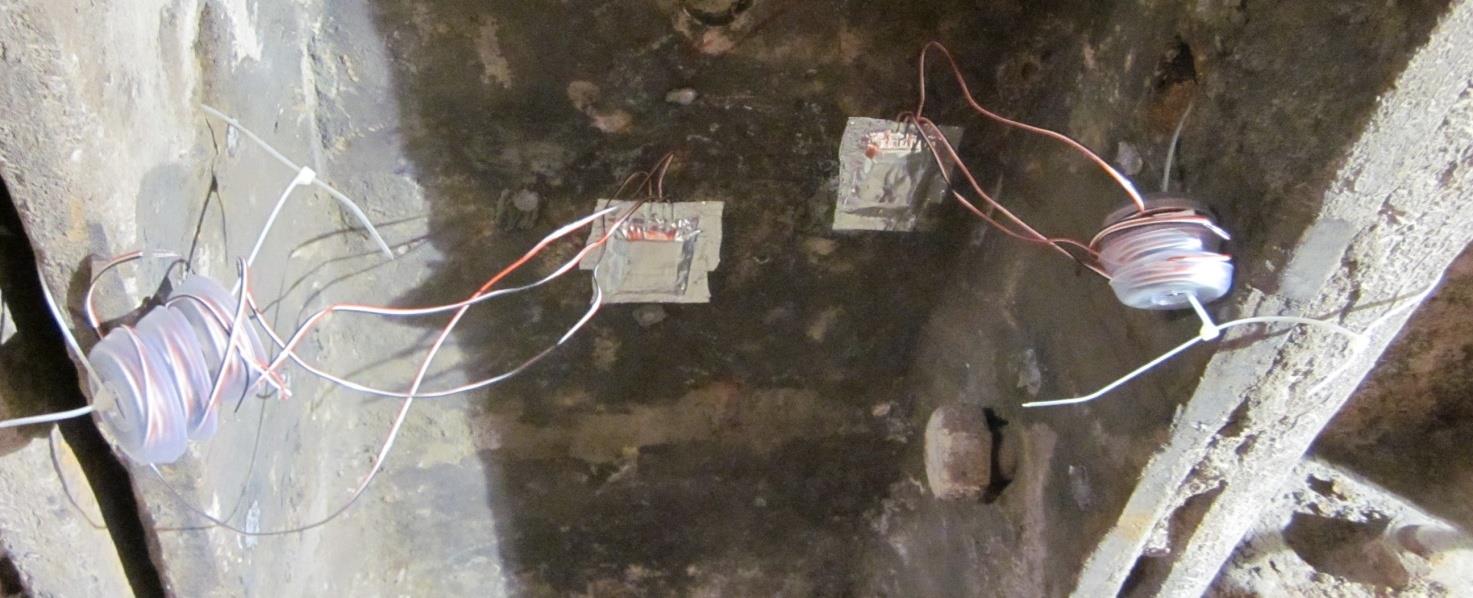
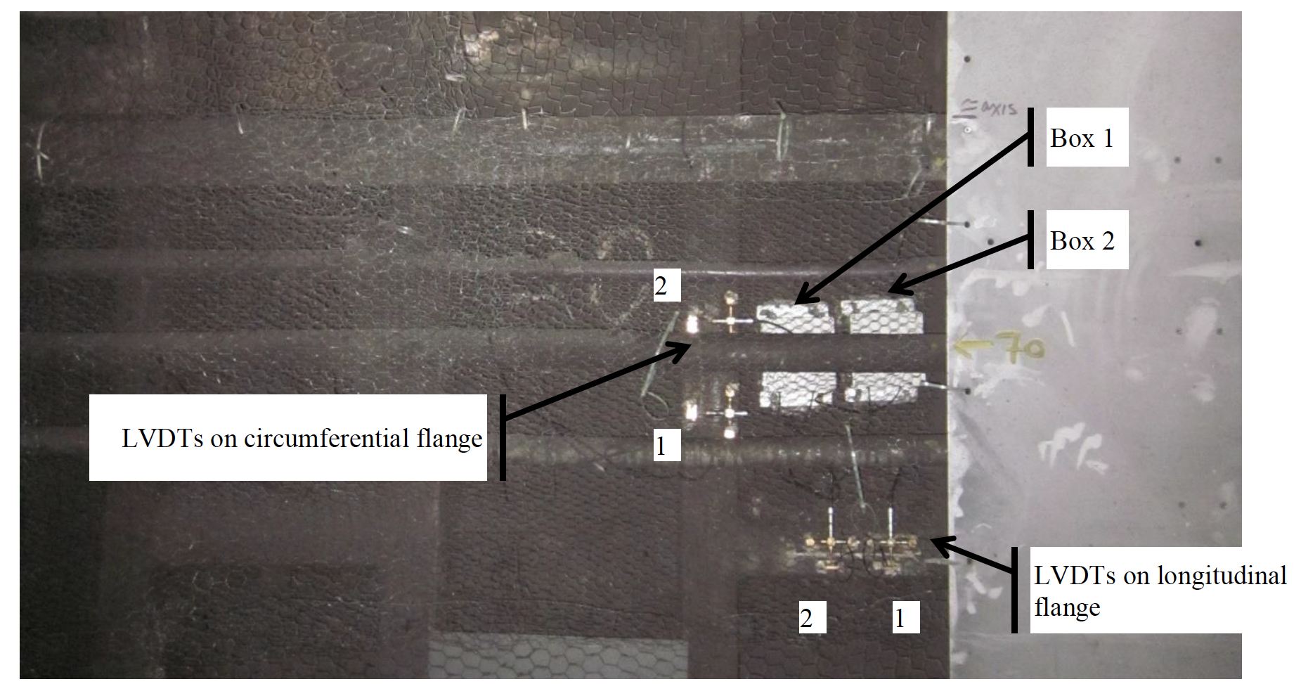
Figure 13 shows the location of the two data logging boxes on the trackside segment. Each box housed three data loggers, one for a temperature gauge and two for the LVDTs. One LVDT from each box was placed across the longitudinal joint and the other LVDT was placed across the circumferential joint.
The loggers in Box 1 were set to log every three minutes and the loggers in Box 2 were set to log every 10 minutes (refer to Figure 13).
Figure 13 As built photo showing locations of LVDTs and boxes housing loggers.
Estimation of unloading strain
It was assumed that when the platform tunnel segments were removed from the tunnel lining they were completely unloaded. The circumferential unloading strain assuming the full ground overburden was estimated to provide a comparison with the strains measured using the mechanical and electrical strain gauges.
The ground level was estimated to be at 25.0 m OD obtained from spot heights shown on drawing 1D0101-G0G00-G00-P-01016 Rev B from Geotechnical Sectional Interpretative Report 1&2: Royal Oak to Liverpool Street, Volume 3: Drawings, Report No. 1D0101-G0G00-00551 (GCG, 2009).
The tunnel axis for the LUL Northern Line platform tunnel was estimated to be at -5.0 m OD from drawing HAG-N105-8742-TUN-D-SEC-5-03426 by Halcrow for the Tottenham Court Road Station Upgrade project. The axis level coincided with the London Clay and Lambeth Group interface (Halcrow, 2008).
Information on the geometry of the lining segments was obtained from LUL Archive Drawing No. 146 for a 21’2½” (6.46 m) internal diameter tunnel. The section properties were calculated and used to estimate the tensile strain in the segment from the release of the hoop stress. The hoop load was estimated assuming 30.0 m of overburden. The resulting strain was calculated to be about 400 µε when the Young’s modulus was taken to be 100000 MPa for the grey cast iron.
Previous laboratory tests
Thomas (1977) investigated the structural behaviour of bolted ordinary grey cast iron (GCI) and spheroidal graphite iron (SGI) tunnel segments in the laboratory. The segments were dimensioned such that six GCI segments plus a key piece would join to form a ring of 3.83 m ID while 12 SGI segments plus a key piece would join to form a ring of 3.86 m ID. Since GCI behaves hysteretically upon loading while SGI exhibits little hysteresis, Thomas’ experiments were mostly performed on the SGI segments.
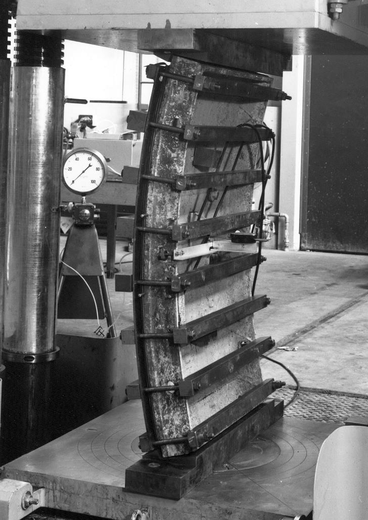
Figure 14 shows an SGI segment loaded at its quarter points. The loading was applied to the circumferential flanges and not onto the skin. The experimental investigation suggested that positive bending distorts the segment as shown in Figure 15. As the circumferential flanges straighten, the relatively flexible skin dishes radially outwards, which results in a distorted cross-section with the inside skin experiencing longitudinal compressive strain and the outside skin experiencing longitudinal tensile strain.
Thomas (1977) also investigated the effect of ground pressure on the bending characteristics of an SGI segment. A uniform pressure was applied to the back of a segment as shown in Figure 16. This pressure caused the skin to dish inwards and this dishing inwards of the skin induced longitudinal strains in the skin in the opposite manner to positive bending.
Figure 14. Bending test on SGI tunnel segment (Thomas, 1977)
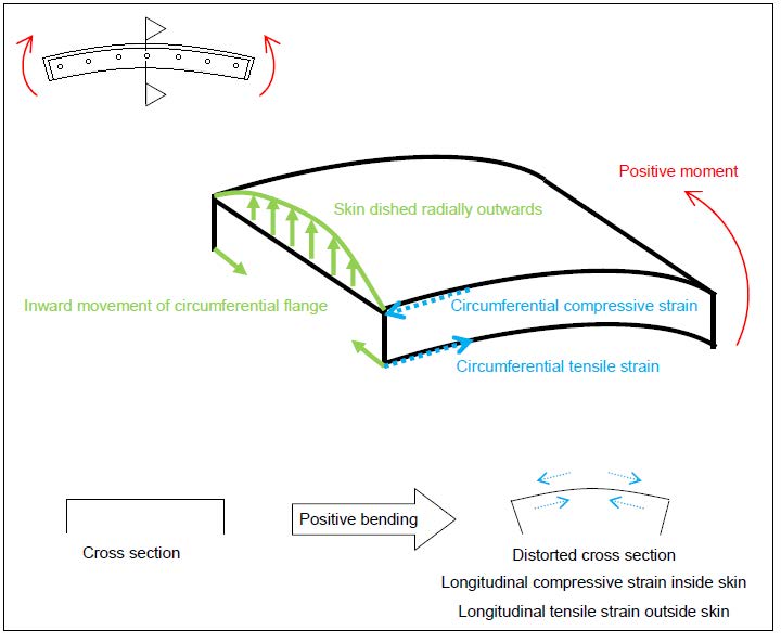
Figure 15. Schematic diagram showing distortion associated with positive bending (distortion is exaggerated)

Figure 16. Rubber bag strapped to the back of a SGI segment for the application of a uniformed pressure (Thomas, 1977)
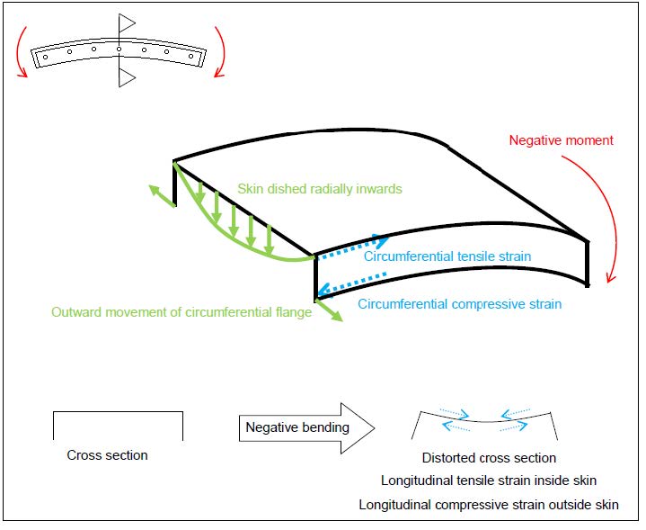
Figure 17. Schematic diagram showing distortion associated with negative bending (distortion is exaggerated)
Results from DEMEC measurements
Unloading strains due to removal of segments from ground
Using the baseline and post-segment-removal DEMEC measurements on spans 1, 2 and spans 5, 6 on the circumferential flanges (Figure 10), the axial and bending stresses due to unloading were estimated. In the calculations, the strain was assumed to vary linearly between spans 1 and 2 and spans 5 and 6. A constant modulus of 100 GPa was adopted. The results are presented in Table 1, along with the stress blocks, presented as variation in stress with distance away from the extrados, for each circumferential flange.
The measurements from all four circumferential flanges indicated circumferential tension and a positive bending moment upon unloading, which was expected since the segments would have experienced circumferential compression and negative bending moment (see Figure 17) while underground. It was not clear why the circumferential tension was higher on span 1-2 for both segments. However, the magnitude of circumferential tension from span 1-2 on both segments compared well with that calculated assuming full overburden unloading, which was estimated to be 940 kN.
On the inside of the skin, DEMEC span 3 measured tensile circumferential strains from unloading, and DEMEC span 4 measured compressive longitudinal strains, for both segments. Referring to Figure 15, these distortions could be associated with the dishing outwards of the skin related to positive bending. The ratio of the longitudinal strain to circumferential strain was 1.2 for segment 1 and 1.0 for segment 2. Given that grey cast iron has a Poisson’s ratio of approximate 0.26, this distortion of the skin was not due to Poisson’s effect.
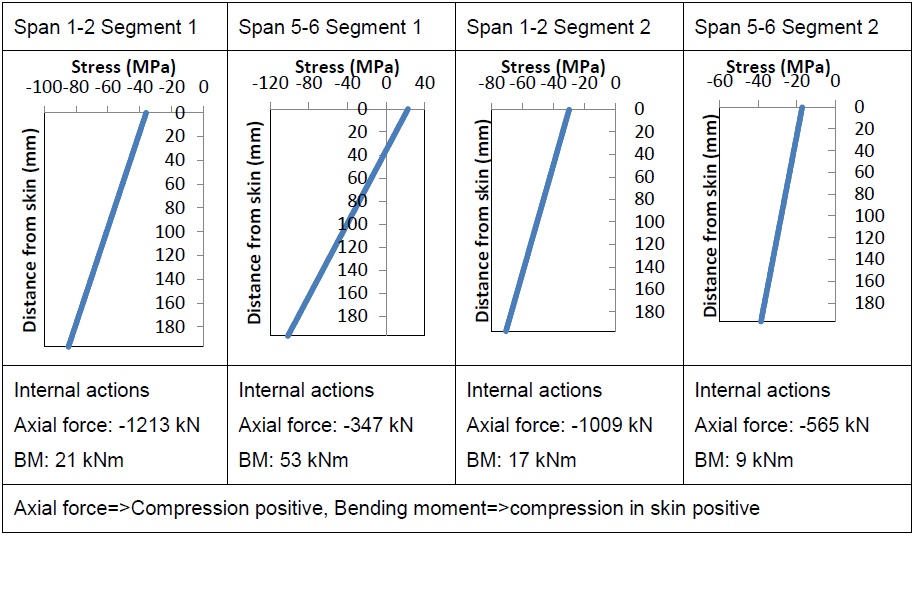
Table 1. DEMEC results for circumferential flanges
Intermediate DEMEC measurements
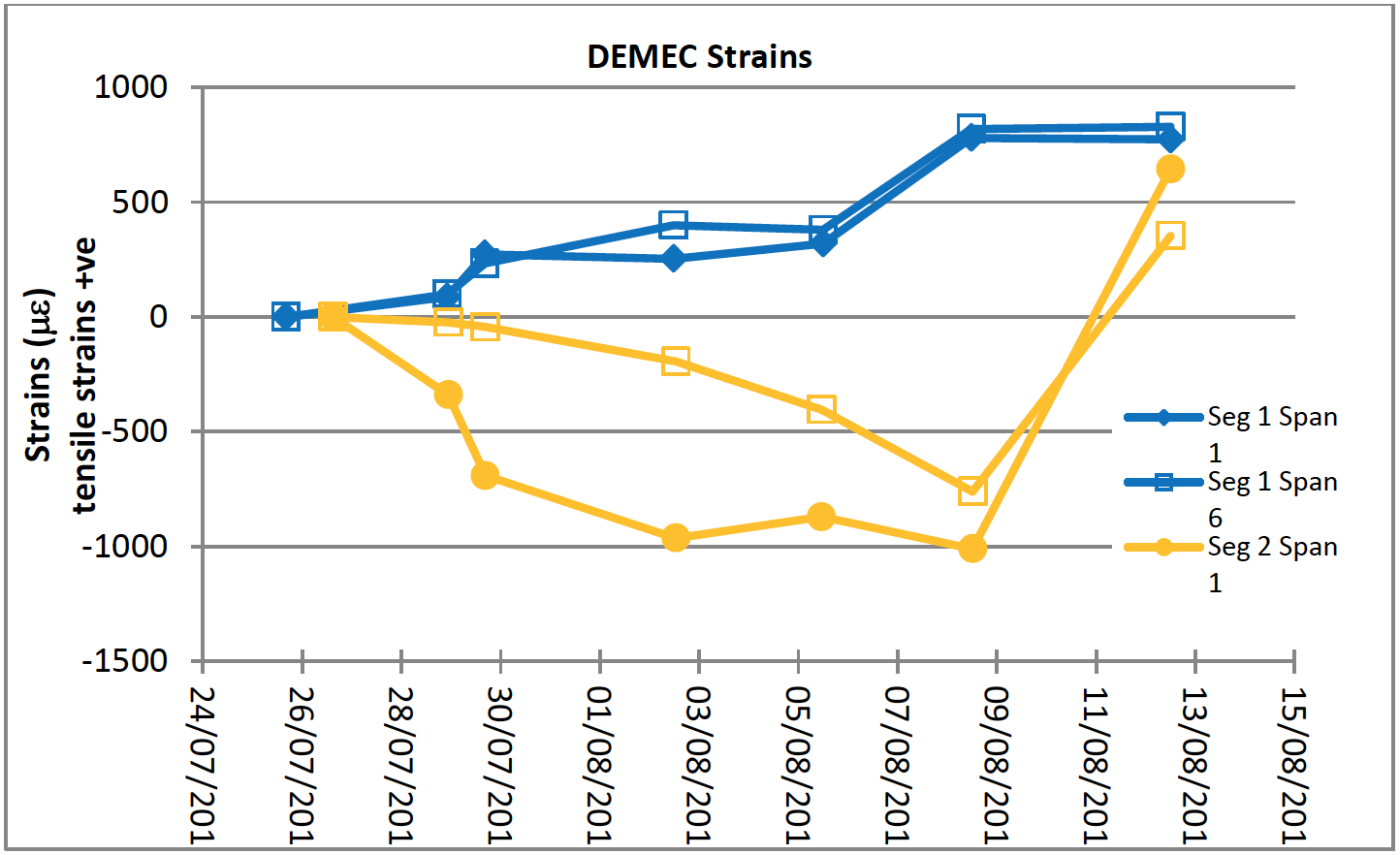
A wire bracket was attached onto the skin to protect strain gauge rosettes from mechanical damage (Figure 18). Due to the presence of the wire bracket, only DEMEC spans 1 and 6 (see Figure 10) were available for intermediate monitoring between day of installation and the day of segment removal. The results are given in Figure 19.
For segment 1, span 1 and 6 measured increasing tensile strain, which is in line with the segment experiencing positive moment as the excavation works around the segment releases the ground loading. However, for segment 2, span 1 and 6 measured increasing compressive strains during the excavations works around the segment, while the segment was still part of the lining ring.
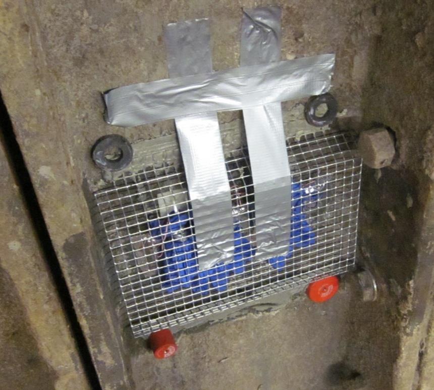
Figure 18. Wire bracket to protect strain gauge rosettes

Figure 19. Development of strains on the circumferential flange
Results from strain gauge rosettes
Unloading strains due to removal of segments from ground
Using the baseline and post-removal strain measurements from each strain gauge in a rosette, the principal major and minor direct strains and the orientation of the principal direct strain directions on the surface of the cast iron were calculated for each rosette location. The calculations included corrections for strain gauge thermal output and gauge factor variation with temperature.
Refer to Figure 10 for the locations of the rosettes. The results for segment 1 are presented in Table 2. The results for segment 2 are presented in Table 3. Each plot shows the direction and magnitude of the major and minor principal direct strains on the surface of the cast iron. The y-axis represents the circumferential direction and the x-axis represents the longitudinal direction as illustrated in Figure 2.
The strain gauges measured tensile strains in the sub-circumferential direction and compressive strains in the sub-longitudinal direction. This is consistent with measurements from DEMEC spans 3 and 4. The circumferential strain and longitudinal strain at the locations of rosette 2 and rosette 4 have been resolved from the major and minor principal direct strains to allow comparison with the DEMEC measurements. This is given in Table 4.
From Table 4, it can be seen that there was less than 5% difference in the circumferential unloading tensile strains measured using the electrical and mechanical strain gauges. However, the difference between the longitudinal strains measured by the two instruments differed greatly, well over 20%. This larger difference corroborates with the positive bending mode of distortion the segment was expected to experience upon unloading, with the skin dishing radially outwards, compressive strains was expected on the inside of the skin in the longitudinal direction. Since the DEMEC instrument had a longer gauge length compared with the rosette, the compressive strain measured by the DEMEC was also larger. In the circumferential direction, axial tensile strain dominated over bending strains, and the difference in gauge lengths had lesser effects on the measured strains.
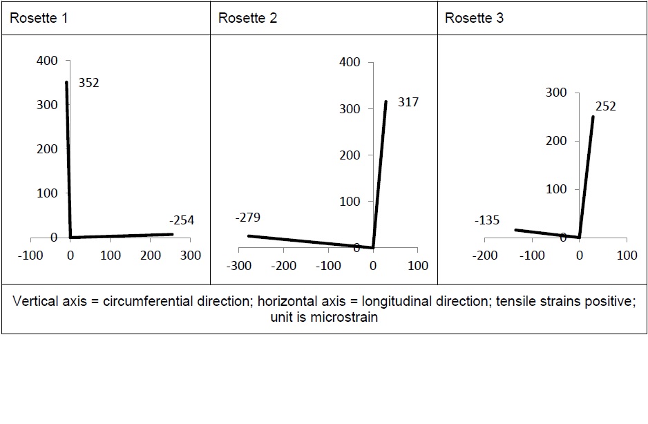
Table 2 Strain gauge results for segment 1
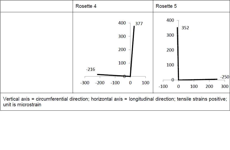
Table 3 Strain gauge results for segment 2
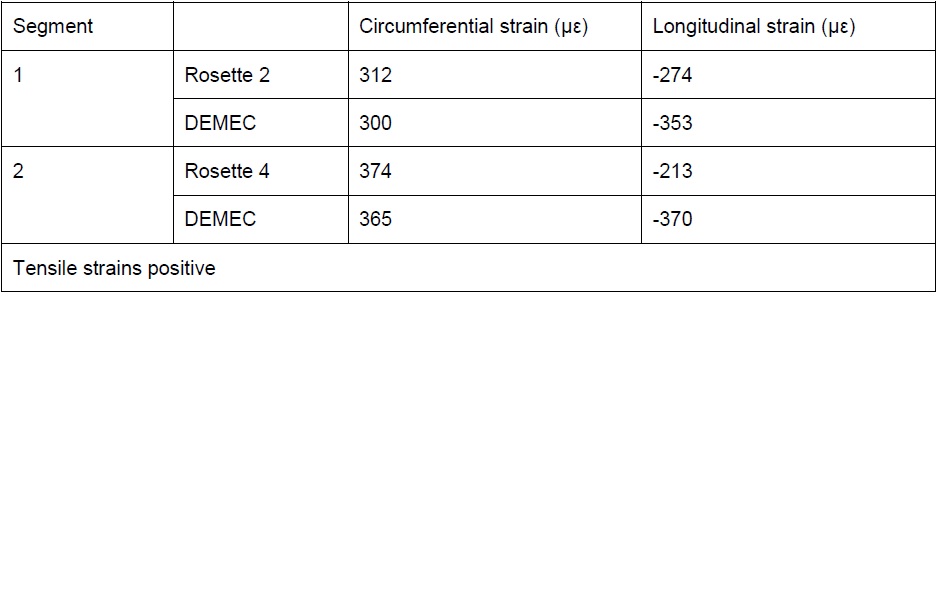
Table 4 Comparison of DEMEC and strain gauge rosette results
Intermediate strain gauge rosette measurements
The baseline readings and the last set of readings taken before segment removal were used to calculate the changes in principal major and minor strains in the skin. The intermediate DEMEC strains near the intrados of the circumferential flanges suggest that excavation works around the tunnel lining caused positive bending in segment 1 and negative bending in segment 2, before the segments were removed from the tunnel. The results for segment 1 are presented in Table 5. The results for segment 2 are presented in Table 6. The plots show the magnitude and direction of the principal major and minor direct strains on the surface of the cast iron. The strains in the circumferential and longitudinal directions have been calculated and are given in the tables.
For segment 1, the measured strains are predominantly slightly compressive in the longitudinal direction, and slightly tensile in the circumferential direction. The compressive strains in the longitudinal direction are consistent with the assumed mode of positive bending as suggested by the DEMEC readings on the circumferential flange.
For segment 2, the measured strains are tensile in the longitudinal direction, consistent with the negative mode of bending suggested by the DEMEC readings and the associated dishing inwards of the skin.
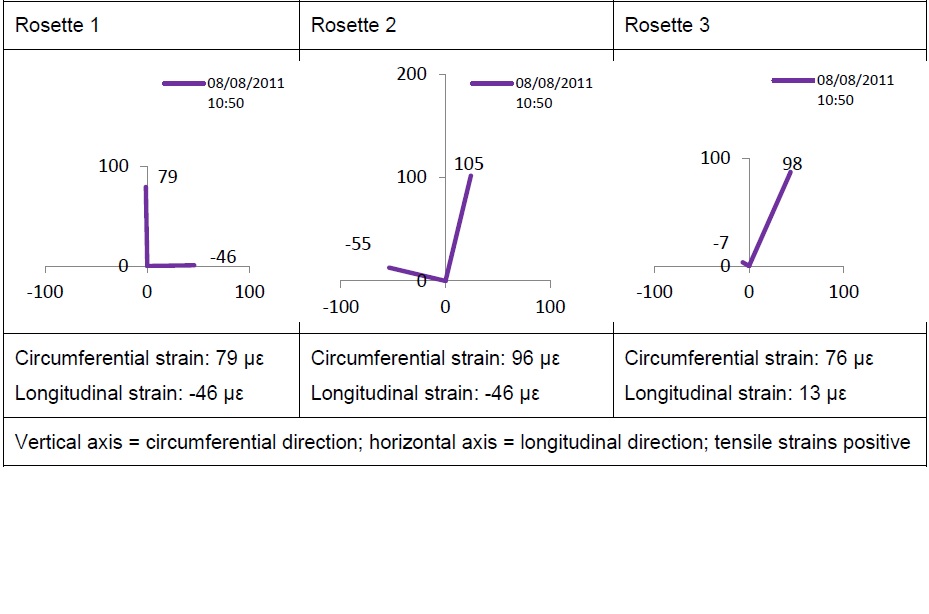
Table 5 Intermediate strain gauge results for segment 1
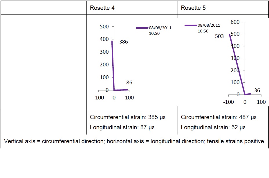
Table 6 Intermediate strain gauge results for segment 2
Results from trackside displacement transducers
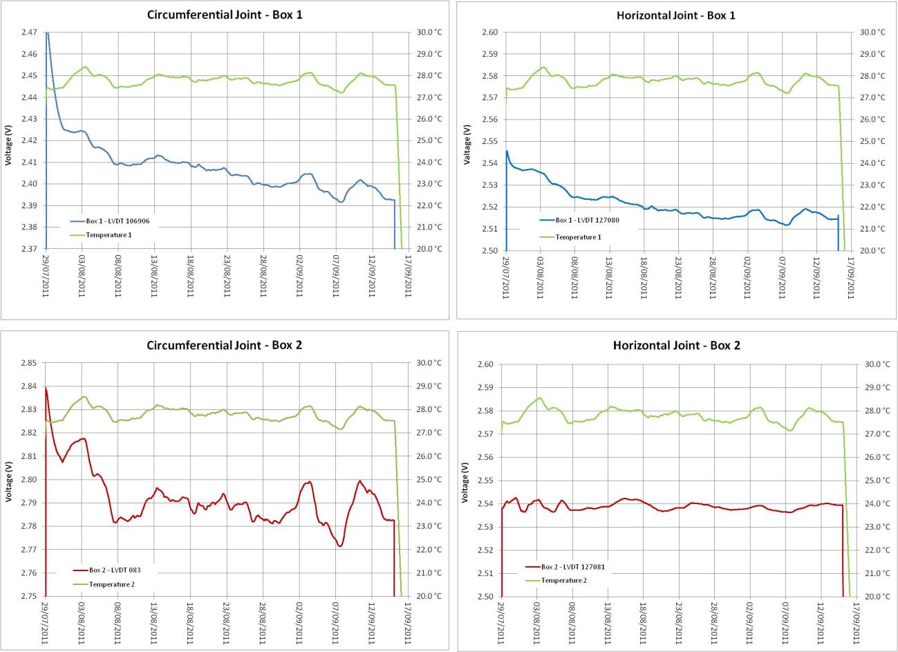
Continuous measurements of joint movement were taken by the displacement transducers over a period of six weeks. The LVDTs were affected by the diurnal temperature changes in the tunnel. Figure 20 shows the changes in voltage of the four LVDTs with the diurnal fluctuations smoothed out by using 24 hour running averages. While the voltage output was still clearly influenced by the overall temperature trends, there was also a downward shift in voltage output for three of the four LVDTs. This downward trend was steeper before the platform side segments were removed (11th August 2011) and flattened out post removal. The LVDTs were calibrated so that a reduction in voltage related to increase movement, i.e. the joint opening up.
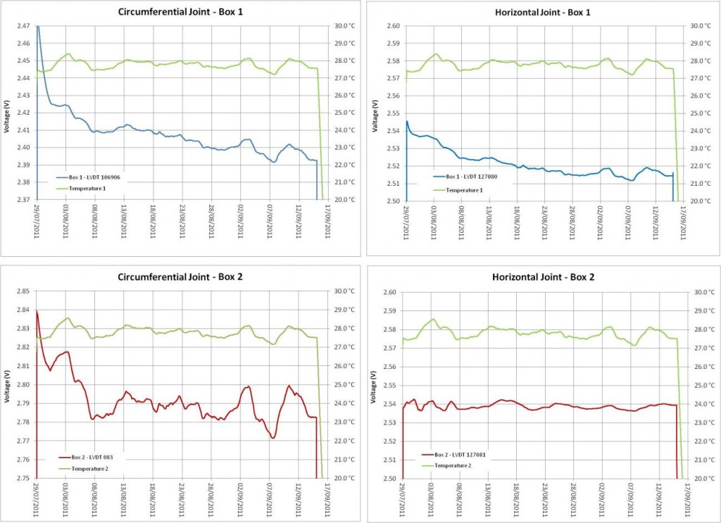
Figure 20 Comparison of LVDT trends
Conclusions
The strain release when cast iron segments were removed from a tunnel ring was measured by electrical and mechanical strain gauges. The magnitude of change in strain was similar to that predicted assuming full overburden unloading and a constant modulus of 100 GPa. Installation of strain gauges on the circumferential flanges of the segment allowed the computation of change in axial stress and bending moment of the segment due to unloading.
The use of electrical strain gauge rosettes allowed the principal major and minor direct strains on the surface of the cast iron segment to be estimated, and provided insight into the mode of deformation of the segment.
Measurements made by the LVDT displacement transducers were affected by the diurnal temperature fluctuations in the tunnel.
Notations
µε microstrain
Ω OhmsReferences
GCG (2009) Geotechnical Sectional Interpretative Report 1&2: Royal Oak to Liverpool Street. Volume 3: Drawings. Report No. 1D0101-G0G00-00551
Halcrow (2008) Northern Line cross passages/staircases long sections through staircase No.10. Drawing no. HAG-N105-8742-TUN-D-SEC-5-03426 Rev 00. Dated 15/12/2008.
Thomas, H. S. H. (1977) Measuring the structural performance of cast iron tunnel linings in the laboratory. Ground Engineering, 10 (5), 29-36.
-
Authors

Jessica Yu BE MSc DIC MICE - Crossrail Ltd
PhD student, Imperial College & Geotechnical Engineer, Crossrail Ltd.
David Potts PhD DSc FREng CEng FICE FCGI - Imperial College London
Professor of Geotechnical Engineering, Imperial College London
Jamie R Standing BEng DIC MSc PhD CEng MICE - Imperial College London
Senior Lecturer, Imperial College London
Robert Vollum MSc PhD DIC CEng MIStructE - Imperial College London
Reader in Concrete Structures, Imperial College London