Lessons learnt from the installation of field instrumentation to monitor ground response to tunnelling
Document
type: Research Paper
Author:
Michael S P Wan BEng DIC MSc CEng MICE, Jamie R Standing BEng DIC MSc PhD CEng MICE, ICE Publishing
Publication
Date: 03/11/2014
-
Read the full document
1. Introduction
Research is being undertaken by Imperial College London to investigate the effects of tunnelling on existing tunnels in London Clay. The research opportunity arose with the Crossrail construction of 21km of underground twin-bore railway tunnels through central London where the new tunnels will interface with existing networks of London Underground Limited (LUL) tunnels and other utilities tunnels. The Crossrail western tunnel section involves construction of twin tunnels using 7.2m diameter earth pressure balance tunnel boring machines (TBMs) mostly in London Clay. The tunnel drives below the existing LUL Central Line tunnels near Hyde Park allows a field investigation of the effect of new tunnelling construction on both the “greenfield” ground and the ground in proximity to existing segmental cast iron lined tunnels. The research, involving instrumentation and monitoring (I&M) fieldwork in Hyde Park and Bayswater Road, aims to provide a high quality case study of tunnel construction in London Clay and the mutual interaction of both the new and existing tunnels.
This paper describes the instrumentation scheme and the installation works. Some practical challenges faced during the installation and procurement are also discussed. The intention is that lessons learned can be applied to future similar instrumentation installation works.
2. Instrumentation site
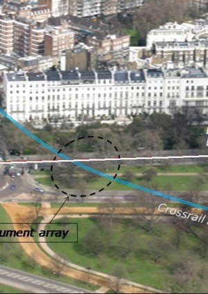
The field research site is located near Victoria Gate, the northwest corner of Hyde Park, where the Crossrail west-bound and east-bound tunnels will pass beneath the LUL Central Line running tunnels near Lancaster Gate. The actual crossing is directly beneath Bayswater Road. The location of the instrumentation site in plan and the Crossrail tunnel longitudinal section are shown in Figure 1 and an aerial photo in Figure 2.
Figure 1 – Location of instrumentation site in plan and Crossrail tunnel longitudinal section.
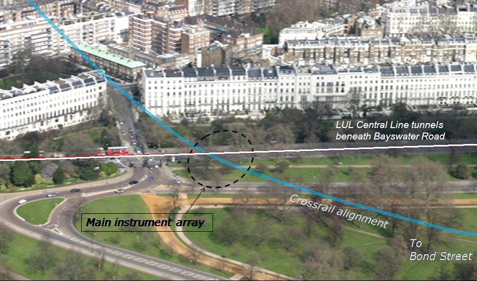
Figure 2 – Aerial photo of the instrumentation site.
3. Purpose of instrumentation
The Hyde Park instrumentation and monitoring scheme form part of a research activity and so differ from industrial instrumentation projects for construction control or decision making processes involving an observational approach (Peck, 1969). There are no trigger levels or action plans for the I&M scheme described here.
Advanced numerical modelling is a powerful method for estimating and predicting the ground response under specified loading conditions. Both numerical analyses and constitutive models should whenever possible be validated and calibrated using reliable field measurement data. The Imperial College research team are using an in-house finite element programme, ICFEP, to simulate the site conditions and construction details at Hyde Park, both with and without the presence of the existing running tunnels. The field monitoring results will be fed back into the ICFEP model.
Having recognised the purpose of the I&M scheme, it is important to choose the right types of instruments with performance levels such that the anticipated ground movements or stress changes are measured to the required accuracy and precision. Obviously, good workmanship is desirable for high quality instrument installation.
4. Borehole instruments and their installations
4.1 Instrumentation plan
A plan of the instrumentation layout is shown in Figure 3. There are in total 38 boreholes, each accommodating one or more instruments. Extensometer boreholes and inclinometer boreholes are paired so that they can measure both vertical and horizontal ground displacement at the same locations. Piezometers and spade cells have been installed around the Crossrail tunnels to measure pore water pressures and changes in earth pressures.
Most of these instruments are aligned in a main instrument array transverse to the Crossrail tunnels. There is another instrument array on the footpath of Bayswater Road parallel to the LUL Central line tunnels. These boreholes have been positioned as close to the Central Line tunnel as possible in order to see how the existing tunnels affect the ground response, as opposed to “greenfield” condition. An LUL concession application was made so that the boreholes could be drilled at as close as 1.5m away from the existing tunnel edge.
In the main array, the instruments are so positioned that the southwest part of the instruments monitor the “greenfield” ground response whereas the northeast part measure the ground response under the influence of the existing Central Line tunnels. The measured southwest half of the settlement trough would be expected to be different to that of the northeast half.
The positions of the installed rod extensometers and in-place inclinometers along the main array are presented schematically in Figures 4 and 5 respectively. Each cross in Figure 4 represents an anchor at which the subsurface settlements are measured (a maximum of eight anchors can be installed in one borehole). The anchors are largely distributed around the Crossrail tunnels, installing them around the existing Central Line tunnels was precluded by site constraints such as heavy traffic volume and Thames Water pipes on Bayswater Road. Nevertheless, it was possible to install some borehole instruments under the footpaths of Bayswater Road, where the Central Line tunnel will still influence the ground response. As shown in Figure 5, there is a similar arrangement for the inclinometer boreholes in the main array. The inclinometer and extensometer boreholes are paired (about 2.5m apart), to facilitate interpretation of the displacement data: this is particularly useful when determining displacement vectors and ground strains.
In the main instrument array, piezometers and spade cells were installed, as shown in Figure 6, around the Crossrail east-bound tunnel to monitor changes in pore water pressure and total horizontal earth pressure as the TBMs approach and pass. There are two multi-level VW type piezometer boreholes within Hyde Park, with six piezometer sensors at different depths in each. A conventional standpipe piezometer was also installed just 2m away from one VW piezometer borehole, at the same distance from the Crossrail tunnel, to verify the long-term pore water pressures recorded with the VW piezometers.
Along Bayswater Road there is another instrumentation array as shown in Figure 7. The same types of instruments were installed there to measure the response of the ground close to the existing Central Line tunnels. These boreholes are either about 3m from the LUL tunnel extrados or terminate about 1.5m above the tunnel crown. It is envisaged that the piezometers will measure the pore water pressure profile near the existing tunnels and indicate drainage effects on the steady state pore water pressure profile.
The instrument types were selected for the current Hyde Park site, bearing in mind the magnitude of changes predicted by empirical methods. While there may be other instruments and techniques available to perform the tasks, the experience of the Imperial College field monitoring team gained from previous research projects such as the Jubilee Line Extension Project and Channel Tunnel Rail Link Project played an important role in the selection process.
Figure 3 – Plan of instrumentation plan in Hyde Park and Bayswater Road.
Figure 4 – Cross-section of rod extensometer boreholes in the main instrument array (Section A-A).
Figure 5 – Cross-section of proposed in-place inclinometer boreholes in the main instrument array (Section B-B).
Figure 6 – Cross-section of piezometer and spade cell boreholes in the main instrument array (Section D-D).
Figure 7 – Cross-section of borehole instruments in the array parallel to Bayswater Road (LUL Central Line tunnels) (Section C-C).
4.2 Rod extensometers
4.2.1 Measurement principle and performance
Subsurface vertical displacements are to be measured using multi-level rod extensometers. A maximum of eight anchors, positioned at different depths, attached to stainless steel rods were installed in a single borehole. The steel rods were adjusted so that the rod heads were just below a reference head plate at the ground surface (Figure 8). The depths of the rod tips below the reference head are measured by using dial gauge, while the reduced level of the reference head plate is measured by precise levelling. Combining the dial gauge and precise levelling measurements, the reduced level of each anchor at each measurement time can be determined.
Figure 8 – Details of multi-level rod extensometer (Nyren, 1998).
Rod extensometers generally have a much higher accuracy than magnetic extensometers. As the dial gauge to be used has an accuracy of +/-0.05% full scale range (100mm), the accuracy is +/-0.05mm, compared with the +/-1mm accuracy normally achieved with a typical magnetic extensometer. The overall measurement accuracy is governed by that of the precise levelling which is about +/-0.3mm at best. Sub-millimetre accuracy is desirable at the current research site as the maximum anticipated settlement is only about 10mm.
4.2.2 Installation
The rod extensometers were installed in boreholes formed by cable percussion drilling. During the borehole drilling, the stainless steel rods, PVC sleeves and hydraulic tubing for the anchors at different depths were laid out and prepared on the ground surface by the instrumentation specialist contractor. The rods, sleeves and anchors were colour coded with duct tape to identify the anchors at different depths. Immediately after the borehole was drilled, a tremie grout pipe was put down the borehole. Then the whole assembly of the bottom-most anchor was first inserted into the borehole. Once at the required depth, the prongs of the anchor were jacked out hydraulically via the tubing to secure the anchor into the wall of the borehole. This procedure was repeated for each of the remaining anchors.
After all the anchors were fixed in the required depths, the borehole was ready for backfilling with a cement bentonite grout. Grout mix trials were conducted in the contractor’s workshop before commencement of the site work, where the grout properties and pumpability of different design mixes were tested. The grout mixes used for different types of instruments are discussed in Section 5.1. Once the backfill grout had hardened, the reference head was installed and the headworks constructed. Finally, the top of the stainless steel rods were replaced with adjustable rod heads which were set to about 50mm below the reference head. The dial gauge has a range of +/-50mm which allows measurements of maximum 50mm settlement or heave of the rods and hence anchors relative to the reference head.
4.3 In-place inclinometer
4.3.1 Measurement principle and performance
Subsurface horizontal ground displacements are measured by in-place inclinometers. Each inclinometer consists of a series of micro-electro-mechanical system (MEMS) accelerometer sensors mounted on short carriages positioned at selected intervals down a typical inclinometer casing. Each accelerometer measures the capacitance change in response to tilt and transmits the voltage change to a data-logger. The MEMS tilt sensors are left in place during and after the tunnel construction so that automated data-logging is possible. A maximum of 16 sensors were installed in one single inclinometer casing. The horizontal displacement profile along the inclinometer casing can be deduced if appropriate gauge lengths for the sensors are assumed, as demonstrated in Figure 9.
Figure 9 – Schematic presentation of in-place inclinometer (Nyren, 1998).
The MEMS tilt sensors have a measurement resolution of 2 arc seconds. Baseline monitoring after installation shows that repeated readings on a number of tilt sensors over a few days fall within a range of about 4 arc seconds, which is equivalent to about 0.08 mm for a sensor spacing of 4m (i.e. 0.02mm/m). Since that is a random error and is independent for each individual sensor, the overall repeatability for a maximum of 16 sensors would equate to individual repeatability x , which is 0.16mm over 32m (2m spacing), or 0.32mm over 64m (4m spacing).
4.3.2 Installation
Typical inclinometer casings were installed in the boreholes formed by cable percussion drilling. The inclinometer casings are ABS plastic of 59mm internal diameter and 3m length with snap couplings at the ends. Each joint is sealed with two O-rings and leak-proof to prevent ingress of the backfilling grout. Prior to placing the inclinometer casings into the borehole, a water test was performed to demonstrate that the casing joints do not leak. As the inclinometer casings were lowered down into the borehole, the casing joints were covered by two layers of duct tape as an additional seal. After aligning the casing grooves to the desired orientation (perpendicular/parallel to the Crossrail tunnel alignment), the borehole was backfilled with a cement-bentonite grout (see Section 5.1). Again prior grout mix trials were performed in the contractor’s workshop. In order to counter the buoyancy of the casing in the wet grout, they were filled with water. For deeper boreholes, the grouting was completed in two stages so that the grout at the bottom section had semi-hardened before further wet grout was pumped to complete backfilling. Finally a headworks was constructed to accommodate a data-logger. After the installation, the casing was mapped by a torpedo probe for an initial measurement of the casing inclination.
In May 2012 (almost a year later), in-place tilt sensors were installed in the inclinometer casings. Each MEMS tilt sensor is fixed within a protective aluminium tube, with O-ring seals at its ends, which is mounted on a short carriage with wheels on one side and a leaf spring on the other. The carriage could then be pushed along the keyways of the inclinometer casing and stays in position after pushing. Each aluminium tube contains one MEMS sensor measuring tilt in one plane only. For most inclinometers, only tilt measurements transverse to the TBM movement are required, and therefore a series of uniaxial tilt sensors were installed. For some inclinometers, measurements on both the longitudinal and transverse directions are required, and so two carriages were fixed orthogonally to each other.
Consecutive tilt sensors within a single borehole are connected by a signal cable so that all the sensors are connected in series with just one signal cable coming out from the inclinometer casing. The carriages were pushed down the inclinometer casing to required depths using PVC rods of different lengths. Finally the sensors were connected to a data-logger which was placed within the headworks. The frequency of the data logging was set and the data can be downloaded to a laptop from the data logger.
4.4 Vibrating wire (VW) piezometer in fully grouted borehole
4.4.1 Measurement principle and performance
The technology of vibrating wire (VW) type instruments has advanced within recent years and they are considered to have better longevity and durability than before. Historically single VW piezometers were installed within a borehole, surrounded by a sand filter and sealed for the remainder of the borehole with bentonite (Figure 10b). Recently the technique of installing them using the “fully-grouted” method, in which the VW piezometer units are embedded in a suitable cement bentonite grout, has become popular (Dunnicliff, 2008). The conventional installation method was originally for Casagrande type standpipe peizometers which require large groundwater inflow to or outflow from the standpipe (Figure 10a).
Vaughan (1969) suggests that for diaphragm type piezometers which require only very small amounts of water flow to operate, granular filters can be omitted and the piezometer sensors can be fully backfilled by low permeability grout. Mikkelsen (2002) discusses the practical side of the fully-grouted method and recommends good practice and appropriately proportioned cement bentonite grout mixes. Dunnicliff (2008) and Contreras et al (2008) report successful installation and monitoring of piezometers installed by the fully-grouted method at various sites around the world. A schematic of borehole piezometers installed by the fully-grouted method is shown in Figure 10c.
The fully-grouted method has a major advantage in that the straightforward backfilling procedure allows multi-level piezometer sensors to be installed in one single borehole. This makes it possible to obtain a pore water pressure profile with depth at a single borehole location. This significantly reduces the number of boreholes required.
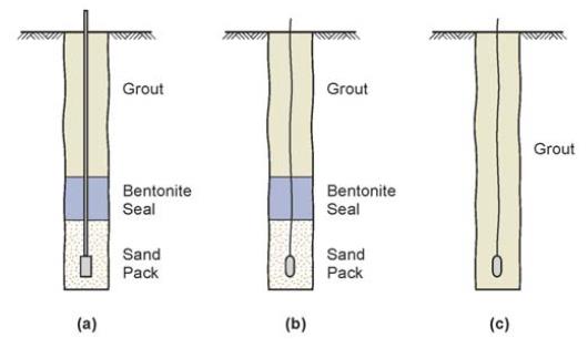
Figure 10 – Schematic presentation of (a) traditional standpipe piezometer, (b) diaphragm type piezometer with traditional installation, (c) diaphragm type piezometer in fully-grouted borehole (Contreras et al, 2008).
4.4.2 Installation
Prior to installation, the VW piezometer sensors were placed in de-aired water at ground level and pre-installation ‘zero’ readings taken. This allows future readings from these sensors to be referenced to atmospheric pressure. The porous filters of the piezometers were de-aired by boiling for at least 2 hours before the installation. On site, six sensors were installed in a single borehole. PVC grouting pipes of 75mm diameter were used for backfilling and also for attaching the sensors at different depths. With the grouting pipe lying on the ground, the depths of the sensors were marked and small slots were cut in the pipes for the signal cables to pass inside the grouting pipes. The sensors were then fixed onto the grouting pipes by cable ties, the signal cables fed through inside the pipes and the cut slots sealed by at least two layers of duct tape. As the grouting pipes were lowered down into the borehole, the joints of the grouting pipes were connected and sealed by duct tape. Low permeability cement bentonite grout (see Section 5.1) was then pumped via the grouting pipe to the base of the borehole and the piezometer assembly was fully grouted. During backfilling, the sensors were monitored by a hand-held VW readout unit to check that they were not over- stressed by the wet grout. The signal cables were labelled with duct tapes of different colours to identify the depths of the sensors. Finally, the cables were connected to data-loggers housed within a headworks.
5. Technical challenges
Achieving research-quality instrumentation installations at times led to additional technical and sometimes contractual challenges to those for more standard ground investigation and instrumentation projects. Some of the more salient challenges and their solutions are now discussed.
5.1 Grout mixes for borehole backfilling
Depending on the instrument types, the backfilling grouts should have different mechanical properties relative to the surrounding ground. Mikkelsen (2002) argued that for extensometers, the grout should have stiffness equal to or smaller than the surrounding ground, while for inclinometers, a stiffer grout is desirable. For piezometers fully grouted in a borehole, Vaughan (1969) proved analytically that the error associated with pore water pressure measurement is insignificant if the grout permeability is not larger than 20 times the ground permeability. More recently, Contreras et al (2008) demonstrated using finite element analyses that the grout permeability could actually be 1000 times higher than that of the ground before significant errors in pore water pressure measurements occur. Therefore, three types of grout mixes were chosen for backfilling the extensometer, inclinometer and piezometer boreholes. In addition to the stiffness and permeability requirements, the grouts should also be readily mixable and liquid enough to be pumped through the hose and tremie pipe to the borehole.
Grout properties such as stiffness and permeability are affected by many factors such as the material composition (cement type, fineness of bentonite powder, water acidity etc), mixing equipment, mixing sequence and even mixing temperature. The initial grout mixes determined from the pre-installation trial mixes in the contractor’s workshop were found to be too thick to be pumped through the tremie pipe on site. Checks were made to ensure that the materials were the same for the trial mixes at workshop and the actual mixes on site; the same sequence of the mixing was followed; the same model of the mixer was used too. It was believed the difference in the grout consistency could have been due to small temperature differences (winter to summer) and perhaps more significantly the trial grout mixes in the workshop were not pumped through the same length of grout pipe as on site to check the pumpability. This latter effect was further compounded on site as the grout pump had additionally to overcome the hydraulic head of the wet grout in the borehole.
Further grout mix trials were performed on site, using the same materials and mixer but under the site environment and using a stronger piston pump. Successful revised grout mixes were determined but this took time and led to delays in the overall programme of work.
5.1.1 Properties of trial grout mixes
Ordinary Portland cement, sodium-bentonite powder and pulverised fly ash (PFA) were used for the grout. For both the initial workshop trial and the final site trial, a mixing sequence as recommended by Mikkelsen (2002) was followed: mixing bentonite at the end after cement and fly ash. The mixing procedure started by adding a measured quantity of clean water into a mixing pan. The proportioned cement was then gradually added and mixed thoroughly, followed by adding and mixing the fly ash. Finally the bentonite powder was slowly added, stirring the mixture constantly, to break down any lumps of bentonite that formed.
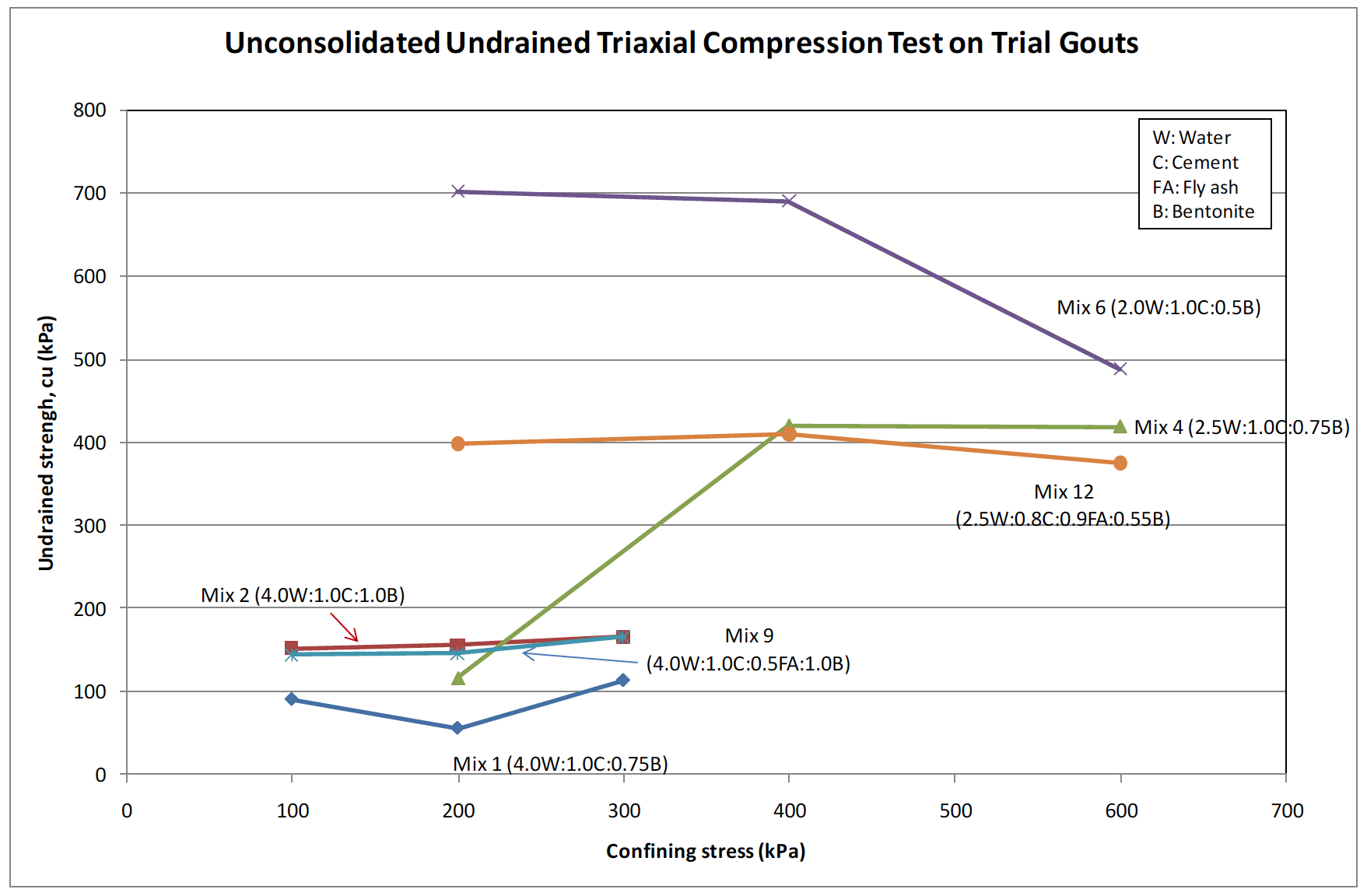
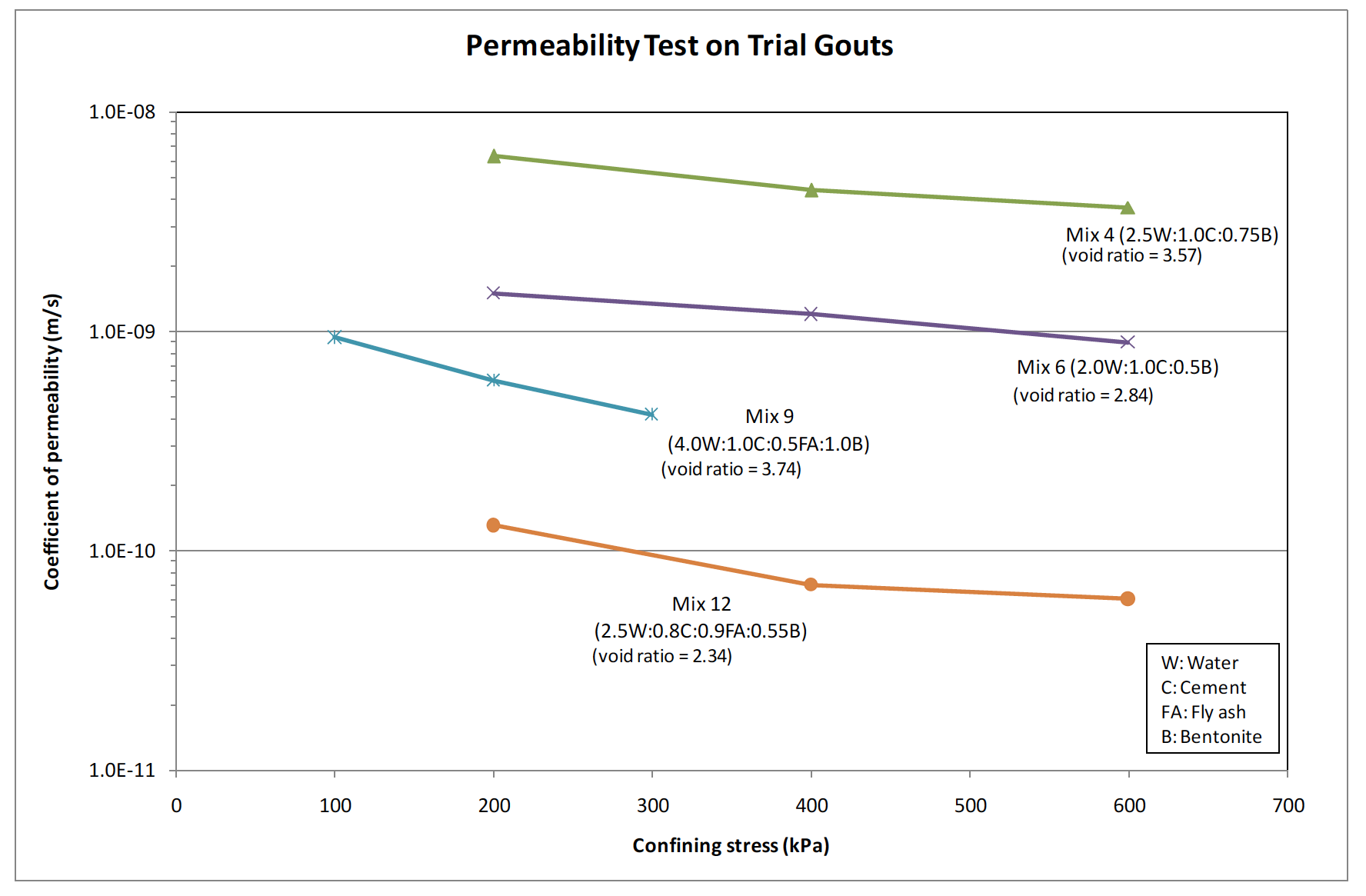
The initial workshop grout trial involved twelve mixes, of which six were not pumpable using a progression cavity pump that the contractor proposed to use on site. Samples of 100mm diameter were prepared for the other six pumpable grouts and tested in laboratory for unconsolidated undrained shear strength and permeability using a triaxial apparatus. The details of the grout mixes and test results are summarised in Table 1 and Figures 11 and 12.
Although it is compatibility of stiffness of the grout and the ground that is sought, usually comparisons are made in terms of undrained strength for simplicity (because of the varying nature of stiffness with strain).
Mix No. 1 2 4 6 9 12 Mix proportion by mass (Water:Cement: Fly ash: Bentonite) 4.0 : 1.0 : 0.0: 0.72 4.0 : 1.0: 0.0: 1.0 2.5 : 1.0 : 0.0 : 0.74 2.0 : 1.0 : 0.0 : 0.5 4.0 : 1.0 : 0.5 : 1.0 2.5 : 0.8 : 0.9 : 0.55 *UU triaxial compression test Curing time (days) 59 58 38 38 32 32 Average sample void ratio 5.14 4.93 3.50 3.03 4.16 2.76 (Confining pressure)/ UU triaxial shear strength (kPa) (100) 91 (100) 152 (200) 117 (200) 702 (100) 145 (200)398 (200) 56 (200) 156 (400) 421 (400) 691 (200) 146 (400) 410 (300) 114 (300) 166 (600) 420 (600) 489 (300) 166 (600) 375 **Permeability test in triaxial apparatus Sample void ratio N/A N/A 3.57 2.84 3.72 2.34 (Consolidation pressure, kPa)/ Coefficient of permeability (m/s) N/A N/A (200) 6.3×10⁻⁹ (200) 1.5×10⁻⁹ (100) 9.4×10⁻¹⁰ (200) 1.3×10⁻¹⁰ N/A N/A (400) 4.4×10⁻⁹ (400) 1.2×10⁻⁹ (200) 6.0×10⁻¹⁰ (400) 7.0×10⁻¹¹ N/A N/A (600) 3.7×10⁻⁹ (600) 8.9×10⁻¹⁰ (300) 4.2×10⁻¹⁰ (600) 6.0×10⁻¹¹ *UU = Unconsolidated undrained triaxial compression test on 38mm specimens
**100mm diameter specimens were consolidated under different cell pressures before permeability tested under a constant pressure gradient. The tests were performed in accordance to BS1377 Part 6: 1990 Clauses 5.3, 5.4, 5.5.2.2 to 5.5.2.7 and 6.
Table 1 – Details of trial grout mixes and properties.
As indicated in Table 1 and Figure 11, generally the shear strengths of the grouts are insensitive to the confining cell pressures. In the cases of mix numbers 1, 4 and 6 there was one sample in each set of tests that had a significantly lower strength than the others. As there is no trend in the lower strength with cell pressure and as only a single sample was prepared for each cell pressure, it is assumed that these lower strengths are not representative. In general, the grout shear strength decreases with increasing water-cement ratio (n.b. mixes with higher water-cement ratios (and PFA) produce grouts with higher void ratios). Similarly, grouts with a lower water-cement ratio and hence lower void ratio generally have a lower permeability, although the bentonite proportion also influences permeability as can be seen from Figure 12.
Based on the results from the initial grout trials and ground investigation reports, Mix 2 and Mix 4, respectively having smaller and larger shear strengths than the surrounding soils, were considered suitable for backfilling extensometer boreholes and inclinometer boreholes respectively. Mix 6, having a coefficient of permeability of 1×10⁻⁹ m/s, was considered less than 100 times more permeable than the surrounding London Clay (for which the lowest permeability was considered to be about 1×10-11 m/s) and therefore considered suitable for backfilling VW piezometer boreholes.
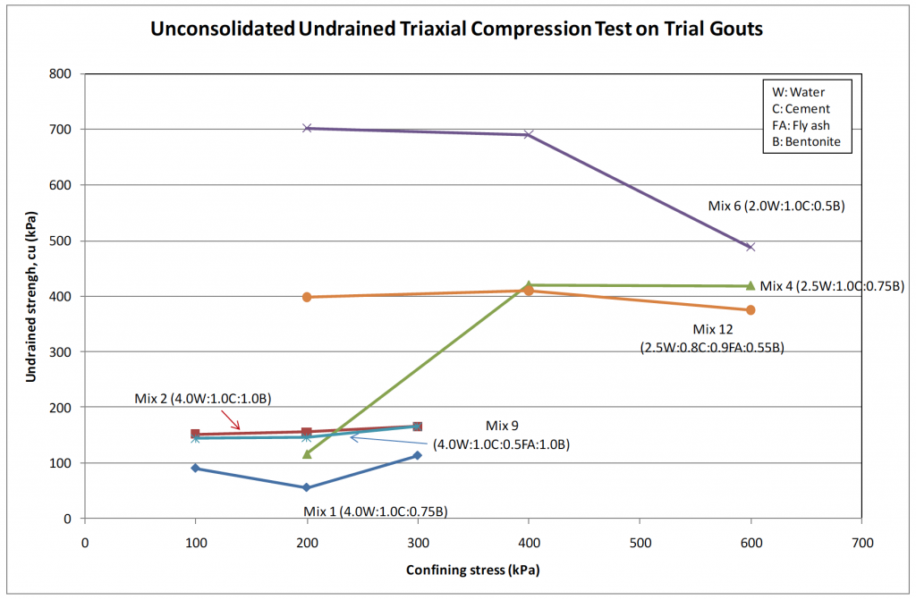
Figure 11 – Undrained shear strengths of 38mm specimens of trial grout mixes.

Figure 12 – Coefficient of permeability of trial grout mixes.
The lack of pumpability of the initial trial mixes on site using the original progression cavity pump led to modifications being made to the grout mixes for extensometer and inclinometer boreholes primarily involving reducing the bentonite quantity and adding PFA. The pumpability of the revised mixes was tested by pumping the grouts into an abandoned 30m borehole using a stronger piston pump. The final grout mix proportions used are shown in Table 2.
Borehole backfill Water Cement Fly ash Bentonite Extensometer 4.0 1.0 0.5 0.9 Inclinometer 2.5 0.8 0.9 0.5 VW piezometer 2.0 1.0 0.0 0.5 Table 2 – Final grout mixes proportion by mass.
Ideally grout mix trials should be performed using the same materials and equipment on site prior to the grout backfilling. This would involve careful planning of site activities as it could take weeks to obtain representative laboratory testing results. Allowance in grout pumpability should also be made to take account of the need to overcome the wet grout hydraulic head.
5.2 Encountering obstructions of Thames Water pipe
During the borehole drilling, shallow ground obstructions were encountered below the Bayswater Road pavement. Prior to drilling on the southern side of Bayswater Road, several inspection trenches were excavated to expose an existing water pipe as required by Thames Water to determine the exact size and location of the pipe. It was found to be a cast iron pipe of 600mm diameter, with the depth of the pipe crown ranging from 0.2m to 0.6m below ground level in the vicinity of the boreholes. The pipe is a major water main and so Thames Water required the boreholes to be drilled in a controlled manner outside a set distance from the pipe. As the water main runs exactly above the LUL Central Line west-bound tunnel along Bayswater Road, it was not possible to install the boreholes and instruments in close proximity to the existing tunnel.
In order to assess potential effects on the water main of borehole drilling, a trial was performed within Hyde Park, measuring ground vibration. Two 0.5m deep pits were excavated at 1.5m and 3.0m from the borehole. Ground vibrations in terms of peak particle velocity (ppv) were measured using geophones at the bottom of the pits during various steps of borehole drilling. Potential mitigation measures to reduce vibration were investigated during the measurements, including digging a deeper inspection pit before starting cable percussion drilling, advancing the casing by surging instead of hammering, reducing the rate of hammering and using more water to facilitate penetration of the casing close to the pipe. It was found that the maximum vibration occurred when the casing was hammered into the top of London Clay at about 5m depth. A ppv of 4.4m/s was measured at 1.5m from the borehole when the casing was rapidly struck. However, if a 2-3 second delay was allowed before each casing strike, reduced ppv’s of 3.9m/s and 3.5m/s were measured at 1.5m and 3.0m respectively from the borehole. The results indicated that risk of damage to the water main should be sufficiently low at 3m from the borehole with the above-mentioned precautionary measures. No damage to the water main was reported during the work. Clearly, when utilities pipes are expected, early engagement and close liaison with utilities companies is vitally important.
5.3 Time of completion of instrument installation
Ideally, drilling, installation of instruments and backfilling of the borehole should be completed in as short a period of time as possible, preferably within one day, to minimise disturbance to the ground around the borehole due to stress relief and desiccation. This helps ensure that a high instrument conformance is achieved.
Finishing a 30m or deeper borehole with instrument installation and backfilling within a day was not usually practically feasible, as there was a strict control on the working hours (8am to 6pm) within Hyde Park. A compromise was to complete the installation over a two day period. A borehole would be started and left open overnight down to 30m below ground, with the borehole being cased over the depth of Terrace Gravels, taking account that the London Clay sub-unit B2 to this depth is relatively more stable than the underlying A3ii London Clay sub-unit. The borehole drilling was completed the next morning and installation of the instruments and grout backfilling of the borehole was finished by the end of the afternoon.
Clearly, early discussions with the contractor about specific project requirements and any site restraints help achieve workable solutions.
5.4 Borehole diameters
Smaller diameter boreholes usually are more advantageous than larger ones as faster, more effective drilling can be achieved with less disturbance to the ground. On site, 200mm diameter boreholes were drilled initially, although the instruments were able to fit into 150mm boreholes. The main reason was to cover the risk of abandoning the borehole in case of borehole wall collapse: with a 200mm diameter borehole it is possible to continue drilling with 150mm casings. If the borehole were started with 150mm casing, there would be a risk of abandoning the whole borehole if a borehole collapse occurred which would be beyond the contractor’s control.
Drilling rates are much slower for 200mm compared with 150mm boreholes, especially when stiffer strata or claystones are encountered. In order to minimise the ground disturbance and improve the construction progress, it was agreed that an Engineer’s instruction be given to the contractor to drill boreholes of 150mm diameter. Any abandoned hole and redrilling due to borehole collapse induced by factors uncontrollable by the contractor would be payable works. This was a re-allocation of the risk from the contractor to the client. Based on earlier records and experience of drilling in the Hyde Park area, the chance of encountering water strike was deemed to be low. In the end no collapse of boreholes occurred at the site.
6. Summary and conclusions
As part of the work of Crossrail ground investigation Package 16A, high-quality borehole instrumentation was successfully installed in Hyde Park and Bayswater Road. Reasons for instrument selection are given and discussed in the paper. An important factor for achieving good conformance of the instrumentation to the surrounding ground conditions is the choice of grout for backfilling the boreholes. Ideally for extensometers and inclinometers the grout should have a compatible stiffness to the ground, although usually it is the grout strength that is compared with ground strength. Equally grout and ground permeabilities should be compatible for piezometer installations. A number of grout mixes were trialled and the final choices were made according to strength and permeability criteria as well as practical mixing and pumping considerations. Other issues that had to be taken into account are also described (sensitivity of a cast iron water main, time constraints and optimum borehole diameter). At the time of writing this paper, more than 12 months of baseline monitoring work has been completed, confirming the accuracy of the various instruments and measurement systems and allowing thermal and seasonal effects to be assessed.
Acknowledgements
The authors would like to acknowledge Crossrail and the Engineering and Physical Sciences Research Council (EPSRC) who are major sponsors of the research project at Imperial College. Many thanks are due to the Imperial College research team, in particular Professors John Burland and David Potts, for their contributions in discussing the choice and layout of the instrumentation. A thoughtful review and comments on the instrumentation plan from Mr. John Dunnicliff is also greatly appreciated. The support provided by the Royal Parks and Westminster Council during the installation work is gratefully acknowledged. The successful Hyde Park instrumentation would never be achieved without the diligent work by the Package 16A Contractor, Fugro Engineering Services, and specialist sub-contractors Construction Monitoring Control Systems (CMCS) Limited and ITMsoil. The Engineer, Arup Atkins JV, in particular Ms. Vicky Hope and Mr. Paul Braddish, made enormous efforts in both the procurement and supervision of the work. Special thanks are reserved to the experienced crew of drillers, especially Mr. Ian Shortland, whose vast experience and great technique of drilling in the London Basin proved to be very essential to achieving the high quality installation.
List of Abbreviations
EPBM earth pressure balance machine
EPSRC Engineering and Physical Sciences Research Council
ICFEP Imperial College Finite Element Program
I&M instrumentation and monitoring
LUL London Underground Limited
MEMS micro-electro-mechanical system
TBM tunnel boring machine
PFA pulverised fly ash
ppv peak particle velocity
VW vibrating-wireReferences
Contreras, I. A., Grosser, A. T. & Ver Strate, R. H. (2008) The use of the fully-grouted method for piezometer installation, Part 1 and Part 2. Geotechnical News. (June), 30-40.
Dunnicliff, J. (2008) Discussion of “The use of the fully-grouted method for piezometer installation” by Contreras et al (2008). Geotechnical News. (June), 38-40.
Mikkelsen, P. E. (2002) Cement-bentonite grout backfill for borehole instruments. Geotechnical News. (December), 38-42.
Nyren, R. (1998) Field measurements above twin tunnels in London Clay. PhD thesis. Imperial College London.
Peck, R.B (1969) Advantages and limitations of the observational method in applied soil mechanics, Geotechnique, 19, (1), 171–187.
Vaughan, P. R. (1969) A note on sealing piezometers in boreholes. Geotechnique. 19 (3), 405-413.
-
Authors

Michael S P Wan BEng DIC MSc CEng MICE - Crossrail Ltd
Geotechnical Engineer at Crossrail, Postgraduate Researcher at Imperial College London
Jamie R Standing BEng DIC MSc PhD CEng MICE - Imperial College London
Senior Lecturer, Imperial College London