What need for temperature control and ventilation to battery rooms?
Document
type: Technical Paper
Author:
Matthew David BSc CEng MIMechE MCIBSE, ICE Publishing
Publication
Date: 30/09/2017
-
Read the full document
1 Introduction
The paper proposes the minimum performance requirements for the temperature range and ventilation of rooms containing the batteries supporting Uninterruptible Power Supply, UPS, systems. It is applicable to Stations, Shafts, Portals and any building using sealed-for-life valve regulated lead acid battery cells
With an agreed set of minimum performance requirements the opportunity exists to:
- Drive out unnecessary complexity of installation.
- Drive out unnecessary complexity of operation.
- Gain more consistency of design and application.
- Reduce capital and operational expenditure.
2 The Battery Room
2.1 Rooms Containing Batteries
Batteries supporting the main UPS systems are contained in either a room dedicated to batteries or a room containing the batteries and other equipment such as the UPS inverter and Communication equipment. These rooms are generally designated as follows:
- BAT – Battery Room
- UPS – Uninterruptible Power Supply
- ESR – Emergency Switch Room
Other equipment will contain or require batteries. These tend to be small and would be located in the room of the equipment they serve, for instance:
4. CER – Communication Equipment Room
5. SES-R – Signalling Electrical Supply Room
6. Fire Alarm panel
7. SR – Automatic electrical switches
2.2 Ventilation
In many cases a dedicated mechanical ducted air extract system would be designed for the rooms containing batteries that support the UPS system.
In some cases, as for the Crossrail Shafts, the general mechanical ventilation extract system serves the room with the batteries.
2.3 Temperature Range
Varying temperature ranges have been designed. Sometimes the means of control is by fan coils, being cooled by either Variable Refrigerant Flow (VRF) or chilled water (CHW), and in some cases it is by all air systems, either cooled and heated or heated only.
The all air systems will not provide the same accuracy of temperature control as the fan coils.
3 Standards and Guides
3.1 Standards
The LU Standard 1-068 A3[1] states under section “3.5 Ventilation”:
3.5.1 Natural ventilation is to be provided to non-public, normally occupied areas wherever practicable. To avoid the costs and maintenance commitment, mechanical ventilation should be avoided.
3.5.2 Ventilation shall be taken from and to atmosphere where economically viable and practicable.
3.5.8 Where ventilation routes pass between fire compartmented locations, means will be provided to meet the LU fire standards.
3.5.9 For plant and storage areas means of ventilation shall be provided to prevent the build up of stale air, battery gases, condensation and other contaminants. In rooms which are not normally occupied, ventilation may be achieved through doorways where these are opened at regular intervals where it can be demonstrated that the number of air changes achieved will meet the ventilation needs of the space. Staff areas and plant and storage rooms should not be used as ventilation routes for adjacent locations. If air is required to pass through such a location, it should be ducted throughout.The Guidance document to this standard, G-074[2] uses the statement “Ventilation rate should be determined from the lower explosive limit calculations” when dealing with this type of room.
There are known British Standards or CIBSE Guides that guide or dictate the design of a ventilation system serving battery rooms. ASHRAE Applications gives some guidance.
3.2 LUL G-085 Fire Safety Requirements
The following document provides some guidance on how to assess the ventilation requirement:
LU G-085 Code of practice – Fire Safety of Materials and Fire Safety of Specific Items and Materials Used in the Underground, Revision No: 3 [3] Issue Date: March 2010, Section 3.2.1.3 Emission and build-up of hydrogen gas.
4 Design
4.1 Normal Operation
4.1.1 Temperature Control
Valve regulated lead acid batteries have been designed to optimise their charge capacity and their operating life. This has been optimised at a room temperature of 20oC. With an increase in room temperature the charge capacity increases and life reduces. With a decrease in temperature the charge capacity reduces and the life increases.
Some manufacturers quote that every increase of 10oC above 20oC halves the battery life.
The charge capacity reduces only a little down to 15oC. Below this the reduction is more dramatic.
The room temperature is influenced by the following means of temperature control:
- The amount of air introduced to the room
- How the temperature of that air is controlled,
- The fluctuation of heat load from the batteries and other equipment in the room
- The influence of external environmental conditions on the fabric of the room.
The batteries demand the tightest control of temperature range of all the equipment, including UPS inverters, switch gear and communications equipment.
Whilst it would appear that a tight temperature range is required it may be the case that the following be applied:
Minimum temperature: 15oC
Maximum continuous temperature: 25oC
Maximum Operating Temperature: 40oC DB
If 25oC is to be applied a means of mechanical cooling is required. A ventilation only system with outside air temperatures of 30oC+ in the summer would exceed the upper limit.
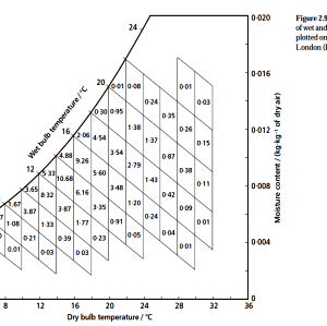
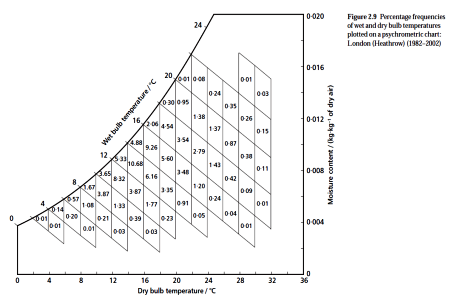
The external/ outside air temperature frequency is shown in Figure 1.
Reference CIBSE Guide A[4]

For reference:
One year= 8760 hours
One 30 day month= 720 hours
One week= 168 hours
One day= 24 hours
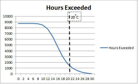
Figure 1 – Annual External/ Outside Air Temperature Occurrences
Using Figure 1 the maximum continuous temperature could be modified as:
Maximum continuous temperature: 25 oC allowing short periods exceeding this of up to 4% of a year.
By inspection of Figure 1 this criteria would allow a ventilation only system to be designed. The battery life then would be dictated by the annual variation in temperature. These ‘short periods’ need to be defined with the battery manufacturer. The implications of doing this need to be fully understood by all parties if pursued for future projects.
4.1.2 Ventilation
The off-gassing of batteries can be calculated. The minimum air flow rate for ventilation of a battery location or compartment shall be in accordance with European Standard EN 50272 [5] . From this the hydrogen rate can be calculated for each room. The rates are small. Anecdotal evidence suggests that if the door was opened on a weekly basis this would be sufficient to keep the atmosphere below the lower explosive limit.
Figure 2 is an example of a hydrogen gassing rate calculation.
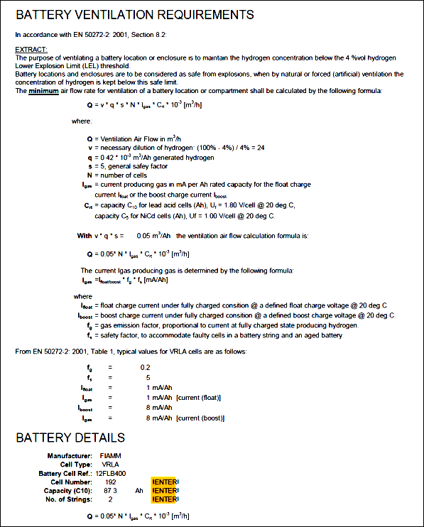
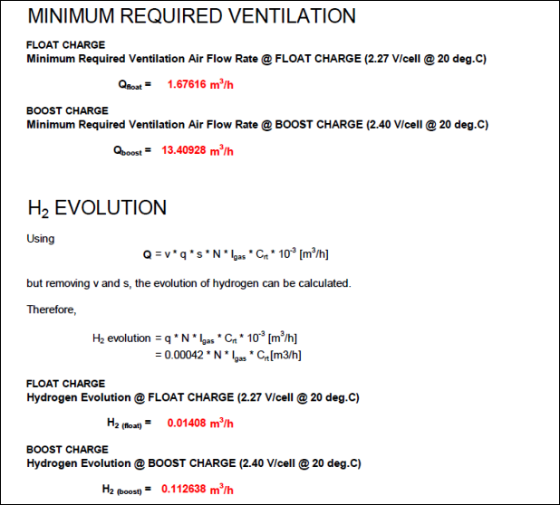
Figure 2 – Typical Calculation of Hydrogen Gassing Rate
4.1.3 System Redundancy
The battery room is a critical to the operation of the station, Shaft and Portal and so demands a redundant temperature control system for normal operation.
4.2 Emergency Operation
The means by which ventilation is achieved will dictate whether or not the battery room ventilation system continues to be enabled or disabled on a fire occurrence. These batteries are not critical to the operation of life safety equipment or the continued operation of the railway in an emergency situation, which relies on either of the electrical supplies, A or B, being available.
Where possible the cooling to these rooms should continue but again it will not be critical to the operation of life safety equipment nor the continued operation of the railway in such a situation.
4.3 Critical Occurrence Operation
On loss of both electrical supplies, A & B, the UPS and batteries will come into their own.
The ventilation of hydrogen is not critical to the operation of life safety equipment or the continued operation of the railway in such a situation. It should not be supported by UPS.The design of battery rooms should be completed using passive heat dissipation so that no UPS support to cooling equipment is required.
5 Future Work
The following should be investigated further on all projects where battery rooms are to be designed.
5.1 Future Projects
Battery rooms should be designed into buildings such that they can be naturally ventilated.
Design rooms to provide passive heat dissipation in the event of fire and Critical Occurrence.
Design:
5.1.1 Mechanical cooling
Agree room design temperatures of:
Minimum: 15oC
Maximum: 25oCCombine the batteries with the UPS inverters so that a common mechanical cooling system can be used.
5.1.2 Ventilation only
Agree room design temperatures of:
Minimum: 15oC
Maximum: 25oC allowing short periods exceeding this of up to 5% of a year.Understand the implications of this on battery life and ensure this is written into the relevant specifications.
Design separate rooms for batteries so they need only be ventilated. This would minimise the heat gain to the room.
Design the ventilation to maximise the life of the batteries.
Design and specify batteries with an agreed operating life with operation at temperatures higher than 25oC.
Action: Write a performance specification very early in the design process. Engage very early with the architect to arrange rooms appropriately.
6 Conclusions & Recommendations
The following performance criteria (in Italics) are the minimum requirements proposed for the design of a battery room.
6.1 Normal Operation: Minimum Performance Criteria
6.1.1 Temperature Control
Minimum Requirements
The widest possible temperature range for the battery room shall be designed to optimise the performance of the batteries.
The mechanical systems shall have N+1 redundancy.No room air humidity control is required.
Commentary
Where mechanical cooling using VRF or chilled water is used then some dehumidification will be obtained.If possible, practical and where an operational advantage can be gained, agree only to ventilate the room based on:
Maximum: 25oC allowing short periods exceeding this of up to 5% of a year.Understand the implications of this on battery life and ensure this is written into the relevant specifications.
The means by which each room is cooled shall be chosen with respect to the following criteria:
- Space Allocation
- Operation on Failure of Plant
- Operation during Maintenance
- Capital Cost
- Operating Cost
6.1.2 Ventilation
Minimum Requirements
Battery rooms shall be ventilated to external atmosphere in accordance with EN 50272 using the gassing rate of batteries as confirmed by the framework supplier.The mechanical systems shall have N+1 redundancy, if the ventilation is by mechanical means.
A suitable make up air supply shall be designed so that a negative pressure is normally experienced in the room.
The risks shall be described and assessed qualitatively.
Commentary
The means of ventilation shall be to the designer’s discretion. A dedicated extract system is not necessary.The system designed should not allow the extracted gas mixture to be recirculated to other rooms but exhausted directly to outside.
The system designed to do this shall provide 24/7 operation.
6.1.3 Space Allocation
Minimum Requirements.
Adequate space for plant maintenance and replacement shall be provided, without affecting the operation of the Station.6.1.4 Operation on Failure of Equipment
Minimum Requirements
The Battery Rooms are Critical Rooms and system redundancy is required for temperature control in normal operating conditions.
Commentary
The operation of the Station shall be unaffected by:- Failure of one fan
- Failure of one Fan Coil
- Failure of one chilled water air cooled chiller.
- Failure of one VRF chiller/condenser.
- Failure of one chilled water pump
- Failure of a component in an air handling unit.
The maintenance of the Station shall be unaffected by:
- Maintenance of one fan
- Maintenance of one Fan Coil
- Maintenance of one chilled water air cooled chiller.
- Maintenance of one VRF chiller/condenser.
- Maintenance of one chilled water pump
- Maintenance of a component in an air handling unit.
6.2 Emergency Operation: Minimum Requirements
6.2.1 Temperature Control
Minimum Requirements
The battery rooms shall not be allowed to ‘overheat’ to an extent that the equipment in the rooms fails to operate.6.2.2 Fire Alarm
Minimum Requirements
Fire compartmentation shall be maintained and smoke migration minimised in accordance with, but limited to the Fire Strategy, BS 9999 [6] and Building Regulations Approved Document B [7].On a confirmed fire alarm cooling to battery rooms may be disabled, but this is not a necessity.
If cooling is achieved normally by ducted air systems then they may be disabled.
On confirmed fire alarm, ventilation to the battery room may be disabled.
The fire strategy and Cause & Effect study shall confirm the minimum requirements of the HVAC systems in a fire.
A mechanical smoke clearance system is not required unless specifically stated in the Fire Strategy report.
Commentary
It is recommended that the air ventilation systems are stopped. The batteries will produce very little heat and gas during this occurrence.Fire rated ductwork and Fire Dampers should be used to provide fire compartmentation. It is not necessary that the system operate in the event of a fire occurring.
6.3 Critical Occurrence: Minimum Requirements
Minimum Requirements
In the event of loss of electrical power from the A&B electricity grid supplies, the Battery Rooms shall not reach a temperature whereby the equipment will cease to operate.Commentary
Design the room to passively cool with an uncontrolled design temperature up to a maximum that the equipment can tolerate.7 References
[1] LU Standard 1-068 A3 Mechanical Building Services, Utility Provision and Energy Management in London Underground, May 2011
[2] G-074 Guidance Document For 1-068 Mechanical Building Services, Utility Provision and Energy Management in London Underground, April 2011
[3] LU G-085 Code of practice – Fire Safety of Materials and Fire Safety of Specific Items and Materials Used in the Underground, Revision No: 3, September 2013
[4] CIBSE Guide A The Chartered Institution of Building Services Engineers London, 2007
[5] EN 50272-2, 2002 Safety requirements for secondary batteries and battery installations — Part 2: Stationary batteries
[6] BS 9999: 2008 Code of practice for fire safety in the design, management and use of buildings
[7] The Building Regulations 2000 Approved Document B Fire safety – Volume 2 Buildings other than Dwellinghouses. -
Authors

Matthew David BSc CEng MIMechE MCIBSE - Crossrail Ltd
Matthew David is a mechanical engineer with the Chief Engineers Group. He is responsible for the assurance of the design, installation, commissioning and handover of the mechanical systems for the stations, shafts and portals. He has been with Crossrail since March 2013. He has spent the previous 31 years designing buildings, of many types, around the world.
