A regional scale groundwater monitoring programme for the Crossrail project: strategy and implementation
Document
type: Technical Paper
Author:
Dr Ursula Lawrence PhD Eur.Geol C.Geol FGS C.Sci, Chris Menkiti, Mike Black BSc(Hons) MSc CSci CGeol FGS, ICE Publishing
Publication
Date: 31/08/2016
-
Read the full document
1 Introduction
The Crossrail project is a new underground railway crossing London from west to east. The project involves the construction of 2x21km of twin bore tunnel, 5 portals and 8 new underground stations. Supporting the railway are 20 cross passages and 5 permanent shafts. Additionally, temporary construction shafts were required to facilitate access to tunnelling works and a further 21 shafts for compensation grouting. In the west the route is entirely within tunnel running above and below existing tube lines at Paddington, Bond Street, Tottenham Court Road, Farringdon, Liverpool Street, Whitechapel and Canary Wharf. In the east, the route alternates between surface and tunnel by utilising the former North London Line route through Silvertown, the Connaught Tunnel and North Woolwich. The route continues in tunnel under the River Thames to Woolwich and beyond to Plumstead.
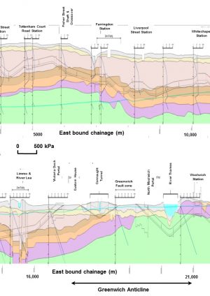
Figure 1 shows the geology cartoon illustrating the juxtaposition of the tunnel alignment with the geology. Figure 2 shows the plan alignment for the tunnelled section. The route runs through typical London Basin geology starting in the west in the London Clay Formation. East of Fisher Street shaft the geology is uplifted by the Soho anticline and the route reduces in elevation for the approaches to Farringdon Station. This brings the route down through the London Clay Formation and into the Lambeth Group. Beyond Farringdon, through to Canary Wharf Station and north east to Pudding mill Lane, the route roughly follows the boundary between the Lambeth Group and the London Clay Formation, crossing back and forth between them. South east of Canary Wharf, the tunnels descend under the river Lea. This coincides with the Greenwich syncline and the Plaistow Graben resulting in the route ascending the profile through to the London Clay Formation and back down the profile to the Chalk at the eastern end of the Connaught Tunnel. Further south east, the Greenwich Anticline brings the Chalk Group to the surface and this dominates the remainder of the route under the Thames through Woolwich Station and on to Plumstead.
2 Ground investigations
The ground investigations to inform design began in 1992. 231 piezometers were installed in four ground investigations (Packages A to D) and monitored until 1998 when the project was placed in safeguarding awaiting the go-ahead from government to re-commence. Virtually all of these boreholes were lost during this time. The boreholes had primarily been drilled in public highways and had been lost due to resurfacing works. The project recommenced in 2002 with a substantially modified alignment and ground investigations began shortly thereafter. Thirty seven ground investigation packages were carried out in this second phase totalling some 823 boreholes.
The ground investigations were scoped according to a strategy based on a review of other major tunnelling projects and what the project considered best practice at the time (ref [1]). Although the works varied greatly across the project, the aims of the various investigations were similar:
- Determine the stratigraphy and its variation along the project.
- Determine the presence of hard grounds/layers which may affect TBM design, tunnelling or Diaphragm wall excavation
- Determine the geotechnical parameters of the individual strata for design of the proposed structures, ground movement assessments and material handling requirements.
- Identify areas with higher geotechnical risk e.g. voids, metastable ground, contaminated ground, aggressive ground, etc.
- Determine the groundwater regime, including any tidal areas. Ground water information was important to inform the design. For the construction phase, groundwater information was needed for safe and good quality construction, to verify the design assumptions and to demonstrate and ensure that construction effects on third parties were as predicted and suitably mitigated. For example, ground water information was essential for determining the requirements for construction dewatering to assist face stability, to reduce base heave and the effects of construction on important regional aquifers, account for the impacts of local geological features.

Figure 1 – Crossrail Tunnel Alignment and Geology 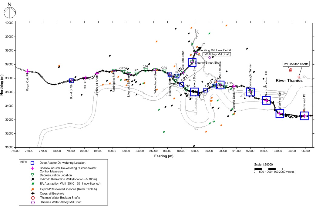
Figure 2 – Layout of Crossrail Tunnels in plan with location of dewatering and depressurisation works Boreholes were located so that they did not intersect the tunnelled sections or structures so as not to 1) provide a preferential flow path through groundwater installations into the works and 2) pose a risk to tunnelling personnel due to collapse of borehole infill. Table 1 below summarises the strategy at different structures.
Structure Type Borehole Spacing (m) Depth Closed face TBM tunnels Cable percussion (LCP) start to 20m (max) with Rotary follow on(1)
Deep borehole to base of current stratum
100-150m and distributed either side of the tunnel.
Every 500m
Minimum of 10m (approx. 1.5 tunnel diameter) below invert of deeper tunnel Shafts One deep borehole should be rotary to provide continuous core for logging and advanced effective stress testing. Second deep borehole for self-boring pressuremeter/ high pressure dilatometer/ self-boring permeameter depending upon ground conditions to provide stiffness and in situ stress profile.
Where possible Cable percussion borehole to below base of shaft to identify water strikes which are difficult to pick up in rotary holes drilled with flush
At least 3 equidistant around the shaft 2 of 3 to at least 15m below base of shaft Portal At least two boreholes should be rotary to provide continuous core for logging and advanced effective stress testing. At least two borehole for self-boring pressuremeter/ high pressure dilatometer/ self-boring permeameter depending upon ground conditions to provide stiffness and in situ stress profile. 100m max and distributed either side of portal Minimum of 10m below deepest part of structure i.e. below base of retaining walls. Cut and Cover box stations Minimum of four deeper holes by rotary techniques to provide continuous core for logging and advanced effective stress testing. At least two borehole for self-boring pressuremeter/ high pressure dilatometer/ self-boring permeameter depending upon ground conditions to provide stiffness and in situ stress profile. 100m to 150m around perimeter of station box 10m to 15m below base deepest part of structure i.e. below base of retaining walls Table 1 – Investigation strategy for each Crossrail structure type
Cable percussion boreholes were drilled through the superficial deposits with rotary techniques through the London Clay, the tunnel horizons and below. Additionally use of rotary techniques below 20m was found to reduce the risk of LCP casing jamming in the boreholes. Rotary techniques were always specified where the borehole penetrated more than 3m into the Chalk Group to allow good sampling of the Chalk.
Downhole and cross-hole seismic testing should be considered for shaft and station sites where there is ground variability e.g. Lambeth Group sand channels.
Self-boring pressuremeters and high pressure dilatometers were equipped with internal “feeler arms” to accurately measure the cavity expansion at several points in the test pocket to give accurate estimates of in-situ stiffness. The pressuremeters/ dilatometers also gave measurements of in situ stress. In situ stress and stiffness are key parameters in the design of retaining structures for shafts, portals and station boxes.
3 Groundwater monitoring
All boreholes had at least one groundwater installation installed within them, but typically had two installations “nested” in a borehole with a typical vertical separation of 10m bentonite backfill between each installation to ensure the integrity of the seal between them (ref [4]). The installations included primarily standpipe, gas standpipe and Casagrande standpipe, but also included piezopress, multilevel grouted vibrating wire, Waterra continuous multichannel tube (CMT) and Multiport sampling (Sol expert MPSS) systems. Field trials indicated that a minimum vertical separation that ensured hydraulic separation between piezometers was about 4m, of bentonite or cement-bentonite backfill. However, this required close, independent supervision of the installation contractor to ensure persistently high quality installations (ref [4]). Poor quality installations led to compromised instruments, and these were often only detected after months of monitoring, at very significant cost if new borehole access and mobilisation were required to replace the faulty installations.
Bespoke proprietorial systems such as the Waterra CMT system and the Sol Expert MPSS systems (Figure 3) allowed up to seven nested installations per borehole, each separated by a minimum of 4m of bentonite seal (ref [4]). The Waterra CMT system was most cost effective. The Sol Expert MPSS system was significantly more expensive, but permitted the carrying out of pumping tests or ground water sampling from any of the installations while monitoring the others (refs [4] to [7]). Grouted-in multi-level vibrating wire piezometers were also very cost effective and could cater for up to 3 installations per borehole. However, very careful specification and independent supervision of the installation and backfilling activities are essential to avoid vertical connectivity between the instruments by flow along the device cables as previously mentioned (refs [4] to [7]). Such connectivity would render the instruments unreliable. Figure 4 shows the very successful application of these systems at Stepney Green, and allowed the complex multi-aquifer pore water pressure profile to be determined and interpreted before tunnelling.
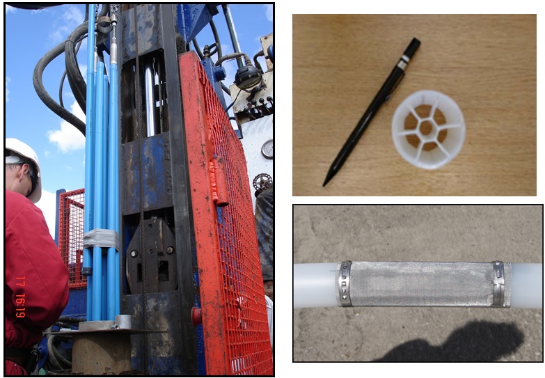
Figure 3 – (left) Sol Expert MPSS system of independent tubes, each with one piezometer and an associated independent response zone. Right, CMT-7 system with seven independent compartments produced as one continuous moulded tube. During installation, holes are made at different elevations to tap into each compartment and these are each associated with an independent response zone. The central tube monitors an installation at the base. 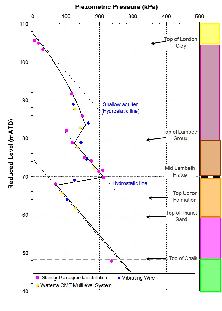
Figure 4 – Results of piezometer trials at Stepney Green, showing the successful performance of (i) the nested standard Casagrande standpipe, (ii) the grouted-in multiple-level vibrating wire system and (iii) the multi-level Waterra CMT-7 system. Note that the various systems very successfully provide a groundwater pressure profile through (i) the upper aquifer in the River Terrace Gravels above the London Clay, (ii) the drawndown pore pressure profile in the London Clay, (iii) the hydrostatic intermediate aquifer in the upper Lambeth Group which is rich in sand channels in this area, (iv) the Mid-Lambeth Hiatus which has a low vertical permeability and which sustains a large pore pressure differential between the intermediate aquifer in the upper Lambeth Group and lower aquifer in the Thanet Sand and Chalk, and (v) the hydrostatic pressure distribution in the deep aquifer. Groundwater monitoring requirements for the Crossrail piezometers varied according to the following strategy. The ground investigation contractor monitored the installations daily during fieldwork, weekly for four weeks following completion of all fieldwork and monthly for a further 12 months. Subsequently the instruments were monitored every 3 to 6 months in preparation for annual updates of the groundwater monitoring report (Figure 5 and ref [2]). During construction, monitoring responsibility was transferred to construction contractors as discussed in Sections 3 and 4.
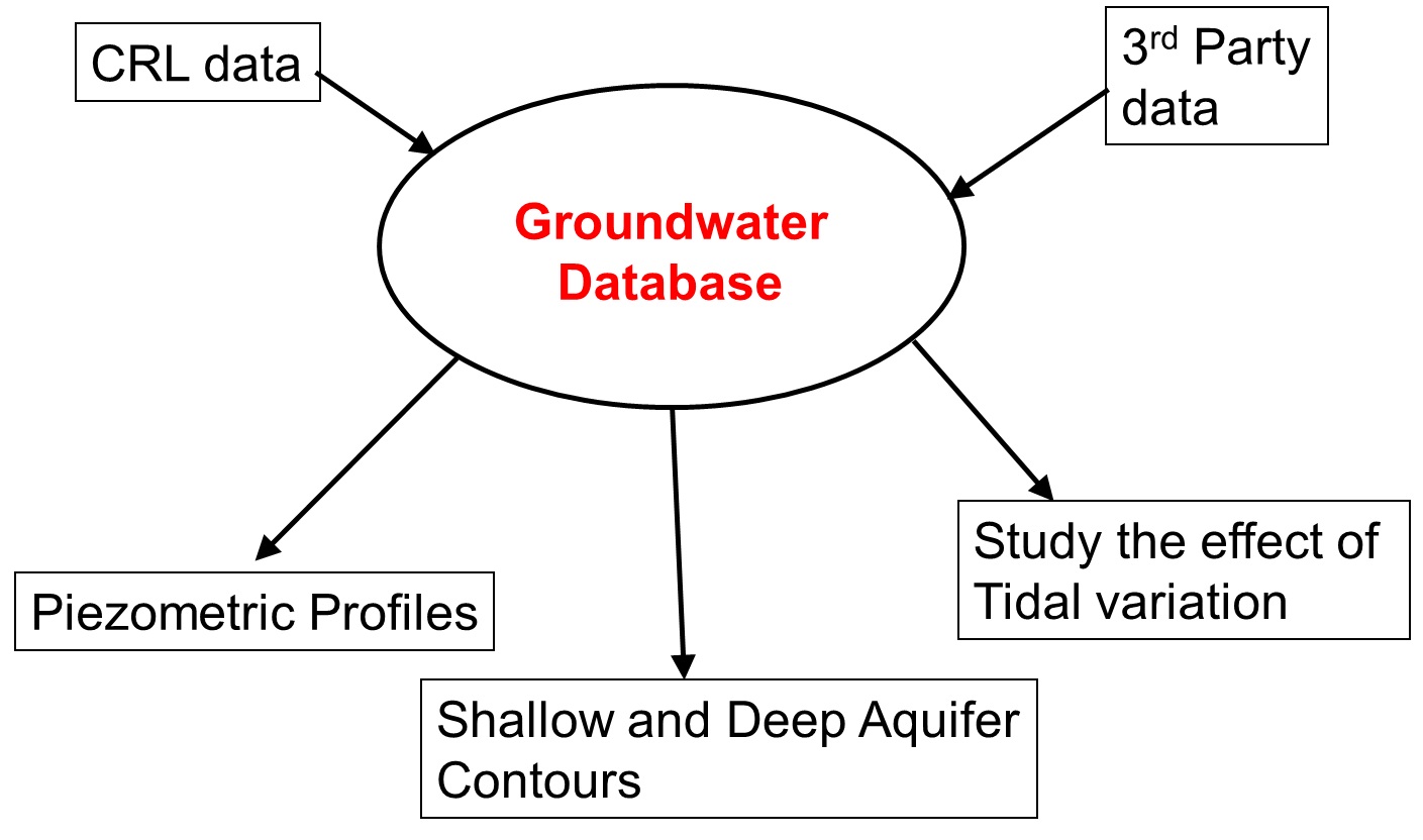
Figure 5 – Implementation of groundwater monitoring strategy The groundwater instruments were monitored in order to collect the following information:
- Determine pore pressure profiles for design of underground structures
- Determine pore pressures in granular/fissured strata that may require construction dewatering, depressurisation or other forms of ground treatment in order to maintain the stability of excavations.
- Determine pore pressures to assess the risk of base heave and/ or flotation
- Determine the extent of dewatering settlement effects
- Compile a baseline of natural water level fluctuations including tidal effects. These effects are very important for some construction activities such as control of TBM slurry pressure and design of dewatering/ recharge measures in such areas.
- Compile a baseline of groundwater quality measurements for the construction phase.
The instruments revealed an underdrained profile within the Lower London Clay Formation which extended into the underlying Lambeth Group. Pore pressures dropped to low values before increasing hydrostatically within the Chalk Group at depth (see Figure 4 for one detailed example and Figure 1 for distribution along the alignment. The depth range for the underdrainage was greatest in the west decreasing to the east due to historic pumping and deep aquifer drawdown in central London. The pre-tunnelling groundwater profile becomes fully hydrostatic from the surface in the area between Canary Wharf and River Lea where faulting (Greenwich Fault and Plaistow Graben) and folding (Greenwich Anticline) bring the Thanet Sand Formation and Chalk Group to the surface (see Figure 1).
Data collected from the Crossrail piezometers was combined with data from third parties, such as the Environment Agency (EA), London Underground Ltd, Thames Water and property developers who conducted their own ground investigation boreholes and shared data with Crossrail for mutual benefit (Figure 5). By far the largest and most regular source was from the EA. This large pool of groundwater information allowed the impacts of local and regional geological features on ground water to be discerned. As an example, the Greenwich Fault crosses the tunnel alignment near Connaught Tunnel and North Woolwich Portal and was seen to have no significant effect on horizontal groundwater flow. On the other hand, the East India Fault, just to the east of Canary Wharf Station, and the fault series at Farringdon Station had a significant effect on vertical pore pressure profiles either side of these faults (See Figure 1). Comparison between the water level readings along the route and the London Basin Groundwater model and third party data allowed the near-linear collection of readings for Crossrail to be put into their wider context.
Thus, through discussion with the EA regarding the London Basin Groundwater model, the Crossrail data allowed refinement of the position of impermeable faults in the area crossed by the project. Fault controlled groundwater flow can be a risk to structures during construction dewatering. Where a fault crosses a cone of drawdown, the fault can provide a constraint to water flow and effectively either truncate or significantly steepen the drawdown cone in the area of the fault. The general experience from Crossrail and the preceding Jubilee Line Tunnel Extension Project is that settlement induced by deep aquifer dewatering does not usually generate any significant damage to overlying structures. This is because the resulting settlement bowl is very flat and too low to induce damage[1]. However, where faulting may significantly affect the groundwater flow, induced settlements may be more variable and a more detailed assessment of dewatering induced settlements is warranted. Linear infrastructure which cross major fault zones are at risk of such potentially rapid changes in ground and groundwater conditions over short distances
3.1 Pre-construction Groundwater Monitoring
In 2009, approximately 1 year before construction commenced, one of the framework ground investigation contractors was instructed to carry out a co-ordinated monitoring regime in order to prepare for start of construction works. This included:
- The monitoring of licensed abstractions within the predicted drawdown cone of depression due to anticipated Crossrail dewatering. The drawdown cone was defined as being bounded by the 2m drawdown contour, with a drawdown of less than 2m being considered as insignificant given the historic changes in water level and the normal design practice of setting pumps for abstraction with a large headroom margin below current dynamic water levels (ref [8]).
- Remediation or replacement of damaged or unreliable piezometer installations.
The locations of all instruments were reviewed to ensure appropriate spatial coverage and coverage of all strata. Installation of piezometers for any identified gaps was instructed through ongoing ground investigations. Additionally installation of off-alignment “sentinel wells” was instructed. The Sentinel wells were positioned to monitor both groundwater level and groundwater chemistry at locations between Crossrail construction dewatering sites and known third party sites of contamination. The sources of contamination remained the responsibility of the third parties but any interaction between construction dewatering and these contamination “hotspots” could pose a risk to Crossrail – e.g.by remobilisation of the contamination. The sentinel wells could therefore give advanced warning of contaminant mobilisation before it had moved very far, and certainly well before it reached the Crossrail excavation works and abstraction wells. This would allow time to put in place mitigation measures and potentially prevent unplanned cessation of dewatering works, possibly at critical stages of construction. The Sentinel wells also provided off-alignment groundwater information that allowed the contours of groundwater level to be well conditioned and not to rely solely on measurements along the linear tunnel alignment.
Figure 2 shows the locations of Crossrail dewatering, as actually constructed, which accounts for ground conditions actually encountered. It distinguishes between minor depressurisation from permeable units of the Lambeth Group and dewatering sites where abstractions were made from the deep aquifer.
In the period running up to commencement of dewatering works, baseline readings were established using the following monitoring frequency, to augment data collected during the individual ground investigations. Installations along running tunnels were monitored at 3 monthly intervals. Installations around shafts, stations and portals were monitored at monthly intervals, unless the installations were in the London Clay then the readings were taken at 3 monthly intervals.
Individual construction contractors mobilised and developed their dewatering plans, which are temporary works and so the responsibility of each contractor. As this occurred, monitoring of piezometers within the area of influence of each contractor’s dewatering works was handed over to the individual contractors. For a large project like Crossrail, this required careful management by the Owner/ Promoter’s Team to ensure smooth handovers without overlap but with adequate coverage of interface areas. In preparation for each construction contract a handover document was prepared detailing each of the instruments within the principal contractor’s sites. The contractor was instructed to review the distribution of the instruments, adopt those required to demonstrate the performance of the contractor’s works and decommission the remainder.
4 Long Term performance
During the construction works, Crossrail continued to centrally collate and interpret all the groundwater level and water quality information from the respective contractors and some third parties using a similar process to that illustrated in Figure 5. In such a large project with many contractors at different stages of construction, each developing and modifying their temporary works dewatering plans to suit their own needs, this required careful liaison and interaction by the Crossrail Client Team with the various contractors.
This enabled Crossrail as the Owner/ Promoter, with oversight of the whole process, to meet its legal obligations under the Hybrid Bill. These obligations are encapsulated in the Environmental Impact Statement (EIS) and require the project to not cause significant impact by its dewatering works or else to suitably mitigate any such effects. Demonstration on site that Crossrail always met these obligations was by the production of monthly reports of the measured dewatering performance across the whole Crossrail Project and its impact. As well as regional water levels, these reports contained information on the rates of abstraction, discharge arrangements, water quality monitoring and any necessary treatment that was required. The reports were produced by the Crossrail Client Team for the EA (e.g. ref [9]). This was also coupled with a monthly liaison meeting with the EA where any issues were discussed.
Figure 6 shows the predicted abstraction flow rates for the Crossrail Project. It depicts the initial predictions in the EIS, the modified predictions after the project cost envelope was reduced, as announced in the Government Spending Review of autumn 2010. This necessitated a revised and extended programme. Also shown are the actual measured abstraction rates during the project. In general, abstraction rates were well below the predictions until dewatering at CP13. Flow rates at CP13 proved to be much larger than anticipated. By careful dewatering implementation and monitoring, and use of grouting and ground improvement techniques, dewatering was undertaken without derogation of licenced abstractors and without any significant impact.
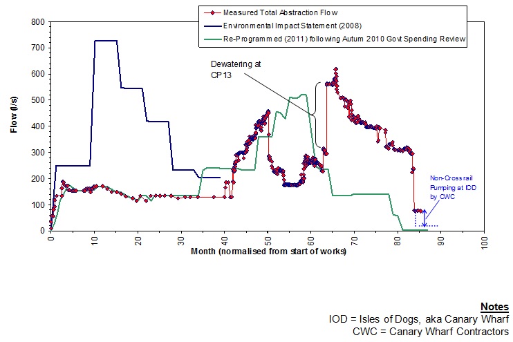
Figure 6 – Deep Aquifer Construction Dewatering Abstraction for the Crossrail Project. On completion of the civil construction works, the contractors were required to monitor for a period of time after cessation of dewatering activities. This period varied from site to site and was dependent upon the extent of groundwater drawdown and the rate of recovery, but was typically 3 to 6 months. At the time of writing, Crossrail dewatering is essentially complete, although there are still some limited dewatering activities ongoing at Limmo and local depressurisation in other areas for specific elements of construction work. The frequency of readings taken during the recovery phase was similarly dependent upon the rate of recovery and was specified on a site by site basis. This may be daily in the early stages when recovery was rapid reducing to weekly or less as the rate of recovery reduced. Diver loggers, which are miniaturised data loggers that are small enough to fit into the 28mm diameter tube of Casagrande piezometers proved very useful for the monitoring process (ref [10]). These divers are compact and self-powered and could log at a regular frequency, retaining the data obtained until downloaded. They are installed by suspending the divers at a known depth below the water level in the piezometer. Visits by a monitoring technician could therefore occur at convenient intervals for data recovery and analyses, which were much longer than the recording interval following the dewatering works. Divers need to be installed at a level below the anticipated draw down during the various stages of the dewatering works. Where this is not known or changes, additional visit to lower the divers may be necessary if the water levels fall below the diver’s elevation, which can be inferred by interpretation of the data.
On completion of all works, the piezometers and any remaining wells were decommissioned. Crossrail provided the contractors with Environment Agency guidance on how these piezometers and wells should be sealed (ref [11]). The necessity to adequately seal the instruments was more critical for deeper instruments, where a physical link from the near surface to the deep aquifer (the Principal aquifer) needed to be sealed to eliminate the risk of contamination.
5 Conclusions
The Crossrail project is a new underground railway crossing London from west to east and involving substantial tunnelling works. A carefully scoped series of ground investigations for the revised alignment (that was eventually constructed) involved the installation of some 800 piezometers. These allowed accurate determination of the groundwater regime across the tunnelled section and its temporal and spatial variations. Groundwater information was important to inform the design, and for the construction phase, to facilitate safe and good quality construction, and to demonstrate and ensure that construction effects on third parties were as predicted and if necessary suitably mitigated.
Piezometric installations were optimised by using multiple installations in a borehole where feasible. Systems allowing the installation of up to 7 piezometers in one boring were trialled and proven before roll-out across the project. The systems that were used are described in this paper and allowed detailed characterisation of complex aquifer systems before tunnelling and during construction works. It was found that the Waterra CMT system was the most cost effective, per piezometer, but that the standard Casagrade standpipe piezometer and the grouted-in vibrating wire piezometers were also cost effective when compared against the alternative of several separate installations. The Sol Expert MPSS system was significantly more expensive, but permitted the carrying out of pumping tests or ground water sampling from any of the individual installations in the multiple-array instrument. This configuration could be very effective for testing multi aquifer conditions. Very careful specification and supervision of the installation and backfilling activities are generally required for multi-level piezometers, but particularly so for multi-level grouted-in piezometers. These checks are essential to avoid vertical connectivity between the instruments which would render them unreliable. Given that the cost of remobilisation and replacement of such instruments is significant, and that failure of the instruments may not be obvious until after months of monitoring, such precautions seem worthwhile.
Groundwater monitoring was carefully managed by the Crossrail Client Team, with oversight of monitoring which was undertaken by a range of contractors, from ground investigation contractors at initial stages to large construction contractors during construction. This proved a necessary and successful model to obtain the required data, maintain oversight of the differing and changing works, and retain a continuous and reliable line of reporting to the EA. In combination with the monthly liaison meeting with the EA, it allowed Crossrail as the Owner/ Promoter to demonstrate that all its statutory obligations relating to dewatering and its impact were met.
Baseline monitoring for the construction dewatering works commenced about one year before the onset of dewatering and involved monitoring of both groundwater level and quality at a frequency of one reading every 1 to 3 months, combined with existing information from the various ground investigation packages. A higher frequency of monitoring was implemented during construction, often using miniaturised diver loggers recording groundwater levels at 10 to 30 minute intervals, but downloaded at more convenient intervals. On completion of the civil construction works, post dewatering monitoring was conducted over a period that varied from site to site, but was typically 3 to 6 months, at a reducing frequency.
At the time of writing, Crossrail dewatering works is essentially complete and there has been no significant impact on the deep aquifer. There has also been no significant impact on licenced abstractors. With the near completion of the dewatering works, attention has switched to decommissioning the piezometers and wells in accordance with the Environment Agency guidance. This is primary to minimise the risk of contamination of the deep aquifer via these installations.
References
[1] GCG (2006) “Crossrail, Re-scoping of Ground Investigations for Crossrail Line 1”, Document 1D0101-G0G00-00518, Rev A dated July 2006.
[2] GCG (2009) “Crossrail; Groundwater Monitoring Strategy”, Document 1D0101-G0G00-00571 Rev B, dated Sept 2009.
[3] GCG (2012) “Crossrail, Interpretation of Remedial Works for Crossrail Piezometers”, Document CRL-GCG-C2-RSI-CRG03-00001 Rev 1 dated 24/5/2015.
[4] GCG (2009) “Crossrail, Multi-level Piezometer Trial at Stepney Green: Evaluation and Interpretation of 3 Systems”, Document 1D0101-G0G00-00548, Rev A dated Feb 2009
[5] GCG (2007) “Crossrail, Multi-Level Piezometer Trial at Stepney Green: SolExpert Multi Port Sampling System”, Report 1D0101-G0G00-00547 Rev A
[6] GCG (2007) “Crossrail, Multi-level Piezometer Trial at Stepney Green: Vibrating wire Sensors in Grouted Borehole”, Report 1D0101-G0G00-00546 Rev A.
[7] GCG (2007) “Crossrail, Multi-level Piezometer Trial at Stepney Green: Solinst Continuous Multichannel Tubing CMT-7”, Report 1D0101-G0G00-00545 Rev A.
[8] Mott MacDonald (2008) “Cross London Rail Links Ltd, Planning and Environment Mitigation for Well Owners”, Rev04 dated 20/10/2008. Document No. CR-PN-PRW-CN-RT-00001
[9] GCG (2015) “Crossrail, Monitoring of Construction De-Watering – December 2014”, Document Number: CRL1-GCG-C2-RAN-CRG03-00001, Rev 37 dated 15/1/2015.
[10] Information on Diver loggers http://diver-water-level-logger.com/en/diver-water-level-loggers/
[11] Environment Agency (2012) “Good practice for decommissioning redundant boreholes and wells”, dated October 2012 http://webarchive.nationalarchives.gov.uk/20140328084622/http:/cdn.environment-agency.gov.uk/LIT_6478_8cbe6f.pdf
[1] The exception to this general observation is where the shallow and deep aquifers are connected and settlement of the deep aquifer is allowed to cause settlement of the Made Ground or Peat overlying the upper aquifer. Another exception is when the overlying structure or asset is founded on complex foundations, some of which are shallow while others are deep. More careful assessment of dewatering induced settlements is warranted in these cases.
-
Authors

Dr Ursula Lawrence PhD Eur.Geol C.Geol FGS C.Sci - Crossrail Ltd
Geotechnical Engineer, Crossrail
Chris Menkiti - Geotechnical Consulting Group
Geotechnical Consulting Group

Mike Black BSc(Hons) MSc CSci CGeol FGS - Crossrail Ltd
Mike is the Head of Geotechnics within Crossrail’s Chief Engineer’s Group. Mike’s role is to provide technical and professional leadership for all geotechnical aspects for the tunnelling and civil engineering sub-surface infrastructure work. He has been on the Crossrail Project since 1993 and has been involved in all stages of development of Crossrail from feasibility design, through the Parliamentary Bill process, ground investigations, civil design and construction. Prior to joining Crossrail, Mike worked in the oil and gas industry in the North Sea, the Channel Tunnel, the A27 Brighton & Hove Bypass and the Jubilee Line Extension.
https://www.linkedin.com/in/mike-black-4aa9b81b?trk=hp-identity-name
