The Crossrail Requirements for the Emergency Power Supplies (Uninterruptible Power Systems)
Document
type: Technical Paper
Author:
Paul Kerrigan BEng CEng MIET
Publication
Date: 02/12/2021
-
Read the full document
Introduction
A total loss of power to all or any of the critical plant locations across the Elizabeth line would lead to the inability to continue to run the rail network safely and effectively. The life safety critical power supplies that require an uninterrupted power supply are:
- Emergency Lighting
a. Station Evacuation Lighting.
b. Tunnel Evacuation Lighting.
- Critical Communication systems
a. Signalling
b. Public Address and Voice Announcements.
Uninterrupted Power Supply Solution
Following the clear identification of the critical load equipment, and the relevance to life safety and a safe evacuation of the railway, the decision to use a UPS to protect against power supply failure is overwhelming.
System Topology
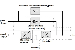
The two main choices of system type here are off-line or on-line, The difference between the two systems is that the on-line UPS supplies power from the AC mains to the Load through the rectifier and inverter combination while the off-line UPS directly supplies power from AC mains to the load, see Figure 1. The chosen system to meet the Elizabeth line requirements was an on-line system as the on-line UPS is a type of UPS that supplies power to the AC load through the rectifier and inverter in normal operation and uses an inverter to supply AC power during a power failure. Therefore, the output power supply always stays ON and there is no need for manual switching in the event of loss of supply. Hence, there is no time delay in switching between its sources. There is no interruption in the case of power failure providing an even transition of supply.
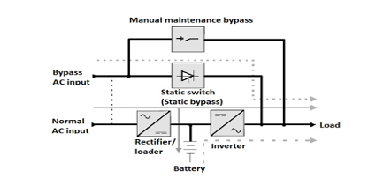
Figure 1.
Operational Principles of the On-Line UPS
When the mains supply is present this block float charges the battery and supplies the inverter with a regulated dc voltage. In the absence of the mains supply the charger shuts down and the inverter dc supply is provided by the battery, which begins to discharge. The dc power connection between the rectifier/battery and inverter is often known as the dc busbar, or dc bus.
As part of its control function the rectifier/charger generally includes an input current limit feature to provide overload protection, and a dc overvoltage shutdown mechanism to provide the battery/inverter and dc filter components.
This UPS design is sometimes referred to as a double conversion UPS, due to its two conversion stages of AC-DC and DC-AC and offers the greatest degree of critical supply integrity in that the load is always supplied with processed power. That is, when the UPS input mains supply is present the rectifier, charger and inverter power blocks are all active and the load is connected to the inverter output. As the load is powered from the inverter under normal circumstances it is supplied with a well-regulated voltage and protected from input supply aberrations because the rectifier and inverter act as a barrier to mains-borne noise and transient voltage excursions.
If the input supply goes outside a pre-set voltage range (typically +10% to -20%) or frequency, or suffers a total failure, the inverter continues operating from battery power and the event is totally transparent to the load as there is no transfer operations involved. When operating from battery power the inverter supplies the same degree of supply regulation as when the mains is present. If the mains is not restored before the battery reaches its end-of-discharge voltage the inverter shuts down resulting in a total loss of load power.
Systemwide UPS Architecture
The Crossrail project utilised a common component framework supplier for all the UPS systems on the project. At each station location the UPS systems were divided into two separate autonomous systems; one dedicated to emergency lighting and the other to essential communication systems. At each of the 8 station locations* the UPS systems are configured to best support the LV and communication distribution, therefore generally there is 1 emergency lighting UPS and 1 communication UPS located in the east section of the station and this is duplicated in the west of the station, each system has a dedicated room.
*(Exceptions are):
-
- Liverpool St station that has a total of 6 autonomous systems.
- Whitechapel Station that has 5 autonomous systems
- Custom House Station has only 2 autonomous systems
UPS Supply characteristics
The UPS is connected such that if both A and B supply fail, the batteries would support the load. However, if either A, or B were to fail (not both) the UPS will not transfer to the battery supply and continue off the A or B supply. The battery source is only used when both A & B supplies to the UPS system have failed. The supply is normally fed by inverter circuit to ensure load is fed from conditioned supply. An Automatic Transfer Switch (ATS) is installed for transition between supply sources. The communications UPS provides a line conditioned supply through the UPS whether being fed from source A, B or batteries. The UPS only goes to bypass in event of overload, fault, or manual intervention. The system was designed with a 25% spare capacity margin against each verified load schedule.
System Design and Characteristics
The online UPS system includes an external maintenance “wrap around” bypass switch enabling UPS system to be electrically isolated and taken out of the critical power circuit, allowing for safe UPS maintenance, service work, or unit replacement without any disruption to the load.
Without the inclusion of the external bypass switch, preventive maintenance opportunities, to the system would not be feasible without powering down the entire critical load supported by the UPS system.
The external bypass switch also incorporates mechanical interlocks, known as Castell keys, this ensures the bypass operates in the correct sequence and doesn’t damage the UPS or the load when operated. Figure 2 shows Normal Mode, Figure 3 Bypass Mode and Figure 4 Mains Failure. The Supported load Autonomy for the emergency lighting UPS systems was 3 hours and for the Communication systems 4 hours. A further requirement was the capability of UPS Systems to recharge the batteries to 80% capacity in 8 hours and to 95% capacity in a further 12 hours, specifically to ensure following a power outage any location could be fully operational again within an eight-hour time frame.
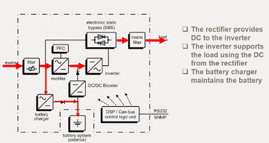
Figure 2. Normal Mode
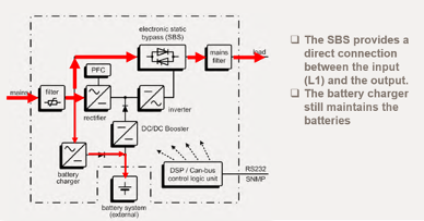
Figure 3. Bypass Mode
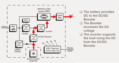
Figure 4. Mains Failure
Short circuit clearance
The UPS reaction to a short-circuit in downstream distribution on the output side would result in, the load impedance depleting to practically zero. Under these circumstances the UPS output voltage collapses since the inverter cannot provide infinite current to maintain a proper voltage at system output. The UPS will try to secure continuous power for the load and will transfer immediately to static bypass. This functionality, or the actual transfer sequence, is described as “emergency transfer to bypass”. The UPS reacts by “assuming the worst case” and will maximise the fault clearing energy to clear a fault in UPS system output as quickly as possible, thus minimising the impact for the critical loads. The bypass feed can provide considerably more current to clear a fault, compared to an inverter current limit. Once the fault is cleared, the UPS will transfer back to normal mode automatically.
In the bypass mode the fault current is limited by line impedance and the UPS static switch capabilities only. If eventually the inverter cannot clear a fault and restore normal voltage to output, the UPS will transfer to bypass after a few hundred milliseconds. The risk is that a prolonged interruption in system output voltage will impact the critical loads.
The LV and UPS system design under a downstream short-circuit condition is important, and therefore equipment selection is critical. Whenever the UPS bypass feed is not available, and fault occurs at UPS system output, the UPS will use the inverter to clear the fault. In this case the inverter will feed as much current as it can, until the fault has cleared, and system voltage restored. If the inverter cannot clear the fault, it will shut down after a internal timer has expired. In this case the UPS system is turned off and power to the load would be interrupted.
The Elizabeth line UPS systems are designed to trip a maximum of a 32amp type C MCB, (the largest downstream MCB) using battery power on a faulty downstream LV circuit, thus preventing emergency transfer to bypass.
Maintenance Utilising the Q2 Neutral Switch
The Elizabeth line UPS does not have isolating transformers on the input supply point, the consequence of this was that it was identified under certain unique maintenance conditions such as replacement of critical switch boards a potential hazard to the UPS equipment existed, when the neutral connection from the supply switch board to the UPS is removed and the voltage on the output side of the UPS will ‘float’, i.e., it will not be tied down to reference Earth. Therefore, it is an unsafe condition for personnel and equipment and is not permitted under BS7671.
The solution consisted of the design and installation of a ‘Q2’ neutral switch for each UPS unit, this also included a process for the removal of solid bolted neutral links The Q2 switch has 3 operating positions. Figure 5 shows the normal position of the Q2 neutral switch taking a neutral reference point from switch board B. The further switch positions allow for the isolation of either switch board A or B while still achieving a neutral reference point from the alternative supply (Figure 6). A Crossrail technical paper titled, ‘UPS Neutral Switch Arrangement Technical Paper’ (CRL1-XRL-E-RGNCR001-50010) was written detailing the specific cause and effect scenarios and detailing the operational switching procedures.
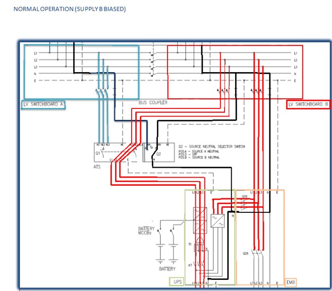
Figure 5. Normal operation (Supply B Biased)
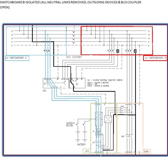
Figure 6. Switch board B isolated (all neutral links removed, outgoing devices and bus coupler open)
Battery Fuel Cell Configuration
The battery fuel cells on the project are of the value regulated lead acid type (flame retardant UL 94 class VO) and were configured as a ‘parallel’ string comprising of identical serial strings connected in parallel across the UPS battery input. The typical configuration would have two serial strings, comprises of 2 parallel strings of 64 cell blocks. Each battery string is protected via a dedicated Battery MCCB. The design load from this configuration would be 31.2kVA (28.0kW) for 180 minutes capacity. A parallel arrangement provides longer battery autonomy during a mains failure. Additionally, resilience is created because a single battery failure will not totally deprive the load of battery backup.
The battery cells are housed generally in separated temperature-controlled rooms and sit on open racks to maximum air flow and cooling, the optimum temperature for longevity of battery life is 20 degrees Celsius. The design life of the batteries is 10 years.
The battery recharge process deploys a two-tier battery charging regime. These are FLOAT charge and BOOST charge cycles. Float charge is the normal mode of battery charging, but when the mains to UPS rectifier fails causing the battery to discharge, on mains return, the UPS rectifier automatically begins a timed boost charging of the battery for a period up to 20 hours. Boost charge comprises of recharging the battery at an elevated voltage (the boost charge voltage). The boost charge voltage enables more current to be driven into the battery and thereby achieve a faster battery recharge. Valve regulated lead acid batteries create hydrogen when reaching an overcharge state, which is approximately equal to => that 80% charge capacity. So, during normal UPS operation with the batteries in standby, they evolve hydrogen, hydrogen evolution increases during boost charge period, particularly if the battery reaches its overcharge phase, the Battery rooms are suitably ventilated to dissipate any hydrogen gas.
Battery Sizing Calculations
The considerations when undertaking battery capacity sizing, are simple parameters and factors such as:
- The system loads (KW)
- The required Autonomy
- Life expectancy / Ageing factor
- Battery load allowing for UPS inverter efficiency (KW)
- Battery manufacturers power over discharge duration
- Cell configuration and denomination
Generally, as the Elizabeth line batteries have a whole life expectance of 10 years an aging factor of 1.25 multiplied by the load value.
A typical manufacturers battery data sheet would be as in Figure 7.

Figure 7. Battery data sheet
Recommendations for Future Projects
Considerations should be given to the design life of the batteries. 5 years is generally the industry expectation. By extending the battery life to 10 years as is the case on the Crossrail project, this increased the quantity of batteries required and impacts upon the overall system whole life cost with limited added benefit.
The importance of making correct choices between 3- and 4-pole input switching is critical, as they have consequences for safety and regulatory compliance. The Crossrail project resolved this issue with the adoption of the Q2 switch which added to the complexity of maintenances procedures.
The UPS selection and location is critical in striking the right balance between availability, safety, resilience, and cost of the power distribution system, especially where UPSs are involved. This becomes a complex calculation – and one that is liable to continued change as the critical load grows. With these considerations in mind, early involvement, and engagement with UPS specialists is critical to ensure a successfully outcome.
Conclusion
The critical life safety power systems line wide serving the Crossrail Project are robust with ALARP resilience. The UPS selection and design evolved as the LV load schedules evolved. A UPS solution was the only practicable approach as consideration had to be given to the location of the equipment generally located in a subsurface environment.
The interaction between the UPS and LV power distribution can cause issues that are not allowed for when considering either LV power distribution or UPS systems alone. These issues can create risks for safety and reliability. This interaction is complicated by the fact that it changes according to the operating mode of the UPS – normal, battery or bypass. In all cases, behaviour during nominal current, overcurrent and short-circuit current conditions must be considered. Available short-circuit current also depends on how the system is used. The importance of making correct equipment choices at the design stage are critical to compliance, safety, and budget.
References
[1] F943 – Uninterruptible Power Supply Systems – Performance Specification F943 – XRL–E–RSP–CRG03–50001 – Crossrail Ltd.
[2] JV32 Uninterruptible Power Supply Crossrail M & W Specification – CRL-1-XRL-M-RSP-CR001-50043 – Crossrail Ltd.
[3] UPS Neutral Switch Arrangement CRL1-XRL-E-RGN-CR001-50010 – Crossrail Ltd.
[4] CRL1-CEC-00508 – Q2 UPS Neutral Source Selector Switch Operation and Identification – Crossrail Ltd.
-
Authors

Paul Kerrigan BEng CEng MIET - Crossrail Ltd
Paul is Crossrail Lighting and UPS Engineer. He has worked on the project for 10 years with key responsibilities for developing lighting, UPS systems and LV Electrical Systems within all stations, shafts and portals throughout the project.