How Will Rooms Operate on Loss of Mains Power?
Document
type: Technical Paper
Author:
Matthew David BSc CEng MIMechE MCIBSE, ICE Publishing
Publication
Date: 30/09/2017
-
Read the full document
1 Introduction
1.1 Purpose
The purpose of this technical paper is to describe the rationale and the evidence used to assess whether the Heating, Ventilating and Air Conditioning, HVAC, Uninterruptable Power Supply, UPS, Systems should be omitted from all of the Stations, Shafts and Portals.
This paper discusses the resilience of the two independent Crossrail electrical power supplies (A & B) and the requirements for a supplementary Uninterruptible Power Supply, UPS, system to provide additional power backup to HVAC systems to serve various critical equipment rooms.The outcome of the report is to establish whether there is a need for an HVAC UPS based on the probability of failure of the A & B power supply, maximum room operating temperatures and room construction.
The failure of both A & B power supplies is referred to as a Critical Occurrence throughout this report.1.2 Crossrail Programme Functional Requirements, CPFR
The CPFR has the following requirements with reference to UPS systems and functionality in a Critical Occurrence.
1.2.1 For Stations
The following requirements were applied to Crossrail:
Each Central Operating Section station shall be equipped with centralised UPS facilities to provide continuous, regulated power to all essential services in the event of mains power failure. Stations shall be duel fed with each transformer serving the station lights being capable of taking a feed from one of two separate sources. In the event that one feed fails, the station can remain open, provided that there is a UPS whose integrity can be proven, and which has the capability of lighting the station under evacuation arrangements for at least one hour. This accords with current LU practice.
• The duration of the backup to each system shall be determined by the criticality and function of the system.
• The need for UPS on the stations shall be determined using a risk-based approach.1.2.2 For Shafts
The following requirements were applied to Crossrail:
- In the case of a power failure UPS shall be provided to ensure an adequate level of emergency lighting and essential communications facilities including Fire Alarm system.
- The duration of the backup to each system shall be determined by the criticality and function of the system.
1.3 Electrical Supply
The electrical power supply to each Station, Shaft and Portal is via two independent supplies from two separate connections, designated A&B, to the UK power supply grid network.
A schematic of the system is shown in Figure 1.
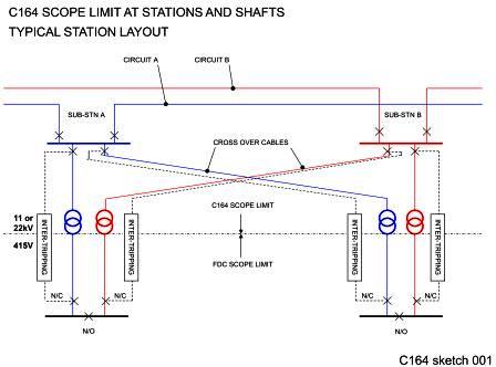
Figure 1 – Power Supply Network Schematic
These non-traction power supplies are independent of those feeding the track and rail system.
Each supply is taken to a distribution board in a dedicated room.There are two supplies, A and B, from each of the two connections. The A and B supplies run via separate routes through each facility to a dedicated distribution board. Both A and B are sized for 100% of the design maximum demand.
This power supply arrangement is extremely robust. The reliability of the power supply has been assessed with an Employer Reliability Availability Maintainability, RAM, analysis[1].
The conclusion from this report is as follows:“7 Conclusion of RAM Analysis
The non traction HV system reference design has been evaluated in terms of the availability of the 22 kV and 11 kV non traction HV system. The simulation results demonstrate that the proposed design will achieve a high level of availability.
Considering the limitations, the analysis is useful as a comparison of RAM performance with future design options and serves as a basis for future performance targets and equipment selection.A failure of either A or B supplies would then be supported from B or A as necessary. At any individual location, only a major incident, .e.g. a large fire, would disrupt the distribution systems of both A and B together. A loss of supply of the whole CRL power supply network would occur only with a large scale London or region-wide power outage.
Nevertheless UPS units were designed to each facility to support communications and signalling equipment, lighting and any HVAC support should the electrical power supply fail.
A single fire in a single compartment would not be sufficient to fail both the A&B supplies.1.4 The UPS
The UPS systems are required to operate in the event of a total loss of A & B electrical power supply, here called a Critical Occurrence, and support the following systems:
- Emergency Lighting Systems to maintain an autonomy of supply for 3 hours.
- Critical Communications Equipment to maintain an autonomy of supply for 4 hours.
- HVAC systems serving Critical Equipment Rooms to maintain an autonomy of supply for 4 hours.
There is no specific requirement for separate UPS systems. The standards governing Emergency Lighting UPS do allow other equipment to be served from the same UPS, provided that it is also associated with Life Safety systems and functions.
The Communications Systems Contractors do recommend that HVAC equipment is not added to the Communications UPS, due to power quality and reliability concerns.
These systems comprise:
1. A static inverter/rectifier unit, which converts alternating current to direct current and back again as required. Figure 2 is a typical example.
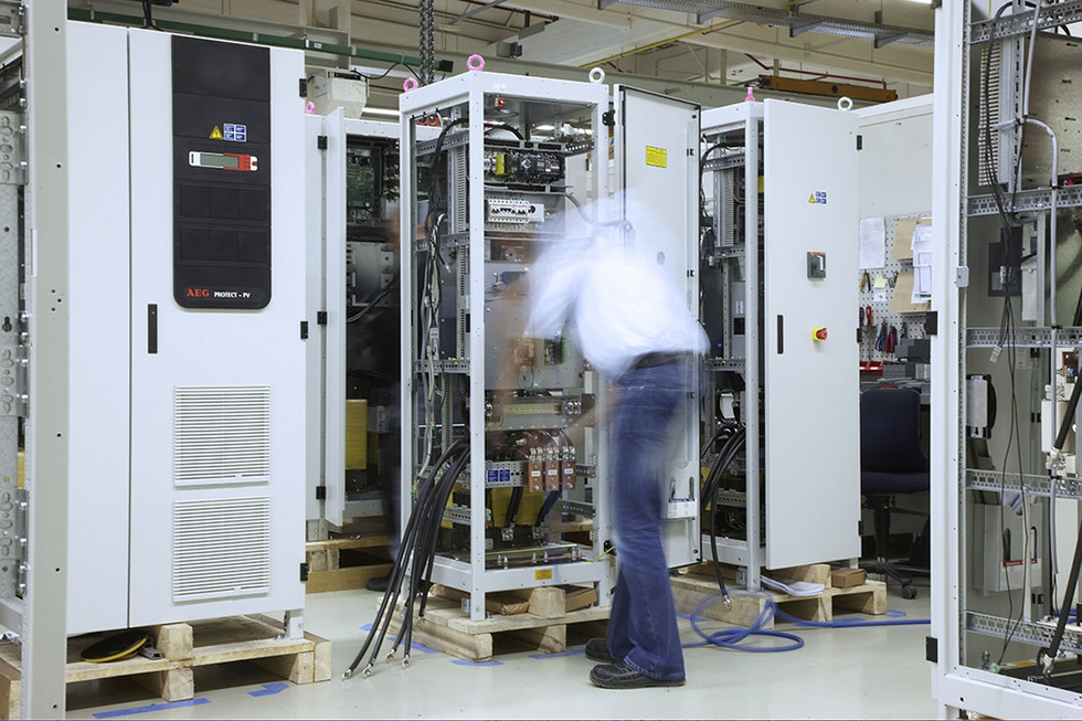
Figure 2 – Typical UPS Inverter Assembly
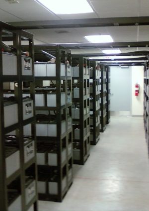
2. A set of batteries which hold the design electrical charge for the autonomous period. Figure 3 is a typical example of a battery rack installation.
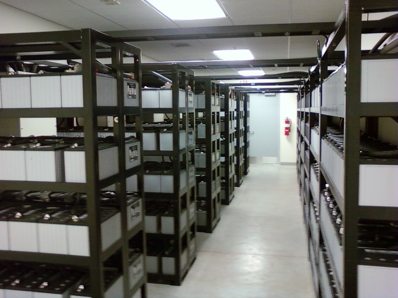
Figure 3 – Typical Battery Rack Installation
The critical Communication equipment includes servers and their associated equipment for:
- Radio
- Public Address system (PA/VA)
- CCTV
- SCADA
- Telephony
In the event of a Critical Occurrence the Comms UPS is required to support the following systems:
- Evacuation of the public and staff from the affected Station, Shaft or Portal.
- Enable the emergency services and staff to sweep through the facilities to check that evacuation has been completed.
- To provide support to the Comms and Signalling functions for the railway.
In such an event the railway will cease operation.
The design of the facilities is based on a single failure incident and not multiple simultaneous occurrences. The electrical support of Emergency Lighting and Communications systems in ‘life safety situations’, in the event of loss of normal power, is demanded by Standards.
There are other UPS systems:
- Signalling UPS in the SES-R
- Lift UPS in the Lift Equipment Room (LER)
- Additional UPS loads are the OHLE traction power circuit-breakers & tunnel vent system (TVS) damper control panel Programmable Logic Controllers, PLCs. These are not supplied via the HVAC UPS and therefore are not affected by its omission.
2 Critical Equipment Rooms
2.1 Rooms
The critical equipment rooms that require to be maintained in operation are:
- BAT – Battery Room
- UPS – Uninterruptible Power Supply (Batteries and inverter/rectifier)
- ESR – Emergency Switch Room (Inverter/rectifier only when batteries are in a separate room).
- CER – Communication Equipment Room
- SOR – Station Operations Room
- SER – Signalling Equipment Room (Communications equipment for signalling)
- SES-R – Signalling Electrical Supply Room (UPS and batteries to support signaling equipment)
- LER – Lift Equipment Room
These rooms are arranged differently and are of different character across the different locations. These differences are:
- Room dimensions.
- Room configurations.
- Adjacent spaces: ventilated enclosed rooms, unventilated enclosed room, cooled rooms, non-conditioned rooms, ground of differing materials and depths.
- Equipment heat output
- Room wall, slab and soffit construction with and without insulation.
2.2 Room Conditions
The following room conditions apply:
2.2.1 BAT
The batteries are designed to satisfy the UPS load requirements.
Batteries operate optimally at 20oC. At lower temperatures the charge capacity reduces but the reduction is small down to 15oC. At higher temperatures the service life decreases with a reduction of half the life for every 10oC above 20oC. In practice it is unnecessary to keep the room at a fixed temperature throughout the year. They could normally be allowed to fluctuate between 15oC and 27oC. In a Critical Occurrence the room temperature could be allowed to rise to 40oC and more without loss of charge capacity. Their life to maintenance would be reduced but the reduction would depend on how long the room remains at 40oC.
Batteries give off heat particularly on discharge. As an example the heat load for a 51 kVA battery is 450 W.
Summary:
Normal Operating temperature: 15oC – 27oC DB
Maximum Operating Temperature: 40oC DB but would still operate at up to 50oC DB and higher.2.2.2 UPS
re designed to provide rectification of their design electrical capacity over a wide range of temperature, from 0oC to 40oC. The environment in which they operate affects their working life but their ability to meet their stated electrical capacity is not affected.
UPS equipment is designed to switch off the inverter upon an over temperature condition occurring within the unit.Under normal operating conditions the room temperature could be allowed to fluctuate between 15oC and 27oC.
As an example the heat load of a 51 kVA UPS could be 7.4 kW in the worst case operating mode.
Summary:
Normal Operating temperature: 15oC – 27oC DB
Maximum Operating Temperature: 40oC DB but would still operate at up to 55oC DB.2.2.3 ESR
The requirements for this room are as for the UPS or Battery Rooms, whichever applies and is most onerous.
2.2.4 CER
The actual heat loads are likely to be approximately 20% of those stated in the early stages design.
This reduction can be illustrated by the CCTV cameras which have PoE (Power over Ethernet) where they are within 90m from the CER. This power would originate in the CER cabinets but only appear as heat at the cameras.
Also the quiescent power loading of the PA system is approximately 3% of its “broadcasting” loading which is the peak load stated. PA/VA broadcasts are intermittent so actual power loading and heat rejection is much less. A ‘broadcast’ profile should be produced. Without this a constant load is to be assumed.
The maximum permitted room temp is 40oC. This equates to a communications cabinet internal temperature of 60oC.
Under normal operating conditions the room temperature could be allowed to fluctuate between 15oC and 27oC.
Summary:
Normal Operating temperature: 15oC – 27oC DB
Maximum Operating Temperature: 40oC DB2.2.5 SOR
In a Critical Occurrence staff will direct the evacuation from this room. Certain functions, those not supported by UPS, will cease to operate. The staff will have the ability to open doors should the temperature rise.
Under normal operating conditions the room temperature could be allowed to fluctuate between 19oC and 24oC.
Summary:
Normal Operating temperature: 19oC – 24oC DB
Maximum Operating Temperature: 40oC DB2.2.6 SER
The railway will stop operating in a Critical Occurrence. The signal system will be required to set, monitor and record the final condition of the signals.
These rooms are very similar to the CERs with heat gains being much less than the cabinet power input.
Under normal operating conditions the room temperature could be allowed to fluctuate between 15oC and 27oC.
Summary:
Normal Operating temperature: 15oC – 27oC DB
Maximum Operating Temperature: 40oC DB2.2.7 SES-R
Under normal operating conditions the room temperature could be allowed to fluctuate between 15oC and 27oC.
Summary:
Normal Operating temperature: 15oC – 27oC DB
Maximum Operating Temperature: 40oC DB2.2.8 LER
An UPS is provided to power the lift to a floor of evacuation and for the use of the fire brigade.
Under normal operating conditions the room temperature could be allowed to fluctuate between 5oC and 25oC.Summary:
Normal Operating temperature: 5oC – 25oC DB
Maximum Operating Temperature: 40oC DBTypically the worst case heat gain to the room would be on charging the batteries and would be in the order of 750W. The discharge time and time for the lift to move would be less than 60s.
Natural passive dissipation of heat should be practical for all these rooms.
3 HVAC Systems
3.1 HVAC Support
The rooms in the Stations, Shafts and Portals are supplied with fresh air.
They are provided with mechanical cooling to maintain the room temperature between certain limits under normal operation.
The mechanical cooling is achieved variously by:
- Mechanically cooled air ducted to the room.
- In-room fan coil units with chilled water.
- In-room fan coil units with refrigerant.
The designs would have to include for the operation of these systems or additional all air supply and extract fans, specifically during a Critical Occurrence.
The HVAC equipment supported by UPS would comprise one or more of the following:
- Fans
- Fan coils
- Air handling units
- Chillers and associated water pumps
- Variable refrigerant flow systems.
Generally a duty and standby system for cooling should be designed.
There will be a temperature sensor located in each room capable of reporting each room’s temperature to the BMS.
3.2 Standards
3.2.1 LU Standard
The 1-068 Mechanical Services, Utility Provision and Energy Management in London Underground, A3 May 2011[2] and supporting guidance document G-074, A1 April 2011[3] are the LU standards for the design of HVAC systems. The guidance makes no reference to either:
- The need for duty/standby systems in normal operation.
- The need for UPS support to any mechanical equipment.
3.2.2 Crossrail Baseline Standard
CR-SD-LWS-EP-SP-00002. System Design Specification. Electrical Services [4].The following extract is applicable:
“The Crossrail Electrical Services Power System will supply power to all of the central section stations, ventilation shafts, portals, pumping stations and tunnels. This supply will be obtained from a District Network Operator (DNO) such as EDF or SSE, or National Grid Transco, at two Bulk Supply Points (BSPs) at a proposed 22kV. These two 22kV supplies will be transmitted by cables through the Crossrail running tunnels to the stations and shafts, giving at each location two independent supplies designated “A” and “B”. At the stations and shafts it will be transformed down to 400V, 3 phase and neutral at 50Hz as a standard supply for all local power requirements, maintaining the segregation of the “A” and “B” supplies. The proposed UPS systems will take their dual input supplies at 400V 3 phase 50Hz from the local station or shaft 400V LV “A” and “B” switchboards.
On the failure of one HV supply the alternate HV supply will feed the entire required load. This changeover will be done automatically at the LV switchboards. The UPS systems shall be designed to provide the following functions for identified critical loads:
1. Provide short duration uninterrupted power during the LV switchboard changeover
2. Provide longer duration uninterrupted power during failures of both HV power supplies
3. Minimise power line noise and voltage transients from the load.
4. Provide voltage regulation.”4 Omission of UPS for HVAC
4.1 The Proposal
It was proposed to omit the UPS systems supporting the HVAC plant at all Stations, Shafts and Portals. This would realise a significant capital expenditure (capex) and operational expenditure (opex) saving. The HVAC systems design would not need to be changed.
4.2 Implications
In the event of a Critical Occurrence all HVAC plant will stop operating.
Heat will continue to be generated by the equipment, e.g., Comms, Signalling, etc., in each room.
The temperature in each room will rise to a point where the dissipation of heat from the room equals the heat generated by the equipment: A thermodynamic balance.
The room construction (size, construction material types, etc), adjacencies to bounding walls, floor and roof, equipment heat loads, solar and other heat gains, and temperature limits are fundamental parameters in establishing the heat loss (dissipation).
4.3 Thermal Modelling
To obtain an accurate prediction of the maximum room temperature reached during a Critical Occurrence, a thermal model would need to be built for each room allowing dynamic simulation of the thermal response over a period of 4 hours in order to accurately assess the heat balance. This would require a software model to simulate the dynamic changes of temperatures over the time period.
All the input data relating to the room, its thermal characteristics, plant and equipment, etc., would be required for this model if it was to produce an accurate result.
4.3.1 Paddington Station Modelling
A thermal model was previously used at Stage E for Paddington Station. This is based on IES modelling to simulate thermal modelling over time.
These results show the variation in each room and that 7 out of 11 rooms would need mechanical cooling, based on the assumptions used and data available at that time. More refined information available during Stage F indicates that these assessments are inaccurate and too pessimistic. The latest data on Comms equipment heat output indicates that cooling and/or vent would not be required during a Critical Occurrence.
4.3.2 Paddington Integrated Project (PIP) Modelling
A simpler Excel Model was previously used for CERs at Stage F for the Paddington Integration Project – PIP, as this “advance works” installation has already been completed and all the required data is available.
This is based on Excel with cell formulae constructed to simulate the thermal changes over time. This Excel Model uses the preliminary “worst case” heat loads.
A report was issued. This analysis and report was produced to justify the design having no standby cooling system. It shows that when there is no mechanical cooling the temperatures will rise over a period of time but may exceed 40oC. This was agreed with Network Rail as being acceptable.
4.4 Tests to Date
An ad hoc test of the CER at PIP was conducted. The test revealed the following:
- The room power input and heat load are very small.
- The duty/standby cooling units were excessively oversized for the current room requirements.
- The room would not overheat on a Critical Occurrence.
4.5 Heat Balance Calculation
A simple generic Heat Balance calculation has been developed in Excel. This uses the room boundary fabric properties and design temperatures as inputs. With these the maximum heat dissipation is calculated. This can then be compared to the data received and calculated for the heat load of the equipment within the room. This comparison gives an accurate assessment of whether the room would overheat or not. Overheating is defined as a temperature (the maximum operating temperature) above which the equipment operation is compromised.
This calculation can be done for any room if all of the required input data is available. It does not calculate the rate of temperature rise, which would require more sophisticated modelling.
4.5.1 CER at PIP Heat Balance
The Heat Balance calculation has been completed for the test CER at PIP. The temperatures entered are those found at the test. The Heat Balance calculation shows good correlation with the test measurements taken on site.
The room would not overheat on a Critical Occurrence.
4.5.2 Victoria Dock Portal
The Heat Balance calculation has been completed for the CER and UPS rooms of Victoria Dock Portal. These rooms would not overheat on a Critical Occurrence.
4.5.2.1 CER
The CER equipment load is based on twenty percent, 20%, of the load schedule. This room would not overheat on a Critical Occurrence.
4.5.2.2 UPS
The UPS equipment and battery heat loads are taken from the load assessment schedules. It is expected that the Emergency Lighting load will decrease with the change of luminaires from fluorescent type to LED type. Also overall the UPS size will decrease after omission of the capacity provided for supporting HVAC equipment. Taking this data into account, the room will not overheat during a Critical Occurrence.
4.5.3 CER at Paddington Hammersmith & City LU
The Heat Balance calculation has been completed for the test at Paddington Hammersmith & City LU CER. The room contained a UPS and batteries as well as communications equipment.
The temperatures entered are those found at the test.The Heat Balance calculation reveals the approximate heat load of the equipment in the room. With the cooling turned off the room temperature rose by a degree or two but no more.
The room would not overheat on a Critical Occurrence.5 Calculation Methods
5.1 Heat Balance Calculation
This can give an accurate assessment as to whether a room would overheat. It can be done relatively quickly and, once set-up, can be amended and changed and so is adaptable with changes in input data.
This calculation method was used for the sample rooms investigated as part of this exercise.
5.2 Excel Model
This method would provide a rate of temperature rise. It would also be compared to the Heat Balance Calculation to determine correlation and confirm the confidence level in the inputs and calculation methods used.
The model has been run for Royal Oak Portal, Limmo Shaft and Paddington Station.6 Conclusions & Recommendations
The recommendation was that all UPS Systems providing power back-up to HVAC equipment at Stations, Shafts and Portals be omitted during the Stage F MEP detailed design phase. This decision was endorsed and instructed. The HVAC UPS were removed from the project. The rationale for this decision is summarised below.
It is unprecedented in the UK railway industry to have UPS backed HVAC plant. The Crossrail Non-Traction electrical power system, using separate A&B supplies, is extremely resilient. The System RAM Analysis Report shows that the HV A&B Supply has a Mean Time Between Failure, MTBF, (for failure of both A&B together) of in excess of 200,000 years for Stations. Note this analysis does not account for an external failure of the National Grid, which is likely to occur more frequently.
The scenario of failure of the A&B power systems coincident with extreme high summer outside air temperatures which remain constant for 4 hours is even less likely to occur. The requirement to maintain 4 hours UPS back-up autonomy for Comms Systems and 3 hours autonomy for Emergency Lighting was determined by agreement with Crossrail, the Infrastructure Managers and the Emergency Services.
There are no Standards in the Crossrail Baseline that reference the need for UPS support to any HVAC equipment.
The power loading on the Emergency Lighting UPS Systems have reduced significantly from the Stage E estimated sizes with the incorporation of LED luminaires during the Stage F design phase. This has reduced the heat output within the UPS rooms themselves.
The CER equipment heat loads are confirmed by the Comms Systems Contractor as being far less than those estimated at the Stage E design. Experiential evidence of the design engineers is that the actual heat loads will be smaller than the current “worst case” estimated load sizes. Further, it is expected that the electrical power demand of the Comms Systems will be significantly less than the total connected load due to diversity in operation.
Similarly, the Signalling Equipment heat output and UPS power loads confirmed as smaller than those used at Stage E.
Calculations show that the UPS support for HVAC equipment serving the SORs could be omitted while still delivering a compliant arrangement. These sample calculations used the Excel Model and Heat Balance method for various Critical Room types and were undertaken to establish whether these rooms would overheat when the HVAC equipment is not supported by a UPS System.
These calculations also show that the HVAC UPS at Victoria Dock Portal is not required. Similarly all HVAC UPS in the other Portals, most of the rooms of which are at ground level, will not be required and can be omitted.
The calculations indicate that UPS supported HVAC equipment is unnecessary for any of the Critical Rooms.
The potential means of additional heat dissipation, as listed below, were reviewed and discussed in the course of this assessment.
6.1 Potential Methods to Control Critical Room Temperatures
There are a number of potential design and operational methods that were considered to limit an excessive temperature increase in a room during a Critical Occurrence. The feasibility, complexity and costs are summarised below:
- Proposal – Provide a managed strategy for staff to open the doors of any Critical Room in the event of overheating during a power failure to provide natural ventilation.
Rejected – Would require staff intervention at a time when they will be busy dealing with the incident. This would be non-compliant with the Fire Strategy requirements for compartmentation – Not Acceptable. - Proposal – Design high and low level openings that would automatically fail open to provide natural ventilation. The fire integrity of the opening would need to be preserved.
Rejected – May not be able to provide adequate ventilation, adds complexity with associated cost and maintenance burden – Not Acceptable. - Proposal – Design a supply air inlet and extract air outlet fan combination to each room supported by a direct current battery power supply.
Rejected – Would be a revised design of the current HVAC UPS arrangements with additional cost, complexity and maintenance burden. – Not Acceptable - Proposal – Maintain the status quo and provide UPS power supply to the HVAC equipment currently designed for this purpose.
Rejected – Huge cost, excessively complex and would require a regime of regular maintenance activities, not necessary- Not Acceptable.
Due to the unsatisfactory implications of each of the above proposals the CRL Team arranged for a workshop to be held, attended by the key Crossrail discipline Engineers to further examine this issue in detail.
6.2 ‘As Low As Reasonably Practical’, ALARP, Workshop – Findings
The workshop was held by Crossrail to review all the issues and implications associated with the proposal to omit all the HVAC UPS Systems. The objective of this workshop was to assess whether Uninterruptible Power Supply (UPS) systems supporting HVAC systems for critical rooms, as included in their Stage E designs, were required to deliver an ALARP scheme, i.e., that the associated risks are as low as reasonably practical. The workshop was facilitated by the Crossrail Systems Safety Team and they set out the key points for discussion.
After a thorough review, it was determined that, subject to agreement and sign-off by the relevant stakeholders, all of the UPS Systems support to HVAC plant and equipment would be omitted for all Critical Rooms.
6.3 Potential Cost Savings
A budget assessment of the potential cost savings associated with the omission of UPS to support HVAC systems was made after the ALARP Workshop, based on pricing information available at the time of the Framework Contract (UPS) award. The total cost saving identified is approximately £66 Million.
6.4 Final Design Information & Future Analysis
At the end of the design phase, once the heat loads for each room are finalised by their respective systems’ designers, calculations could be undertaken using the Excel Model and Heat Balance method to confirm that these rooms will not overheat during a power outage.
7 References
[1] Crossrail Document: C164 System RAM Analysis Report, C164-SWN-R-RAN-CRG03-00001 V3.0.
[2] LU Standard 1-068 A3 Mechanical Building Services, Utility Provision and Energy Management in London Underground, May 2011
[3] G-074 Guidance Document for 1-068 Mechanical Building Services, Utility Provision and Energy Management in London Underground, April 2011
[4] Crossrail Document: CR-SD-LWS-EP-SP-00002. System Design Specification. Electrical Services -
Authors

Matthew David BSc CEng MIMechE MCIBSE - Crossrail Ltd
Matthew David is a mechanical engineer with the Chief Engineers Group. He is responsible for the assurance of the design, installation, commissioning and handover of the mechanical systems for the stations, shafts and portals. He has been with Crossrail since March 2013. He has spent the previous 31 years designing buildings, of many types, around the world.
