Lighting Design and Strategy for Stations, Shafts and Portals on the Crossrail Project
Document
type: Technical Paper
Author:
Paul Kerrigan BEng CEng MIET, ICE Publishing
Publication
Date: 09/07/2018
-
Read the full document
Notation
LED Light Emitting Diode DALI Digital Addressable Lighting Interface BS British Standards LU London Underground Limited CMS Cable Management System IP Ingress Protection SSL Society of Light and Lighting Introduction
The following report will highlight the issues and outline the methodology in meeting the lighting design constraints, to promote a safe passenger environment with the sympathetic integration of common key lighting fixtures which aid the identification of the Elizabeth line brand and promote line-wide lighting efficiency and maintainability.
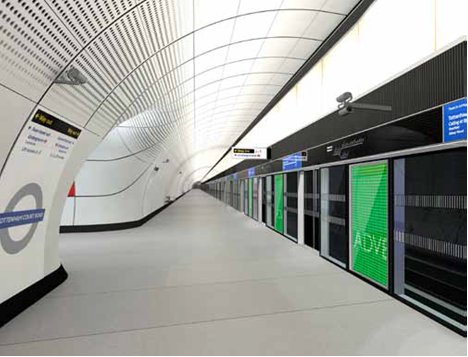
Figure 1 – Typical Platform
Photometry
1. Normal Illuminance Levels
Illuminance Level lighting has been designed in accordance with the LUL “Lighting of London Underground Assets” Document Number 1- 066 Issue No. A2, dated February 2008.
The standard requires consideration to be primarily given to task-based activities for passengers and staff in specific locations, table 1 provides the compliant values adopted across the Crossrail project.
Illuminance values (E) as described in table 1 are measured on the horizontal plane a second value (Uo) provides a uniformity figure. This is to ensure a consistent light distribution across the measured area. Specific tasks that require focal recognition, such as reading detail on passenger help points and the network maps are measured vertically.
Emergency lighting is a consistent vale of 15 lux across all areas in stations, shafts and portals uniformity is not applied to this figure. To verify that the lighting installation satisfies the design parameters, areas are measured in m² sections across all areas with a lux meter, the reading in each measured square must satisfy the requirements of the standard.
Table 1 – Lux Table
Task / Sub Area
Illuminance (E)
Uniformity (Uo)
Colour Rendering
Colour Temperature
Measurement Plane
Emergency illuminance (E)
Escalators
Stepping on and off
200
0.75
80+ 5000k Floor level 15 On Escalator (Ascending / Descending)
150
0.8 80+ 5000k Pitch line of escalator 15 Concourses
General illumination (Circulation) 150 0.4 80+ 3000k Floor level 15 Reading display information (vertical) 100 0.5 80+ 3000k Vertical plane N/A Cross Passage General illumination (Circulation) 150 0.4 80+ 5000k Floor level 15 Platforms General illumination (Circulation) 150 0.5 80+ 3000k Floor level 15 Help points, journey planner (vertical) 200 0.5 80+ 3000k Vertical plane N/A Reading display information (vertical) 100 0.5 80+ 3000k Vertical plane N/A Boarding / Alighting from trains 200 0.5 80+ Dynamic 3000k; 5000k Floor level 15 2. Colour Rendering
Colour rendering values aid and enhance the appearance of saturated colours (the band width of the light from the light source), this can affect the appearance of brightness on surface objects, the LUL standard requires a min glare index value of 65. Colour rendering index (Ra) A is measured, between 0 and 100, of the ability of a lamp to reproduce the colour of objects in comparison to their aspect under a natural or reference source of light. All lighting fixture used project wide have a minimum or higher value of 80 (RA) which will aid in improving the safety and visual experience of all in this new subsurface environment.
Lighting Control
The lighting control for all locations is a Digital Addressable Lighting Interface system (DALI).
The primary purpose for a lighting control system was the benefit it afforded for health status reporting, this provides detailed location information of any lighting component failures, to assist the maintainer in identifying replacement requirements efficiently.
The system provides individually addressable switching, dimming and monitoring of DALI luminaires. In the back of house areas, local control is provided via wall switches and multi sensors.
For those areas open to the public, central controls are programmed via the Lightscape Software; an interactive graphical tool displaying comprehensive, real-time information on the lighting and system operation.
Software
Energy efficiency is maximised by relating lighting closely to occupation, and reducing lighting levels as much as possible. The system incorporates manual switching, presence and absence detection within back of house areas. Lighting in areas exposed to natural light can be dimmed based upon reflected daylight.
The system combines the open protocol technologies of Lon and DALI for energy-efficient control of lighting. DALI digital control enables lighting levels to be finely controlled through dimming and energy savings to be subtly achieved. DALI also provides precise digital control as well as the benefits of lamp and ballast failure detection. The distributed intelligence system uses these networks to provide total flexibility of control; switching, dimming and monitoring of DALI luminaires.
The emergency monitoring feature of Lightscape provides the user with a documentation of emergency tests including times, duration and pass or fail status, including operational status of each emergency LED fitting. The Lightscape system also provides graphical feedback of the lighting installation including active status of each lamp. The software provides a ‘window’ into the lighting installation enabling the user to manage and monitor the system and display the active status of each luminaire against background station-specific graphic screens. The software also enables complete management & monitoring of the lighting installation and allows switching and dimming arrangements to be adapted through drag-and-drop binding.
The complete system operation, including sensor time-out periods and daylight-linking thresholds is configurable through the graphical software and may be adjusted to suit the operational and changing requirements of the client.
Emergency Lighting
Emergency escape and exit lighting is supplied from the emergency lighting UPS system which provides continuous illumination of the station during either partial mains failure (failure of either the A or B supply) or total mains failure. The UPS battery autonomy is 3 hours for emergency lighting in all areas project wide.
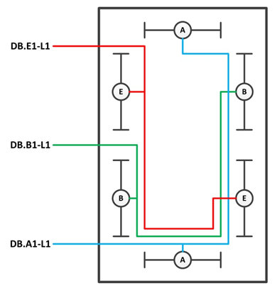
Figure 2 – Typical Emergency Lighting Room Arrangement (EM shown in Red)
The minimum arrangement of emergency lighting is every third fitting will have a UPS emergency supply, but the frequency of emergency fitting is dependant upon the lighting design delivering a minimum of 15 Lux across all areas. Emergency escape lighting has been designed to be resilient; this is achieved with the interleaving of emergency lighting circuit across recognised escape routes and circuit derived from different emergency distribution boards where feasible, all these factors assist in creating the safest subsurface environment possible
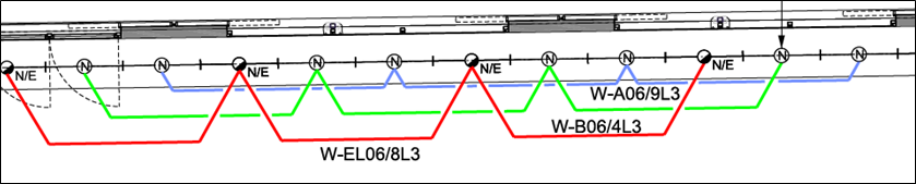 Figure 3 – Typical Platform Emergency Lighting Arrangement (EM shown in Red)
LED Specification
Luminaires generally consist of components that will be “easily” exchanged without removing the fitting body from its location, common components are the LED chips mounted and configured on a board, LED technology during the Crossrail project delivered 60/80 lm/w Lumens per watt output providing a lighting power ratio efficiency of 43.9% light output.
The DALI drivers mounted within the luminaires have a dimming capability range of 1-100%, and a Power factor vs load >0.95. The drivers also have the following protective features: over temperature, short-circuit, overload, reduced surge amplification, these are electronic control features to protect and prevent short term failures. The expected life-time of both the LED and the driver components is 60,000-100,000 hours.
LED lighting is a point light source which requires careful diffusion to manage glare reduction and produce a suitable beam angle for the application of the light source. LED modules need a consistent pitch (Spacing of the LEDs on the LED board) and also require an optimum distance between the module and the diffuser usually about 6cm as shown in Figure 4.
Homogenous diffusion of the LED light source is a result of the correct selection of Cellular Diffuser not all micro cellular diffuser are the same and have to be specified correctly, good diffusions should appear as shown in Figure 5.
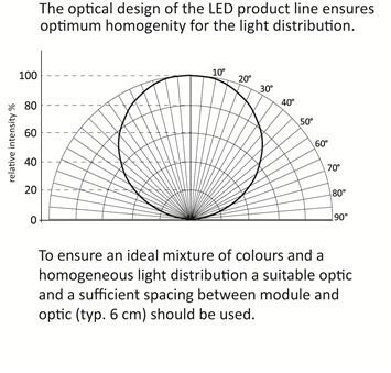
Figure 4 – Optimum Diffusion distance from the LED Module
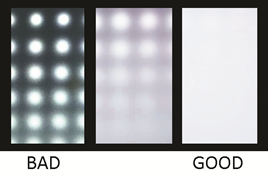
Figure 5 – Cellular Diffusion
LED Colour Temperature and Wayfinding
Colour temperature has been utilised to promote passenger wayfinding in public areas, “Intuitive wayfinding” has long been recognised in airports and large high volume public spaces to assist people in making intuitive decisions concerning direction of movement through large open spaces.
Cool White (5000-7000K) is used in areas that are considered as “transition spaces” – spaces where people are not encouraged to settle.
Warm White (3000-4000K) is applied to wayfinding areas and spaces that represent final destinations such as platforms.
Below in Figure 6 the cross passage and escalator sections are (fast movement) cool colour temperature showing areas of high volume pedestrian flow. The concourse and platform sections (slower movement) are warm colour temperature areas, intersections where passengers decide upon their choice of direction and arrive at the platform destination.
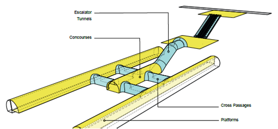
Figure 6 – Fast and Slow-Moving Areas
Generic Luminaire Types
1. Platform Edge Screen Light Box
The platform lighting is provided by a visually seamless band of light located directly above the platform screen doors, each unit is known as the PES (Platform Edge Screen) light box, the luminous section of the glass diffuser is 1100mm x 1500mm long. The luminaire is back lit with 3 no LED board arrays. Each board section consists of three boards fused together with a flexible hinge mechanism. The LED driver is mounted on the top board section, one driver controls each one of the board arrays, as detailed below in Figure 7. The luminaire was subjected to security testing and all materials had to meet the requirements of LUL 1-085 Issue A3 Fire Safety Performance of Materials.
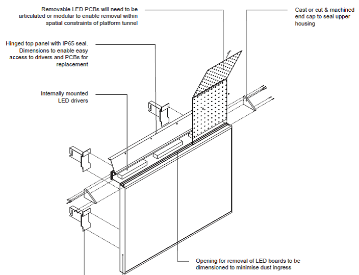
Figure 7 – PES Lightbox
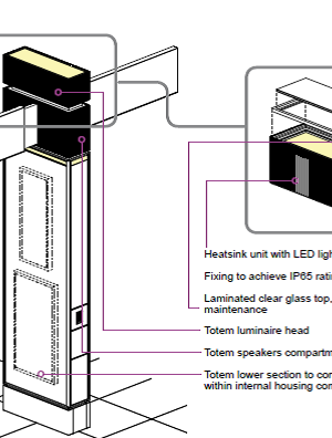
2. The Totem
The Totem is the primary source of lighting located in the station lower concourse; it combines wayfinding signage with the top section consisting of a high-powered LED uplighter, the totem also houses 6no; emergency lighting units located at various points both vertically and horizontally on the totem body.
The Totems are generally spaced at 9m intervals, illuminating a tunnel area of 8.1m in diameter. The luminaire provides up lighting onto the GRC wall and ceiling cladding material, and distributes a consistent lighting level onto the floor surface, providing horizontal and vertical illuminance of 150 lux and 0.5Uo (uniformity).
The top section of the luminaire is constructed from aluminium, and acts as a passive heat sink to control the ambient operating temperature of the LED units to (35°c) to maintain and prolong the LED life, it as acts as a distinctive architectural feature.
A glass laminated micro louvre is incorporated into totems located nearest to the base of escalators, to mitigate any direction glare that could be seen by passengers.
The totem was designed for the sub surface environment meeting the same requirements as the platform lights.
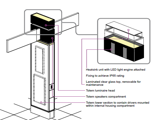
Figure 8 – Totem Sketch
3. The Recessed Escalator Deck Light
The escalator tunnel is illuminated by two independent lighting sources, a LED tape which provides a compliant lighting level on the escalator tread (150 Lux .08Uo) and a luminaire that is recessed into the escalator deck. The deck light provides the vertical illuminance and the perception of a guiding light that will focus passengers to concentrate on the direction of travel.
The luminaire is spaced at regular intervals of 1870mm centres along the length of the escalator central deck and is 1500mm long x 305mm wide. The LED light engine has an optical arrangement comprising of three layers of diffusion, which include a primary specular beam cover providing a homogenous uniform appearance, with a 70-degree beam angle. If viewed directly, the design is unique in providing a high level of light transmission output whilst glare is virtually eradicated.
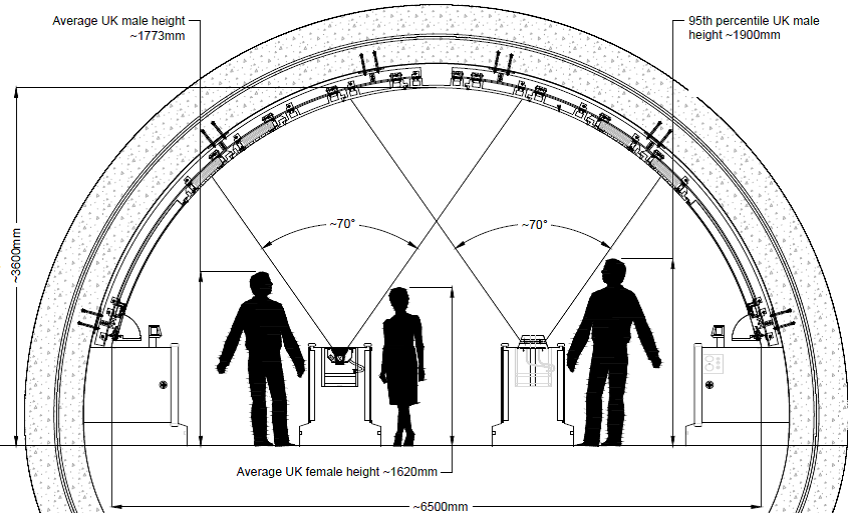
Figure 9 – Position and Beam direction of the Deck Light
4. Cross-Passage Lighting Service Boom
The cross-passage service boom is located in the lower concourse area of the station it illuminates the cross-passages between the platforms and the lower concourse passenger tunnels, providing 150 Lux 0.5 Uo and a colour temperature of 5000K (fast moving area) see Figure 10.
The design needed to satisfy and include a number of third party equipment interfaces, whilst maintaining the required frequency of luminaires to provide compliant lighting levels.
The Lighting Service Boom, which also contains the CMS, Dome Camera, Speakers and Multi-directional Antenna, needed to be easily accessible for access and maintenance of the third-party services.
Of major significance is the lit effect of the luminaire. The visual appearance of lit surface of the luminaire has to visually diffuse from all viewing angles with no visible colour shift or shadowing. It is to be noted, the Cross Passages are not uniform in length, nor straight in most station locations, requiring various custom designed luminaire units to allow for these different dimensions, curves and angles.
Overall, the luminaire was designed to provide a high efficiency with a wide angle, symmetrical distribution. This proved achievable using a high transmission micro cellular diffuser that evenly diffuses the LED sources and is sandwiched between the glass panels. The combination of a very fine surface texture and special diffusing, light-scattering additives result in a consistent and evenly lit luminaire.
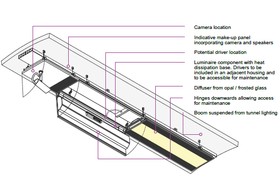
Figure 10 – Cross-Passage Service Boom Luminaire
Material Compliance
All lighting materials used on the CRL project are required to be evaluated for material content; the aim is to ensure that all product components have been considered to be ALARP in the use of combustible and toxicity constitution meeting the requirements of LUL 1-085 Issue A3 Fire Safety Performance of Materials. Products should also demonstrate that they are capable of meeting the required technical performance criteria, i.e. fit for purpose. CRL hold a register of material that have been submitted for evaluation and have been deemed suitable to be used in the proposed location.
This has been particularly challenging to the lighting industry as generally lighting diffusion materials are manufactured from polycarbonate plastics these have traditionally provided optimum diffusion quality and performance. Fire compliant glass products have been utilized to replace the polycarbonate material and significant investment and development has been required to develop glass material with minimal transmission loss.
Conclusion
The lighting design and installation line wide has been developed to incorporate a safe environment for the public, ensuring life safety systems have been developed in line with current legislation and providing maximum system resilience for safe evacuation. Navigation and wayfinding through the large public areas has been enhanced with the use of colour temperature and indirect illumination, whilst aiding to accentuate the many architectural features across the project.
Lighting products and systems have been designed with specific considerations given to provide minimal maintenance intervention and interruption to the efficient operation of the railway, whole life cost evaluation of luminaires in both public and back of house areas, will ensure future efficiency, The Elizabeth line will provide passengers with an unrivalled travel experience.
Referenced Standards
LUL 1-085 Fire safety performance of materials
LUL 1-066 Lighting of London Underground Assets
BS 5266 Pt.1:2011 Emergency Lighting. Code of practice for the emergency escape lighting of premises
Draft Baseline Report of the ICNIRP European Environment and Health Strategy (COM 2003)338 final) Directive (Sept 2012)
EN-60598 Luminaires Part 1. General requirements and tests
CRL1-XRL-Z-GPD-CR001-50004 Rev 3.0 Crossrail Material Compliance Record Procedure (MCR)
BS 6972 1988 Specification for general requirements for luminaires supporting couplers for domestic, light industrial and commercial use
BS 7001 1988 Specification for interchangeability and safety of a standardized luminaire supporting coupler
Crossrail Impact resistance / Explosion conformity.
BS EN 12464–1:2002 Lights and lighting. Lighting of work places. Indoor work places
IEC 62386 Digital addressable lighting interface – Part 209: Particular requirements for control gear.
BS EN 13032-1:2004+A1:2012 Light and lighting. Measurement and presentation of photometric data of lamps and luminaires. Measurement and file format.
C100 RIBA Stage F1 Constructability, Access & Maintenance Report, document reference C100-ATK-K2-TSY-CRG02-00001, revision 2.0
Crossrail report “Safe Maintenance of Systems in Proximity to Overhead Line Equipment (OHLE)”, document reference CRL1-PDP-Z-RGN-CRG02-50001 revision 1.0
Crossrail report “Area above PSD HAZID Report”, document reference: CRL1-PDP-Z7-RGN-CRG03-50002, version 1.0
Crossrail report “Review of Underground Station Platform Fire Safety”, document reference: CRL1-PDP-Z-RGN-CRG02-50002, revision 2.0
Crossrail report “Platform Cross Section Design Development Report”, document reference: CRL1-PDP-Z-RAE-CRG02-00002 V1.2
Crossrail report “Platform Edge Screen (PES) Systems Safety, Constructability, Functionality and Maintainability Report”, document reference: “CRL1-XRL-E-RGN—CR001_Z-6-50001, revision 1.0
C100-ATK-A-RGN-CRG02-50063 C100 Architectural Common Component Design: RIBA Stage F1- Lighting Design Guide
-
Authors
Paul Kerrigan BEng CEng MIET - Crossrail Ltd
Paul is Crossrail Lighting and UPS Engineer. He has worked on the project for 10 years with key responsibilities for developing lighting, UPS systems and LV Electrical Systems within all stations, shafts and portals throughout the project.
